CN111924552B - A multi-angle double-station bagged material stacking device - Google Patents
A multi-angle double-station bagged material stacking device Download PDFInfo
- Publication number
- CN111924552B CN111924552B CN202010658304.2A CN202010658304A CN111924552B CN 111924552 B CN111924552 B CN 111924552B CN 202010658304 A CN202010658304 A CN 202010658304A CN 111924552 B CN111924552 B CN 111924552B
- Authority
- CN
- China
- Prior art keywords
- frame
- conveying
- stacker
- stacker frame
- transposition
- Prior art date
- Legal status (The legal status is an assumption and is not a legal conclusion. Google has not performed a legal analysis and makes no representation as to the accuracy of the status listed.)
- Active
Links
- 239000000463 material Substances 0.000 title claims abstract description 91
- 230000007246 mechanism Effects 0.000 claims abstract description 174
- 230000017105 transposition Effects 0.000 claims abstract description 48
- 239000000725 suspension Substances 0.000 claims description 4
- 238000010586 diagram Methods 0.000 description 12
- 238000004519 manufacturing process Methods 0.000 description 6
- 238000000034 method Methods 0.000 description 6
- 238000013461 design Methods 0.000 description 3
- 238000012856 packing Methods 0.000 description 2
- 230000009286 beneficial effect Effects 0.000 description 1
- 238000004891 communication Methods 0.000 description 1
- 125000004122 cyclic group Chemical group 0.000 description 1
- 238000003032 molecular docking Methods 0.000 description 1
Images


Classifications
-
- B—PERFORMING OPERATIONS; TRANSPORTING
- B65—CONVEYING; PACKING; STORING; HANDLING THIN OR FILAMENTARY MATERIAL
- B65G—TRANSPORT OR STORAGE DEVICES, e.g. CONVEYORS FOR LOADING OR TIPPING, SHOP CONVEYOR SYSTEMS OR PNEUMATIC TUBE CONVEYORS
- B65G61/00—Use of pick-up or transfer devices or of manipulators for stacking or de-stacking articles not otherwise provided for
Landscapes
- Stacking Of Articles And Auxiliary Devices (AREA)
Abstract
本发明公开的一种多角度双工位的袋装物料码垛装置,包括码垛机框架、上料输送机构、拨片转位机构、推动机构和转向换位输送装置,所述上料输送机构安装在码垛机框架前端,拨片转位机构与上料输送机构后端配合,转向换位输送装置位于推动机构后端,推动机构与转向换位输送装置配合。上料输送机构与袋装物料流水线输出端连接,拨片转位机构将袋装物料依据生成的码垛方案将袋装物料推送到指定的推送机构,推送机构将袋装物料推送到转向换位输送装置中,转向换位输送装置依据码垛方案在车宽方向进行移动,将袋装物料码垛到车厢的指定位置。
The invention discloses a multi-angle double-station bagged material stacking device, comprising a stacker frame, a feeding conveying mechanism, a paddle indexing mechanism, a pushing mechanism and a steering indexing conveying device. The mechanism is installed at the front end of the stacker frame, the paddle indexing mechanism cooperates with the rear end of the feeding and conveying mechanism, the steering indexing conveying device is located at the rear end of the pushing mechanism, and the pushing mechanism cooperates with the steering indexing conveying device. The feeding conveying mechanism is connected to the output end of the bagged material assembly line. The paddle indexing mechanism pushes the bagged material to the designated pushing mechanism according to the generated palletizing plan, and the pushing mechanism pushes the bagged material to the steering indexing position. In the conveying device, the turning and transposition conveying device moves in the width direction of the vehicle according to the stacking plan, and stacks the bagged materials to the designated position of the carriage.
Description
技术领域technical field
本发明设计袋装物料码垛技术领域,具体地说是一种多角度双工位的袋装物料码垛装置。The invention is designed in the technical field of bagged material stacking, in particular to a bagged material stacking device with multi-angle and double stations.
背景技术Background technique
目前,袋装物料装车工作主要采用人工方式进行,工作环境比较恶劣,劳动强度较大,企业成本比较高。At present, the loading of bagged materials is mainly carried out manually, the working environment is relatively harsh, the labor intensity is relatively high, and the enterprise cost is relatively high.
现有的袋装物料码垛机构存在以下问题,1、袋装物料将在平台段输送机构带动下撞击到平台段输送机构顶端的挡板,造成袋装物料变形,袋装物料的平整度差,影响码垛质量;2、气缸推动的方式推动袋装物料换位,必须等待气缸收回空出工作空间才能进行下一包袋装物料操作,影响工作效率;3、码垛方向单一,只能单方向码垛,无法充分利用车厢空间。The existing bagged material palletizing mechanism has the following problems: 1. The bagged material will be driven by the platform section conveying mechanism to hit the baffle at the top of the platform section conveying mechanism, resulting in deformation of the bagged material and poor flatness of the bagged material , affecting the quality of the stacking; 2. The way of pushing the cylinder pushes the bagged materials to transposition, and you must wait for the cylinder to recover to vacate the working space before the next bagged material operation, which affects the work efficiency; 3. The stacking direction is single, only One-way palletizing cannot make full use of the compartment space.
发明内容SUMMARY OF THE INVENTION
本发明的目的在于解决上述问题,提供一种多角度双工位的袋装物料码垛装置,双皮带分段控制输送,防止袋装物料变形;实现了大质量袋装物料的可靠转位推送,工作过程中,不影响下一包袋装物料的操作,提高码垛整体效率;袋装物料码垛方向可控,可以进行多角度袋装物料码垛,充分利用车厢空间。The purpose of the present invention is to solve the above problems, and to provide a multi-angle double-station bagged material stacking device, the double belts control the conveying in sections, prevent the bagged material from being deformed, and realize the reliable indexing and pushing of the large-quality bagged material. , During the working process, it will not affect the operation of the next bag of bagged materials, and improve the overall efficiency of the stacking; the direction of the bagged material stacking is controllable, and the multi-angle bagged material stacking can be carried out, making full use of the compartment space.
本发明解决其技术问题所采取的技术方案是:The technical scheme adopted by the present invention to solve its technical problems is:
一种多角度双工位的袋装物料码垛装置,包括码垛机框架、上料输送机构、拨片转位机构、推动机构和转向换位输送装置,所述上料输送机构安装在码垛机框架前端,拨片转位机构安装在码垛机框架上端面前端,拨片转位机构与上料输送机构后端配合,推动机构对称的分布在码垛机框架两侧,转向换位输送装置与推动机构一一对应,转向换位输送装置位于推动机构后端,推动机构与转向换位输送装置配合。A multi-angle double-station bagged material stacking device includes a stacker frame, a feeding conveying mechanism, a paddle indexing mechanism, a pushing mechanism and a steering indexing conveying device. The front end of the stacker frame, the paddle indexing mechanism is installed at the front end of the upper end face of the stacker frame, the paddle indexing mechanism cooperates with the rear end of the feeding and conveying mechanism, and the pushing mechanism is symmetrically distributed on both sides of the stacker frame, and the steering is shifted. The conveying device is in one-to-one correspondence with the pushing mechanism, the steering transposition conveying device is located at the rear end of the pushing mechanism, and the pushing mechanism cooperates with the steering transposition conveying device.
进一步地,所述上料输送机构包括入料段输送结构、平台段输送机构和拉杆式调节机构,所述入料段输送结构后端与码垛机框架转动连接,平台段输送机构位于码垛机框架内,入料段输送结构后端与平台段输送机构前端配合,所述拉杆式调节机构前端与入料段输送结构连接,拉杆式调节机构后端与码垛机框架连接,所述码垛机框架上端位于入料段输送结构和平台段输送机构之间设有传感器。Further, the feeding conveying mechanism includes a feeding section conveying structure, a platform section conveying mechanism and a pull rod type adjusting mechanism, the rear end of the feeding section conveying structure is rotatably connected with the stacker frame, and the platform section conveying mechanism is located in the stacking machine. In the machine frame, the rear end of the conveying structure of the feeding section cooperates with the front end of the conveying mechanism of the platform section, the front end of the tie-rod adjustment mechanism is connected with the conveying structure of the feeding section, and the rear end of the tie-rod adjustment mechanism is connected with the frame of the palletizer. The upper end of the stacker frame is provided with a sensor between the conveying structure of the feeding section and the conveying mechanism of the platform section.
进一步地,所述入料段输送结构包括第一支撑框架和第一输送带,第一支撑框架上端两侧设有方管,第一输送带支撑在两所述方管之间,两所述方管之间之间设有驱动第一输送带传动的第一驱动辊和支撑第一输送带的第一拖辊,所述方管上端设有挡板;Further, the conveying structure of the feeding section includes a first support frame and a first conveyor belt, square pipes are arranged on both sides of the upper end of the first support frame, the first conveyor belt is supported between the two square pipes, and the two A first driving roller for driving the first conveyor belt and a first drag roller for supporting the first conveyor belt are arranged between the square tubes, and a baffle plate is arranged on the upper end of the square tube;
所述第一支撑框架后端设有第一螺栓,第一支撑框架通过第一螺栓与码垛机框架转动连接,第一支撑框架前端设有第二螺栓,所述第一支撑框架前端设有第三螺栓。The rear end of the first support frame is provided with a first bolt, the first support frame is rotatably connected with the stacker frame through the first bolt, the front end of the first support frame is provided with a second bolt, and the front end of the first support frame is provided with a second bolt. Third bolt.
进一步地,所述平台段输送机构包括第二支撑框架和第二输送带,第二支撑框架内设有驱动第二输送带传动的第二驱动辊和支撑第二输送带的第二拖辊;Further, the platform section conveying mechanism includes a second support frame and a second conveyor belt, and the second support frame is provided with a second drive roller for driving the second conveyor belt and a second drag roller for supporting the second conveyor belt;
所述拉杆式调节机构包括套筒和连接头,连接头对称分布在套筒两端,连接头与套筒之间螺纹连接,前端所述连接头与第二螺栓连接,后端所述连接头与码垛机框架上端连接,所述连接头上设有螺母。The pull rod type adjustment mechanism includes a sleeve and a connecting head, the connecting heads are symmetrically distributed at both ends of the sleeve, the connecting head and the sleeve are threadedly connected, the connecting head at the front end is connected with the second bolt, and the connecting head at the rear end is connected with the second bolt. It is connected with the upper end of the stacker frame, and the connecting head is provided with a nut.
进一步地,所述拨片转位机构包括刮板和第一皮带,码垛机框架两端均设有第一皮带轮,第一皮带两端与第一皮带轮配合,码垛机框架左端设有驱动第一皮带轮转动的驱动机构,刮板上端与码垛机框架之间滑动连接,第一皮带中间位置与刮板连接。Further, the paddle indexing mechanism includes a scraper and a first belt, both ends of the stacker frame are provided with first pulleys, both ends of the first belt are matched with the first pulley, and the left end of the stacker frame is provided with a drive. The driving mechanism for the rotation of the first pulley is slidingly connected between the upper end of the scraper and the stacker frame, and the middle position of the first belt is connected with the scraper.
进一步地,所述码垛机框架左端设有第一电机,第一电机输出轴与第一皮带轮连接;Further, the left end of the stacker frame is provided with a first motor, and the output shaft of the first motor is connected with the first pulley;
如图和图所示,所述刮板上端设有横板,横板前后两端设有导向轮,码垛机框架内设有圆导轨,导向轮与圆导轨配合,上段第一皮带与横板连接。As shown in the figure and the figure, the upper end of the scraper is provided with a horizontal plate, the front and rear ends of the horizontal plate are provided with guide wheels, the stacker frame is provided with a circular guide rail, the guide wheel is matched with the circular guide rail, and the first belt in the upper section is connected with the horizontal guide wheel. board connection.
进一步地,所述推动机构包括推板和第二皮带,码垛机框架前端以及中间位置均设有第二皮带轮,码垛机框架前端设有第二电机,第二电机输出轴与前端第二皮带轮连接,推板与码垛机框架之间滑动连接。Further, the pushing mechanism includes a push plate and a second belt, a second pulley is provided at the front end and the intermediate position of the stacker frame, a second motor is provided at the front end of the stacker frame, and the output shaft of the second motor is connected to the second pulley at the front end. The pulley is connected, and the sliding connection between the push plate and the palletizer frame.
进一步地,所述转向换位输送装置包括码垛机框架、悬挂式换位转位机构和盒式机械手机构,所述悬挂式换位转位机构安装在码垛机框架后端并与码垛机框架之间滑动连接,悬挂式换位转位机构左右对称的分布在码垛机框架内,盒式机械手机构安装在悬挂式换位转位机构下端。Further, the steering and transposition conveying device includes a stacker frame, a suspended transposition mechanism and a box-type manipulator mechanism. The machine frames are slidingly connected, and the suspended transposition and indexing mechanisms are symmetrically distributed in the stacker frame, and the box-type manipulator mechanism is installed at the lower end of the suspended transposition and indexing mechanism.
进一步地,所述悬挂式换位转位机构包括壳体和转轴,壳体与码垛机框架之间滑动连接,转轴与壳体之间转动连接,壳体内设有第三电机,所述第三电机输出轴上设有齿轮,转轴上端设有扇形齿轮,齿轮与扇形齿轮啮合,所述壳体通过电机皮带驱动。Further, the suspended transposition mechanism includes a casing and a rotating shaft, the casing and the palletizer frame are slidably connected, the rotating shaft and the casing are rotatably connected, a third motor is arranged in the casing, and the first The output shaft of the three motors is provided with a gear, the upper end of the rotating shaft is provided with a sector gear, the gear meshes with the sector gear, and the casing is driven by the motor belt.
进一步地, 所述盒式机械手机构包括箱体和开关门,转轴下端与箱体连接,开关门外侧一端与箱体内壁之间转动连接,箱体两侧均设有气缸,气缸活塞杆端设有连杆,气缸缸体端与箱体上端连接,连杆中间位置与箱体下端转动连接,气缸活塞杆端与连杆外侧一端转动连接,连杆内侧一端与开关门外侧连接。Further, the box-type manipulator mechanism includes a box body and an opening and closing door, the lower end of the rotating shaft is connected to the box body, the outer end of the opening and closing door is rotatably connected to the inner wall of the box, and both sides of the box body are provided with air cylinders, and the end of the cylinder piston rod is provided with a cylinder. There is a connecting rod, the cylinder end of the cylinder is connected with the upper end of the box, the middle position of the connecting rod is rotatably connected with the lower end of the box, the piston rod end of the cylinder is rotatably connected with the outer end of the connecting rod, and the inner end of the connecting rod is connected with the outer side of the opening and closing door.
本发明的有益效果是:The beneficial effects of the present invention are:
1、本发明包括码垛机框架、上料输送机构、拨片转位机构、推动机构和转向换位输送装置,所述上料输送机构安装在码垛机框架前端,拨片转位机构与上料输送机构后端配合,转向换位输送装置位于推动机构后端,推动机构与转向换位输送装置配合。上料输送机构与袋装物料流水线输出端连接,袋装物料从生产线通过上料输送机构进入到码垛机头中,拨片转位机构将袋装物料依据生成的码垛方案将袋装物料推送到指定的推送机构,推送机构将袋装物料推送到转向换位输送装置中,转向换位输送装置依据码垛方案在车宽方向进行移动,将袋装物料码垛到车厢的指定位置。袋装物料依次在车厢中进行码垛,码完一横排袋装物料,移动小车带动码垛框架后移进行下一排码放,直至码放完一层的最后一排,实现了袋装物料的自动码垛。1. The present invention includes a stacker frame, a feeding and conveying mechanism, a paddle indexing mechanism, a pushing mechanism and a turning and shifting conveying device. The feeding and conveying mechanism is installed at the front end of the stacker frame. The rear end of the feeding and conveying mechanism cooperates, and the steering transposition conveying device is located at the rear end of the pushing mechanism, and the pushing mechanism cooperates with the steering transposition conveying device. The feeding conveying mechanism is connected to the output end of the bagged material assembly line. The bagged material enters the stacker head from the production line through the feeding conveying mechanism, and the paddle indexing mechanism transfers the bagged material according to the generated stacking plan. It is pushed to the designated push mechanism, and the push mechanism pushes the bagged materials to the steering transposition conveying device. The steering transposition conveying device moves in the width direction of the vehicle according to the stacking plan, and stacks the bagged materials to the designated position of the carriage. The bagged materials are stacked in the carriage in turn. After stacking a horizontal row of bagged materials, the moving trolley drives the stacking frame to move backward for the next row of stacking, until the last row of the first floor is stacked, realizing the realization of bagged materials. Automatic palletizing.
2、本发明中上料输送机构包括入料段输送结构、平台段输送机构和拉杆式调节机构,入料段输送结构后端与平台段输送机构前端配合,码垛机框架上端位于入料段输送结构和平台段输送机构之间设有传感器,入料段输送结构与袋装物料生产流水线速度保持一致,并且一致转动,在传感器没有检测到袋装物料时,平台段输送机构保持静止,入料段输送结构转动;传感器检测到袋装物料时,平台段输送皮带转动,转动时间根据袋装物料长度与流水线速度设定。平台段输送机构转速持续降低,袋装物料将在平台段输送机构带动下逐渐减速,保证袋装物料不会撞击到平台段输送机构顶端的挡板,袋装物料形状不变,平整度好,保证码垛质量。2. In the present invention, the feeding conveying mechanism includes a feeding section conveying structure, a platform section conveying mechanism and a pull rod type adjustment mechanism. The rear end of the feeding section conveying structure cooperates with the front end of the platform section conveying mechanism, and the upper end of the stacker frame is located in the feeding section. There is a sensor between the conveying structure and the conveying mechanism of the platform section. The conveying structure of the feeding section keeps the same speed as that of the bagged material production line and rotates in unison. When the sensor does not detect the bagged material, the conveying mechanism of the platform section remains stationary, and the incoming The conveying structure of the material section rotates; when the sensor detects the bagged material, the conveying belt of the platform section rotates, and the rotation time is set according to the length of the bagged material and the speed of the assembly line. The speed of the conveying mechanism in the platform section continues to decrease, and the bagged materials will gradually decelerate under the drive of the conveying mechanism in the platform section, so as to ensure that the bagged materials will not hit the baffle at the top of the conveying mechanism in the platform section. Guarantee the quality of palletizing.
3、本发明中入料段输送结构后端与码垛机框架转动连接,入料段输送结构的倾斜角度可通过拉杆式调节机构进行调节,适应多种环境下的袋装物料生产线,实用性好。3. In the present invention, the rear end of the conveying structure of the feeding section is rotatably connected to the frame of the palletizer, and the inclination angle of the conveying structure of the feeding section can be adjusted by a lever-type adjusting mechanism, which is suitable for bagged material production lines in various environments, and is practical it is good.
4、本发明中拨片转位机构包括刮板和皮带,码垛机框架两端均设有皮带轮,皮带两端与皮带轮配合,码垛机框架左端设有驱动皮带轮转动的驱动机构,刮板上端与码垛机框架之间滑动连接,皮带中间位置与刮板连接,设定刮板初始位置位于码垛装置一侧,袋装物料进入到分包转位机构时,驱动机构带动皮带正向转动,皮带带动刮板移动,继而推动袋装物料分包到一侧;当下一包袋装物料进入到转位机构时,驱动机构电机反向转动,皮带带动刮板反向移动。充分利用码垛装置的上部空间,占用体积小;双滚轮的设计实现对大质量袋装物料的可靠转位推送;工作过程中,不影响下一包袋装物料的操作,提高码垛整体效率。4. In the present invention, the paddle indexing mechanism includes a scraper and a belt. Both ends of the stacker frame are provided with pulleys. Both ends of the belt are matched with the pulleys. The left end of the stacker frame is provided with a drive mechanism that drives the pulley to rotate. The scraper The upper end is slidingly connected with the frame of the palletizer, and the middle position of the belt is connected with the scraper. The initial position of the scraper is set to be on the side of the stacking device. When the bagged material enters the sub-packing indexing mechanism, the driving mechanism drives the belt forward. Rotation, the belt drives the scraper to move, and then pushes the bagged material to be subpackaged to one side; when the next bag of bagged material enters the indexing mechanism, the motor of the driving mechanism rotates in the reverse direction, and the belt drives the scraper to move in the reverse direction. Make full use of the upper space of the stacking device and occupy a small volume; the design of double rollers realizes reliable indexing and pushing of large-quality bagged materials; during the working process, it does not affect the operation of the next bag of materials, improving the overall efficiency of stacking .
5、本发明包括悬挂式换位转位机构和盒式机械手机构,所述悬挂式换位转位机构安装在码垛机框架后端并与码垛机框架之间滑动连接,盒式机械手机构安装在悬挂式换位转位机构下端。悬挂式转向换位输送装置初始位置位于码垛机头两侧,当袋装物料进入到盒式机械手之后,根据码垛指令中的角度信息,悬挂式换位转位机构驱动盒式机械手转动相应角度,袋装物料码垛方向可控,可以进行多角度袋装物料码垛,充分利用车厢空间。5. The present invention includes a suspended transposition and indexing mechanism and a box-type manipulator mechanism. The suspended transposition and indexing mechanism is installed at the rear end of the stacker frame and is slidably connected with the stacker frame. The box-type manipulator mechanism. It is installed at the lower end of the hanging transposition indexing mechanism. The initial position of the suspended steering and transposition conveying device is located on both sides of the palletizer head. When the bagged material enters the cassette manipulator, according to the angle information in the palletizing command, the suspended transposition and transposition mechanism drives the cassette manipulator to rotate accordingly. Angle, the stacking direction of bagged materials can be controlled, and multi-angle bagged materials can be stacked, making full use of the compartment space.
6、本发明中推动机构和悬挂式换位转位机构左右对称的分布在码垛机框架内,码垛框架实现袋装物料双通道输送,通过两套悬挂式转向换位输送装置配合实现装车码垛。6. In the present invention, the pushing mechanism and the suspended transposition and indexing mechanism are symmetrically distributed in the palletizer frame, and the stacking frame realizes double-channel conveyance of bagged materials. Car palletizing.
附图说明Description of drawings
为了更清楚地说明本发明实施例或现有技术中的技术方案,下面将对实施例或现有技术描述中所需要使用的附图作简单地介绍,显而易见地,对于本领域普通技术人员而言,在不付出创造性劳动的前提下,还可以根据这些附图获得其他的附图。In order to more clearly illustrate the embodiments of the present invention or the technical solutions in the prior art, the following briefly introduces the accompanying drawings that need to be used in the description of the embodiments or the prior art. In other words, other drawings can also be obtained based on these drawings without creative labor.
图1为本发明结构示意图;Fig. 1 is the structural representation of the present invention;
图2为本发明上料输送机构结构示意图;Fig. 2 is the structural schematic diagram of the feeding and conveying mechanism of the present invention;
图3为本发明入料段输送结构结构示意图一;FIG. 3 is a schematic structural diagram 1 of the conveying structure of the feeding section of the present invention;
图4为本发明入料段输送结构结构示意图二;Fig. 4 is a schematic diagram 2 of the conveying structure of the feeding section of the present invention;
图5为本发明平台段输送机构结构示意图;5 is a schematic structural diagram of the platform section conveying mechanism of the present invention;
图6为本发明拨片转位机构工作状态示意图;6 is a schematic diagram of the working state of the paddle indexing mechanism of the present invention;
图7为本发明刮板结构示意图一;7 is a schematic diagram of the structure of the scraper of the
图8为本发明刮板结构示意图二;Fig. 8 is the second schematic diagram of the scraper structure of the present invention;
图9为本发明转向换位输送装置工作状态示意图;9 is a schematic diagram of the working state of the steering transposition conveying device of the present invention;
图10为本发明悬挂式换位转位机构结构示意图一;FIG. 10 is a schematic structural diagram 1 of the hanging type transposition indexing mechanism of the present invention;
图11为本发明悬挂式换位转位机构结构示意图二;Fig. 11 is the second structural schematic diagram of the hanging transposition indexing mechanism of the present invention;
图12为本发明盒式机械手结构示意图一;Fig. 12 is the first structural schematic diagram of the cassette manipulator of the present invention;
图13为本发明盒式机械手结构示意图二。FIG. 13 is a second structural schematic diagram of the cassette manipulator of the present invention.
图中:码垛机框架1,传感器2,第一支撑框架3,第一输送带4,方管5,第一驱动辊6,第一拖辊7,第一螺栓8,第二螺栓9,第三螺栓10,第二支撑框架11,第二输送带12,第二驱动辊13,第二拖辊14,套筒15,连接头16,螺母17,挡板18,刮板18,皮带19,第一皮带轮20,第一电机20,横板22,导向轮23,圆导轨24,挡板25,推板26,第二皮带27,第二皮带轮28,第二电机29,壳体30,转轴31,第三电机32,齿轮33,扇形齿轮34,箱体35,开关门36,气缸37,连杆38。In the figure:
具体实施方式Detailed ways
为了使本技术领域的人员更好地理解本发明中的技术方案,下面将结合本发明实施例中的附图,对本发明实施例中的技术方案进行清楚、完整地描述,显然,所描述的实施例仅仅是本发明一部分实施例,而不是全部的实施例。基于本发明中的实施例,本领域普通技术人员在没有做出创造性劳动前提下所获得的所有其他实施例,都应当属于本发明保护的范围。In order to make those skilled in the art better understand the technical solutions of the present invention, the technical solutions in the embodiments of the present invention will be clearly and completely described below with reference to the accompanying drawings in the embodiments of the present invention. Obviously, the described The embodiments are only some of the embodiments of the present invention, but not all of the embodiments. Based on the embodiments of the present invention, all other embodiments obtained by persons of ordinary skill in the art without creative efforts shall fall within the protection scope of the present invention.
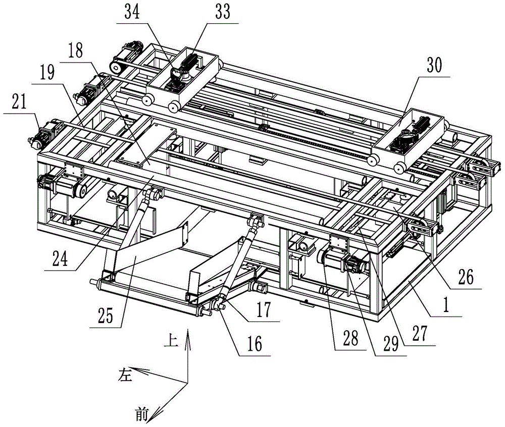
为方便描述,现定义坐标系如图1所示。For the convenience of description, the coordinate system is now defined as shown in Figure 1.
如图1所示,一种多角度双工位的袋装物料码垛装置,包括码垛机框架1、上料输送机构、拨片转位机构、推动机构和转向换位输送装置,所述上料输送机构安装在码垛机框架1前端,拨片转位机构安装在码垛机框架1上端面前端,拨片转位机构与上料输送机构后端配合,推动机构对称的分布在码垛机框架1两侧,转向换位输送装置与推动机构一一对应,转向换位输送装置位于推动机构后端,推动机构与转向换位输送装置配合。上料输送机构与袋装物料流水线输出端连接,袋装物料从生产线通过上料输送机构进入到码垛机头中,进入到码垛机头之后,拨片转位机构将袋装物料依据生成的码垛方案将袋装物料推送到指定的推送机构,既将上一袋装物料推送到右端的推送机构处,则将下一袋装物料推送到左端的推送机构处,推送机构将袋装物料推送到转向换位输送装置中,转向换位输送装置依据码垛方案在车宽方向进行移动,将袋装物料码垛到车厢的指定位置。袋装物料依次在车厢中进行码垛,码完一横排袋装物料,移动小车带动码垛框架后移进行下一排码放,直至码放完一层的最后一排,此时,提升架带动码垛框架上下移动,继续码放下一层袋装物料,实现了袋装物料的自动码垛。As shown in Figure 1, a multi-angle double-station bagged material stacking device includes a
如图2所示,所述上料输送机构包括入料段输送结构、平台段输送机构和拉杆式调节机构,所述入料段输送结构后端与码垛机框架1转动连接,平台段输送机构位于码垛机框架1内,入料段输送结构后端与平台段输送机构前端配合,所述拉杆式调节机构前端与入料段输送结构连接,拉杆式调节机构后端与码垛机框架1连接,所述码垛机框架1上端位于入料段输送结构和平台段输送机构之间设有传感器2。As shown in Figure 2, the feeding conveying mechanism includes a feeding section conveying structure, a platform section conveying mechanism and a pull rod type adjustment mechanism. The rear end of the feeding section conveying structure is rotatably connected to the
入料段输送结构与袋装物料生产流水线速度保持一致,并且一致转动,在传感器没有袋装物料时,平台段输送机构保持静止,入料段输送结构转动;传感器检测到袋装物料时,平台段输送皮带转动,转动时间根据袋装物料长度与流水线速度设定。平台段输送机构转速持续降低,袋装物料将在平台段输送机构带动下逐渐减速,保证袋装物料不会撞击到平台段输送机构顶端的挡板,袋装物料形状不变,平整度好,保证码垛质量。入料段输送结构的倾斜角度可通过拉杆式调节机构进行调节,适应多种环境下的袋装物料生产线,实用性好。The conveying structure of the feeding section keeps the same speed as the bagged material production line and rotates in unison. When there is no bagged material in the sensor, the conveying mechanism of the platform section remains stationary, and the conveying structure of the feeding section rotates; when the sensor detects the bagged material, the platform The conveyor belt rotates, and the rotation time is set according to the length of the bagged material and the speed of the assembly line. The speed of the conveying mechanism in the platform section continues to decrease, and the bagged materials will gradually decelerate under the drive of the conveying mechanism in the platform section, so as to ensure that the bagged materials will not hit the baffle at the top of the conveying mechanism in the platform section. Guarantee the quality of palletizing. The inclination angle of the conveying structure in the feeding section can be adjusted by the rod-type adjusting mechanism, which is suitable for bagged material production lines in various environments, and has good practicability.
如图2至图4所示,所述入料段输送结构包括第一支撑框架3和第一输送带4,第一支撑框架3上端两侧设有方管5,第一输送带4支撑在两所述方管5之间,两所述方管5之间之间设有驱动第一输送带4传动的第一第一驱动辊6和支撑第一输送带4的第一拖辊7,所述方管5上端设有挡板25,挡板25用于约束袋装物料的运动轨迹;As shown in FIGS. 2 to 4 , the conveying structure of the feeding section includes a
所述第一支撑框架3后端设有第一螺栓8,第一支撑框架3通过第一螺栓8与码垛机框架1转动连接,第一支撑框架3前端设有第二螺栓9,入料段输送机构底部通过第一螺栓8码垛机头底部固定在一起,上部第二螺栓9通过两套拉杆式调节结构与码垛机头上部连接在一起,所述第一支撑框架3前端设有第三螺栓10,第三螺栓10对接袋装物料流水线,与袋装物料流水线固定在一起。The rear end of the
如图2和图5所示,所述平台段输送机构包括第二支撑框架11和第二输送带12,第二支撑框架11内设有驱动第二输送带12传动的第二驱动辊13和支撑第二输送带12的第二拖辊14。As shown in FIG. 2 and FIG. 5 , the platform section conveying mechanism includes a
如图1和图2所示,所述拉杆式调节机构包括套筒15和连接头16,连接头16对称分布在套筒15两端,连接头16与套筒15之间螺纹连接,前端所述连接头16与第二螺栓9连接,后端所述连接头16与码垛机框架1上端连接,所述连接头16上设有螺母17,通过转动调节螺母,调节整个拉杆式调节机构长度,进而调整入料段段输送结构角度,方便与流水线对接。As shown in FIG. 1 and FIG. 2 , the pull rod type adjustment mechanism includes a
如图6所示,所述拨片转位机构包括刮板18和第一皮带19,码垛机框架1两端均设有第一皮带轮20,第一皮带19两端与第一皮带轮20配合,码垛机框架1左端设有驱动第一皮带轮20转动的驱动机构,刮板18上端与码垛机框架1之间滑动连接,第一皮带19中间位置与刮板18连接。所述码垛机框架1两端均设有支撑架,第一皮带轮20安装在支撑架内,支撑架5内设有涨紧机构,通过丝杠螺母驱动的方式张紧皮带。As shown in FIG. 6 , the paddle indexing mechanism includes a
设定刮板初始位置位于码垛装置一侧,袋装物料进入到分包转位机构时,驱动机构带动皮带正向转动,皮带带动刮板移动,继而推动袋装物料分包到一侧;当下一包袋装物料进入到转位机构时,驱动机构电机反向转动,皮带带动刮板反向移动。由于存在双滚轮设计,在推动质量较大的袋装物料过程中,导向机构动作不变形,能够平稳的将袋装物料运送到指定位置。在码垛过程中,整个转位机构随着袋装物料的输入,进行循环往复的运动,实现稳定可靠的袋装物料转位操作。充分利用码垛装置的上部空间,占用体积小;双滚轮的设计实现对大质量袋装物料的可靠转位推送;工作过程中,不影响下一包袋装物料的操作,提高码垛整体效率。Set the initial position of the scraper on the side of the stacking device. When the bagged material enters the sub-packing indexing mechanism, the driving mechanism drives the belt to rotate forward, and the belt drives the scraper to move, and then pushes the bagged material to be sub-packaged to one side; When the next bag of material enters the indexing mechanism, the motor of the driving mechanism rotates in the reverse direction, and the belt drives the scraper to move in the reverse direction. Due to the double-roller design, the guide mechanism does not deform during the process of pushing the bagged material with larger mass, and the bagged material can be transported to the designated position stably. During the stacking process, the entire indexing mechanism performs a cyclic reciprocating motion with the input of the bagged material to achieve stable and reliable indexing of the bagged material. Make full use of the upper space of the stacking device and occupy a small volume; the design of double rollers realizes reliable indexing and pushing of large-quality bagged materials; during the working process, it does not affect the operation of the next bag of bagged materials, improving the overall efficiency of stacking .
如图6所示,所述码垛机框架1左端设有第一电机21,第一电机21输出轴与第一皮带轮20连接;通过第一电机20驱动皮带轮转动,通过皮带19带动刮板左右移动。As shown in FIG. 6 , the left end of the
如图7和图8所示,所述刮板18上端设有横板22,横板22前后两端设有导向轮23,码垛机框架1内设有圆导轨9,导向轮23与圆导轨9配合,所述圆导轨9为圆柱形,导向轮23外圆柱面上设有凹槽,所述刮板18上端设有开口,第一皮带穿过开口,上段第一皮带19与横板22连接,导向轮23设有四个,横板22两侧各设有两个导向轮23。As shown in Fig. 7 and Fig. 8 , the upper end of the
如图1所示,所述推动机构包括推板26和第二皮带27,码垛机框架1前端以及中间位置均设有第二皮带轮28,码垛机框架1前端设有第二电机29,第二电机29输出轴与前端第二皮带轮28连接,推板26与码垛机框架1之间滑动连接,码垛机框架1内设有导轨,推板26两端设有导向轮,导向轮与导轨配合,第二电机29通过第二皮带27和第二皮带轮28驱动推板26前后移动。As shown in FIG. 1 , the pushing mechanism includes a
如图9所示,所述转向换位输送装置包括码垛机框架1、悬挂式换位转位机构和盒式机械手机构,所述悬挂式换位转位机构安装在码垛机框架1后端并与码垛机框架1之间滑动连接,悬挂式换位转位机构左右对称的分布在码垛机框架1内,盒式机械手机构安装在悬挂式换位转位机构下端。As shown in FIG. 9 , the steering and transposition conveying device includes a
为实现高速装车码垛,码垛框架实现袋装物料双通道输送,通过两套悬挂式转向换位输送装置配合实现装车码垛。悬挂式转向换位输送装置初始位置位于码垛机头两侧,当袋装物料进入到盒式机械手之后,根据码垛指令中的角度信息,悬挂式换位转位机构驱动盒式机械手转动相应角度,同时根据码垛指令中的位置信息,悬挂式换位转位机构带动盒式机械手在横向方向进行运动。当悬挂式换位转位机构到指定位置之后,盒式机械手两侧气缸打开,带动双开门门板打开,袋装物料完成码垛,盒式机械手关闭,同时悬挂式换位转位机构回到原位,等待进行该侧下一包袋装物料的码垛操作。In order to realize high-speed loading and palletizing, the palletizing frame realizes dual-channel transportation of bagged materials, and the loading and palletizing is realized through the cooperation of two sets of suspended steering and transposition conveying devices. The initial position of the suspended steering and transposition conveying device is located on both sides of the palletizer head. When the bagged material enters the cassette manipulator, according to the angle information in the palletizing command, the suspended transposition and transposition mechanism drives the cassette manipulator to rotate accordingly. At the same time, according to the position information in the stacking command, the hanging transposition indexing mechanism drives the cassette manipulator to move in the lateral direction. When the suspended transposition mechanism reaches the designated position, the cylinders on both sides of the cassette manipulator are opened, which drives the double-door door panels to open, the bagged materials are stacked, the cassette manipulator is closed, and the suspended transposition mechanism returns to the original position. position, waiting for the palletizing operation of the next bag of materials on this side.
如图10和图11所示,所述悬挂式换位转位机构包括壳体30和转轴31,壳体30与码垛机框架1之间滑动连接,所述壳体30两端设有导向轮,码垛机框架1内设有圆导轨,导向轮与圆导轨配合,转轴31与壳体30之间转动连接,壳体30内设有第三电机32,所述第三电机32输出轴上设有齿轮33,转轴31上端设有扇形齿轮34,齿轮33与扇形齿轮34啮合,第三电机通过齿轮和扇形齿轮驱动转轴转动。所述壳体30通过电机皮带驱动,包括电机和皮带,码垛机框架两端均设有皮带轮,皮带与皮带轮配合,电机固定在码垛机框架左端,电机输出轴与左端导向轮连接,电机通过皮带和导向轮驱动壳体左右移动。码垛机框架内设有圆导轨,导向轮与圆导轨配合,每个壳体上均设有八个导向轮,壳体下端四个角处各设有两个导向轮,分别位于壳体侧面的和壳体下端,实现壳体的限位。As shown in FIG. 10 and FIG. 11 , the suspended indexing mechanism includes a
如图12和图13所示,所述盒式机械手机构包括箱体35和开关门36,转轴31下端与箱体35连接,开关门36外侧一端与箱体35内壁之间转动连接,箱体35两侧均设有气缸37,气缸37活塞杆端设有连杆38,气缸37缸体端与箱体35上端连接,连杆38中间位置与箱体35下端转动连接,气缸37活塞杆端与连杆38外侧一端转动连接,连杆38内侧一端与开关门36外侧连接,通过气缸驱动开关门的启闭。As shown in FIG. 12 and FIG. 13 , the box-type manipulator mechanism includes a
在对本发明的描述中,需要说明的是,术语“左”、“右”、“上”、“下”等指示的方位或位置关系为基于附图所示的方位或位置关系,仅是为了便于描述本发明和简化描述,而不是指示或暗示所指的装置或元件必须具有特定的方位、以特定的方位构造和操作,因此不能理解为对本发明的限制。In the description of the present invention, it should be noted that the orientations or positional relationships indicated by the terms "left", "right", "upper", "lower", etc. are based on the orientations or positional relationships shown in the accompanying drawings, only for the purpose of It is convenient to describe the present invention and to simplify the description, rather than indicating or implying that the device or element referred to must have a particular orientation, be constructed and operate in a particular orientation, and therefore should not be construed as limiting the invention.
在本发明的描述中,需要说明的是,除非另有明确的规定和限定,术语“安装”、“相连”、“连接”应做广义理解,例如,可以是固定连接,也可以是可拆卸连接,或一体地连接 ;可以是机械连接,也可以是电连接,可以是直接相连,也可以通过中间媒介间接相连,可以是两个元件内部的连通。对于本领域的普通技术人员而言,可以具体情况理解上述术语在本发明中的具体含义。In the description of the present invention, it should be noted that the terms "installed", "connected" and "connected" should be understood in a broad sense, unless otherwise expressly specified and limited, for example, it may be a fixed connection or a detachable connection Connection, or integral connection; it can be a mechanical connection, an electrical connection, a direct connection, an indirect connection through an intermediate medium, or an internal communication between two elements. For those of ordinary skill in the art, the specific meanings of the above terms in the present invention can be understood in specific situations.
Claims (7)
Priority Applications (1)
| Application Number | Priority Date | Filing Date | Title |
|---|---|---|---|
| CN202010658304.2A CN111924552B (en) | 2020-07-09 | 2020-07-09 | A multi-angle double-station bagged material stacking device |
Applications Claiming Priority (1)
| Application Number | Priority Date | Filing Date | Title |
|---|---|---|---|
| CN202010658304.2A CN111924552B (en) | 2020-07-09 | 2020-07-09 | A multi-angle double-station bagged material stacking device |
Publications (2)
| Publication Number | Publication Date |
|---|---|
| CN111924552A CN111924552A (en) | 2020-11-13 |
| CN111924552B true CN111924552B (en) | 2022-07-05 |
Family
ID=73314134
Family Applications (1)
| Application Number | Title | Priority Date | Filing Date |
|---|---|---|---|
| CN202010658304.2A Active CN111924552B (en) | 2020-07-09 | 2020-07-09 | A multi-angle double-station bagged material stacking device |
Country Status (1)
| Country | Link |
|---|---|
| CN (1) | CN111924552B (en) |
Families Citing this family (3)
| Publication number | Priority date | Publication date | Assignee | Title |
|---|---|---|---|---|
| CN113501337A (en) * | 2021-07-29 | 2021-10-15 | 山东加法智能科技股份有限公司 | Stacking mechanical arm with stacking function and controllable rhythm |
| CN117104931A (en) * | 2023-05-15 | 2023-11-24 | 上海硅兴智能科技有限公司 | An intelligent loading device for cement, aggregate and other bagged materials |
| CN117509191B (en) * | 2023-11-24 | 2025-11-21 | 江苏尚辰机械有限公司 | Multifunctional flat tube collecting table |
Family Cites Families (5)
| Publication number | Priority date | Publication date | Assignee | Title |
|---|---|---|---|---|
| DE102014224550A1 (en) * | 2014-12-01 | 2016-06-02 | Krones Aktiengesellschaft | Apparatus and method for aligning grouped articles and / or piece goods |
| CN104960895B (en) * | 2015-06-08 | 2017-03-15 | 杭州娃哈哈集团有限公司 | Carton high speed arranging-in-row device |
| CN105836478B (en) * | 2016-05-30 | 2018-09-18 | 唐山智能电子有限公司 | Bagged material Automatic Code packs mechanism of car |
| CN106276323B (en) * | 2016-09-29 | 2018-07-31 | 重庆南商机器人科技有限公司 | A kind of bagged material automatic loading machine |
| CN210366003U (en) * | 2019-07-08 | 2020-04-21 | 绵阳蓝奥重型机械制造有限公司 | Package stopping and subpackaging assembly of loading robot |
-
2020
- 2020-07-09 CN CN202010658304.2A patent/CN111924552B/en active Active
Also Published As
| Publication number | Publication date |
|---|---|
| CN111924552A (en) | 2020-11-13 |
Similar Documents
| Publication | Publication Date | Title |
|---|---|---|
| CN111924552B (en) | A multi-angle double-station bagged material stacking device | |
| CN106429528A (en) | Automatic loading system capable of batch loading of packed materials | |
| CN111924553A (en) | An automatic palletizing device for bagged materials | |
| CN108163576B (en) | Folding conveying device on bagged material loading machine in factory building | |
| CN106425118A (en) | Special-shaped pipe feeding device | |
| CN111807020A (en) | An intelligent collection device for metal pipes | |
| CN115818125A (en) | Material conveying device with vertical rotary type and adjustable width | |
| CN103406277B (en) | Supporting-roller-type bidirectional switch | |
| CN111762585A (en) | An efficient and multifunctional fully automatic depalletizing, palletizing and loading machine | |
| CN114435910B (en) | Automatic collecting and arranging device for rubber sheets | |
| CN214879962U (en) | Fork mechanism for sorting system | |
| CN218057471U (en) | A miniature gantry palletizing device | |
| CN109809211B (en) | Loading platform | |
| CN215478540U (en) | Loading device | |
| CN118701695A (en) | Material conveying reversing platform and conveying device | |
| CN217732028U (en) | Bagged fertilizer bag folding robot | |
| CN111422639A (en) | A staggered unloading device between cargo boxes and its unloading method | |
| CN223673480U (en) | Connection conveyor | |
| CN209160848U (en) | An automatic connection device | |
| CN216944717U (en) | Lifting conveyor for conveying steel plates | |
| CN217625606U (en) | Integrative equipment of keeping in is carried to sheet material | |
| CN119218084B (en) | A transport pipe layout device for pipeline safety detection | |
| CN220115705U (en) | Telescopic line multi-station palletizing machine | |
| CN222098877U (en) | Device for caching carrier plate | |
| CN221853320U (en) | Mine is with dolly of unloading that has screening function |
Legal Events
| Date | Code | Title | Description |
|---|---|---|---|
| PB01 | Publication | ||
| PB01 | Publication | ||
| SE01 | Entry into force of request for substantive examination | ||
| SE01 | Entry into force of request for substantive examination | ||
| GR01 | Patent grant | ||
| GR01 | Patent grant |