CN111908169A - Powder metering type blanking device - Google Patents
Powder metering type blanking device Download PDFInfo
- Publication number
- CN111908169A CN111908169A CN202010924208.8A CN202010924208A CN111908169A CN 111908169 A CN111908169 A CN 111908169A CN 202010924208 A CN202010924208 A CN 202010924208A CN 111908169 A CN111908169 A CN 111908169A
- Authority
- CN
- China
- Prior art keywords
- pressure relief
- relief structure
- assembly
- blanking device
- stirring
- Prior art date
- Legal status (The legal status is an assumption and is not a legal conclusion. Google has not performed a legal analysis and makes no representation as to the accuracy of the status listed.)
- Granted
Links
Images


Classifications
-
- B—PERFORMING OPERATIONS; TRANSPORTING
- B65—CONVEYING; PACKING; STORING; HANDLING THIN OR FILAMENTARY MATERIAL
- B65G—TRANSPORT OR STORAGE DEVICES, e.g. CONVEYORS FOR LOADING OR TIPPING, SHOP CONVEYOR SYSTEMS OR PNEUMATIC TUBE CONVEYORS
- B65G65/00—Loading or unloading
- B65G65/30—Methods or devices for filling or emptying bunkers, hoppers, tanks, or like containers, of interest apart from their use in particular chemical or physical processes or their application in particular machines, e.g. not covered by a single other subclass
- B65G65/34—Emptying devices
- B65G65/40—Devices for emptying otherwise than from the top
-
- B—PERFORMING OPERATIONS; TRANSPORTING
- B65—CONVEYING; PACKING; STORING; HANDLING THIN OR FILAMENTARY MATERIAL
- B65G—TRANSPORT OR STORAGE DEVICES, e.g. CONVEYORS FOR LOADING OR TIPPING, SHOP CONVEYOR SYSTEMS OR PNEUMATIC TUBE CONVEYORS
- B65G65/00—Loading or unloading
- B65G65/005—Control arrangements
-
- B—PERFORMING OPERATIONS; TRANSPORTING
- B65—CONVEYING; PACKING; STORING; HANDLING THIN OR FILAMENTARY MATERIAL
- B65G—TRANSPORT OR STORAGE DEVICES, e.g. CONVEYORS FOR LOADING OR TIPPING, SHOP CONVEYOR SYSTEMS OR PNEUMATIC TUBE CONVEYORS
- B65G69/00—Auxiliary measures taken, or devices used, in connection with loading or unloading
Abstract
The invention provides a powder metering type blanking device, which comprises: the shell is provided with a blanking channel and comprises a main material section and a material storage section which are sequentially connected, and the bottom of the material storage section is provided with a discharge hole; the pressure relief assembly is arranged in the blanking channel and provided with a pressure relief channel, the pressure relief channel is communicated with the blanking channel, and materials enter the pressure relief channel from the blanking channel to be relieved and then are discharged from the discharge hole. Through the technical scheme that this application provided, can solve the problem that unloader among the prior art can't satisfy accuracy and cost requirement simultaneously.
Description
Technical Field
The invention relates to the technical field of blanking apparatuses, in particular to a powder metering type blanking device.
Background
At present, a blanking device is widely applied to the field of metering machinery as an important powder or granule conveying mechanism. The powder can be divided into good and the not good powder of mobility according to mobility, and among one of them unloader that powder that mobility is good was suitable for, the hob is vertical to be placed in defeated material passageway, and the hob sets up like this, mainly is for utilizing the dead weight of material for the unloading is more smooth. The conveying process of the existing blanking device is a conveying process for controlling the volume of materials. However, when the material is a pellet or a powder, the weight per unit volume changes due to many factors. This is because unfilled spaces exist between the particles of the granules or powders, and such spaces change depending on the state of the different granules or powders.
Therefore, in the prior art, the device for volume transmission has a large error in the final blanking weight result, and in order to overcome the above problems, a weight sensor is additionally arranged in the device, such as the device disclosed in the CN201420815123.6 patent, but this makes the structure of the whole equipment complicated, the manufacturing cost is greatly increased, the material particle size is different according to the material, and the required weight precision requirement is also different. This requires different precision weight sensors for different materials, which greatly increases the overall cost of the device.
Therefore, the existing blanking device cannot meet the requirements of blanking accuracy and cost at the same time.
Disclosure of Invention
The invention provides a powder metering type blanking device, which aims to solve the problem that the blanking device in the prior art cannot meet the requirements of accuracy and cost at the same time.
The invention provides a powder metering type blanking device, which comprises: the shell is provided with a blanking channel and comprises a main material section and a material storage section which are sequentially connected, and the bottom of the material storage section is provided with a discharge hole; the pressure relief assembly is arranged in the blanking channel and provided with a pressure relief channel, the pressure relief channel is communicated with the blanking channel, and materials enter the pressure relief channel from the blanking channel to be relieved and then are discharged from the discharge hole.
Furthermore, a pressure relief plane is arranged in the pressure relief channel, and the pressure of the material is relieved through the pressure relief plane.
Further, the pressure relief assembly comprises: the first pressure relief structure is annularly arranged on the inner wall of the blanking channel and provided with a first end and a second end which are arranged oppositely, the inner diameter of the first end of the first pressure relief structure is larger than that of the second end of the first pressure relief structure, and the first end of the first pressure relief structure is located at the upstream of the second end of the first pressure relief structure.
Further, the pressure relief assembly further comprises: the first pressure relief structure and the second pressure relief structure are arranged at an upper and lower interval, the projection of the first pressure relief structure and the projection of the second pressure relief structure on the horizontal plane are partially overlapped, the axis of the second pressure relief structure is overlapped with the axis of the blanking channel, the outer wall of the second pressure relief structure is spaced from the inner wall of the blanking channel, the second pressure relief structure is provided with a first end and a second end which are oppositely arranged, the outer diameter of the first end of the second pressure relief structure is smaller than that of the second end of the second pressure relief structure, and the first end of the second pressure relief structure is located at the upstream of the second end of the second pressure relief structure.
Further, the first pressure relief structure may have an inner diameter that decreases from the first end to the second end of the first pressure relief structure, and/or the second pressure relief structure may have an outer diameter that increases from the first end to the second end of the second pressure relief structure.
Furthermore, the inner wall of the first pressure relief structure is a first inclined plane, and the included angle between the first inclined plane and the horizontal plane is 30-50 degrees; the outer wall of the second pressure relief structure is a second inclined surface, and the included angle between the second inclined surface and the horizontal plane is 20-30 degrees.
Further, the first pressure relief structure is located above the second pressure relief structure, and the pressure relief assembly further comprises: the partition plate is arranged above the first pressure relief structure, the longitudinal section of the partition plate is of a conical structure, and the horizontal center line of the partition plate coincides with the horizontal center line of the blanking channel.
Further, powder measurement formula unloader still includes: stirring subassembly, stirring subassembly include the push rod, and the push rod rotationally sets up in the unloading passageway.
Further, the stirring subassembly still includes: the stirring shell is arranged in the feeding channel, one end of the pushing rod is positioned in the stirring shell, and the other end of the pushing rod extends to the discharging opening; the driving part is in driving connection with the pushing rod and is used for driving the pushing rod to rotate.
Further, the drive division sets up in the outside of casing, and the stirring subassembly still includes: the transmission assembly, transmission assembly's one end and drive division are connected, and transmission assembly's the other end is connected with the propelling movement pole, and drive division passes through transmission assembly drive propelling movement pole and rotates.
Further, the shell further comprises a transition connecting section, the transition connecting section is located between the main material section and the material storage section, the stirring assembly is at least partially located in the transition connecting section, and the pressure relief assembly is arranged between the transition connecting section and the material storage section.
Furthermore, two discharge ports are arranged on the shell side by side, the powder metering type blanking device comprises two stirring assemblies, and the two discharge ports and the two stirring assemblies are arranged in a one-to-one correspondence mode.
Further, powder measurement formula unloader still includes: the discharging device comprises a discharging hole, a discharging spiral and a pushing rod, wherein the discharging hole is formed in the end portion of the pushing rod, a discharging groove is formed in the side wall of the discharging spiral, and the discharging groove is spirally formed in the axial direction of the discharging spiral.
Further, powder measurement formula unloader still includes: and the injection structure is arranged at the discharge port and used for discharging the materials quantitatively.
Further, the pouring structure comprises: the quantitative piece is rotatably arranged below the shell and is provided with a plurality of quantitative holes at intervals along the circumferential direction, the quantitative holes are arranged corresponding to the discharge port, and each quantitative hole is provided with a discharging position and a disconnecting position which are rotated to the discharge port; the injection piece is fixed relative to the shell and located below the quantifying piece, the injection piece is provided with an injection port, the axis of the injection port is located on the projection of a circular line formed by the centers of the quantifying holes, and the axis of the injection port is not coincident with the axis of the discharge port.
Further, the stirring assembly further comprises a stirring rod, the stirring rod is connected with the pushing rod, and the stirring rod is used for stirring materials in the blanking channel.
By applying the technical scheme of the invention, the powder metering type blanking device comprises a shell and a pressure relief assembly, wherein the shell is provided with a blanking channel, the tail end of the blanking channel is provided with a discharge hole, and the pressure relief assembly is arranged in the blanking channel, so that the pressure relief assembly is utilized to relieve and buffer the material before the material falls to the discharge hole, the impact of the material above the material on the discharge hole when the material falls is reduced, the stability of the density of the material at the discharge hole can be kept, and the weight of the subsequent material blanking can be further ensured under the condition of constant delivery volume. The device simple structure, and be applicable to the material that mobility is good, it is with low costs, can satisfy the requirement of unloading accuracy and cost simultaneously.
Drawings
The accompanying drawings, which are incorporated in and constitute a part of this application, illustrate embodiments of the invention and, together with the description, serve to explain the invention and not to limit the invention. In the drawings:
FIG. 1 is a sectional view of a powder metering type blanking device according to an embodiment of the present invention;
FIG. 2 is a cross-sectional view of another perspective of a powder metering feeder according to an embodiment of the present invention;
FIG. 3 is a cross-sectional view of another perspective of a powder metering feeder according to an embodiment of the present invention;
FIG. 4 is a sectional view of a powder measuring-type blanking device according to a second embodiment of the present invention;
FIG. 5 is a sectional view of another view of a powder measuring and feeding device according to the second embodiment of the present invention;
FIG. 6 is a top view of a powder measuring and feeding device according to a second embodiment of the present invention;
FIG. 7 is an exploded view of a powder metering type blanking device according to a third embodiment of the present invention;
FIG. 8 is a side view of a powder measuring type blanking device according to a third embodiment of the invention;
fig. 9 is a statistical chart showing the number of times of blanking and the blanking amount of the conventional blanking device;
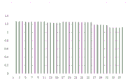
fig. 10 is a statistical chart showing the number of times of blanking and the blanking amount of the powder metering type blanking device provided by the embodiment of the invention.
Wherein the figures include the following reference numerals:
10. a housing; 10a, a discharge hole; 11. a main material section; 12. a transition connection section; 13. a storage section; 10b, the inner wall of the blanking channel;
20. a pressure relief assembly; 21. a first pressure relief structure; 211. a first end of a first pressure relief structure; 212. a second end of the first pressure relief structure; 21a, an inner wall of the first pressure relief structure; 22. a second pressure relief structure; 221. a first end of a second pressure relief structure; 222. a second end of the second pressure relief structure; 22a, an outer wall of the second pressure relief structure; 23. a partition plate;
30. a stirring assembly; 31. a push rod; 31a, a stirring rod; 32. stirring the shell; 33. a drive section; 34. a transmission assembly; 35. feeding spirally;
41. a dosing member; 411. a dosing aperture; 42. injecting the part; 421. and a pouring outlet.
Detailed Description
The technical solutions in the embodiments of the present invention will be clearly and completely described below with reference to the drawings in the embodiments of the present invention, and it is obvious that the described embodiments are only a part of the embodiments of the present invention, and not all of the embodiments. The following description of at least one exemplary embodiment is merely illustrative in nature and is in no way intended to limit the invention, its application, or uses. All other embodiments, which can be derived by a person skilled in the art from the embodiments given herein without making any creative effort, shall fall within the protection scope of the present invention.
As shown in fig. 1 to 3, an embodiment of the present application provides a powder metering type blanking device, including: a housing 10 and a pressure relief assembly 20. Wherein, casing 10 includes main material section 11 and the storage section 13 of connecting in order, and the bottom of storage section 13 has discharge gate 10 a. The housing 10 has a discharge passage, and specifically, the discharge passage is disposed through the housing 10, and the material is discharged from the discharge port 10a after falling down from the discharge passage. The pressure relief assembly 20 is arranged in the blanking channel, the pressure relief assembly 20 having a pressure relief channel, the pressure relief channel being in communication with the blanking channel. Specifically, in this embodiment, the pressure relief channel extends through the pressure relief assembly 20, the upper end of the pressure relief channel communicates with the upper blanking channel, and the lower end of the pressure relief channel communicates with the lower blanking channel. The material enters the pressure relief channel from the blanking channel to be relieved and then falls to the discharge hole 10 a. The pressure relief assembly 20 may be mechanically configured to cushion, relieve pressure, or cushion with some drive mechanism.
Through set up release subassembly 20 in the unloading passageway, can utilize release subassembly 20 to carry out release, buffering to the material like this before the material falls to discharge gate 10a, reduce the impact of top material to discharge gate 10a department material when the whereabouts, make the material can keep the stability of density in discharge gate 10a department, under the circumstances that the volume of sending out is invariable, and then can guarantee the weight of follow-up material unloading. The device has simple structure and is suitable for materials in various forms. This application compares with current device, need not set up the weighing device and weigh, also need not to use the position test device or the volume measurement device of control material memory space in the feed bin, its greatly reduced the manufacturing cost of device, the requirement of unloading accuracy and cost can be satisfied simultaneously to the device that this application provided.
Specifically, in this application, set up the pressure relief plane in this release passageway, carry out the release to the material through the pressure relief plane. The pressure relief plane can be a horizontal plane, can be limited to an inclined plane, can also be a curved surface or other structures, and only needs to slow down the falling impact force of the materials. In this application, the release plane is the inclined plane, carries out the release to the material through the inclined plane, and its simple structure is with low costs, and is effectual.
Wherein the pressure relief assembly 20 includes a first pressure relief structure 21, the first pressure relief structure 21 being annularly disposed on an interior wall of the blanking channel, the first pressure relief structure 21 having oppositely disposed first and second ends, an inner diameter of the first end 211 of the first pressure relief structure being greater than an inner diameter of the second end 212 of the first pressure relief structure, and the first end 211 of the first pressure relief structure being located upstream of the second end 212 of the first pressure relief structure. With the above structure, when the material falls, the material slides from the inner wall of the first end to the inner wall of the second end after falling on the first pressure relief structure 21, and then continuously falls from the second end. This allows the first pressure relief structure 21 to be used to cushion the material.
The pressure relief assembly 20 further comprises a second pressure relief structure 22, the first pressure relief structure 21 and the second pressure relief structure 22 are arranged at an interval from top to bottom, and the pressure relief capacity of the pressure relief assembly 20 can be further improved by arranging the second pressure relief structure 22, so that the impact of falling materials is further relieved.
In particular, the projections of the first pressure relief structure 21 and the second pressure relief structure 22 in the horizontal plane partially coincide, so that it is avoided that material, after falling through the first pressure relief structure 21, cannot fall onto the second pressure relief structure 22, and by means of the above-mentioned structure, the material must be relieved by passing through the first pressure relief structure 21 and the second pressure relief structure 22 in sequence when falling. The axis of the second pressure relief structure 22 coincides with the axis of the blanking channel, and the outer wall 22a of the second pressure relief structure is spaced from the inner wall 10b of the blanking channel, so that the material falls to the discharge hole 10a after being relieved by the second pressure relief structure 22. The second pressure relief structure 22 has oppositely disposed first and second ends, the first end 221 of the second pressure relief structure having an outer diameter less than an outer diameter of the second end 222 of the second pressure relief structure, and the first end 221 of the second pressure relief structure being located upstream of the second end 222 of the second pressure relief structure.
The pressure relief surfaces of the first pressure relief structure 21 and the second pressure relief structure 22 may be curved or wavy, or may have other structures. In this embodiment, the first pressure relief structure 21 has an inner diameter that gradually decreases from the first end to the second end of the first pressure relief structure 21, and the second pressure relief structure 22 has an outer diameter that gradually increases from the first end to the second end of the second pressure relief structure 22. This enables a gentle fall of material over the first and second pressure relief structures 21, 22.
Specifically, the inner wall 21a of the first pressure relief structure is a first inclined surface, and an included angle between the first inclined surface and a horizontal plane is 30 ° to 50 °. The outer wall 22a of the second pressure relief structure is a second inclined surface, and the included angle between the second inclined surface and the horizontal plane is 20-30 degrees. Through the structure, the material can be buffered, and the phenomenon that the material blanking time is not too long can be avoided, so that the discharging speed is influenced. In this embodiment, the angle between the first inclined plane and the horizontal plane is 45 °, and the angle between the second inclined plane and the horizontal plane is 25 °.
Wherein, the first pressure relief structure 21 may be a separate component or may be integrally formed with the housing 10; the second pressure relief structure 22 may be a separate component or may be integrally formed with the housing 10. In this embodiment, the first and second pressure relief structures 21, 22 are each separate components, which facilitates manufacture, installation, and maintenance of the components.
The first pressure relief structure 21 may be disposed above the second pressure relief structure 22 or below the second pressure relief structure 22, with the first pressure relief structure 21 being located above the second pressure relief structure 22 in this embodiment. The pressure relief assembly 20 further comprises a partition plate 23, the partition plate 23 is arranged above the first pressure relief structure 21, the longitudinal section of the partition plate 23 is of a conical structure, and the horizontal center line of the partition plate 23 coincides with the horizontal center line of the blanking channel. Because the first pressure relief structure 21 is an annular structure, the material can directly fall from the hollow part in the middle of the first pressure relief structure 21 with a certain probability when falling, so that the first pressure relief structure 21 loses certain pressure relief effect and function, and the possibility that the material directly falls from the hollow part of the first pressure relief structure 21 can be reduced as much as possible and the pressure relief effect can be increased by arranging the partition plate 23 above the first pressure relief structure 21 and enabling the horizontal center line of the partition plate 23 to coincide with the horizontal center line of the blanking channel. The material in the middle can fall onto the first pressure relief structure 21 along the inclined planes at the two sides of the partition plate 23 by utilizing the partition plate 23, and can slide towards the two sides uniformly, the material can flow into the channel below the channel in an equally divided way, so that the flow of the powder in the blanking channel is uniform, the consistency is good, the subsequent pressure falling to the discharge port 10a is stable, and the precision of discharging can be further ensured.
The stirring assembly 30 may be provided in the apparatus of the present application, or the stirring assembly 30 may not be provided. In the case that the stirring assembly 30 is not provided, the material can fall to the discharge port 10a through the blanking channel and the pressure relief channel, and is discharged from the discharge port 10 a. If the stirring assembly 30 is provided, when the material is at the discharge port 10a, the stirring assembly 30 can be used to drive the material to be discharged from the discharge port 10 a. In this embodiment, the apparatus is provided with a stirring assembly 30, the stirring assembly 30 comprising a push rod 31, the push rod 31 being rotatably arranged in the blanking channel. The material can be driven out of the discharge hole 10a by the push rod 31. Specifically, a discharging spiral 35 can be arranged at the end of the pushing rod 31, a discharging groove is formed in the side wall of the discharging spiral, and the discharging groove is spirally formed in the axial direction of the discharging spiral 35, so that materials in the discharging groove can be pushed out from the discharging hole 10a in the rotating process of the pushing rod 31. And then can further control the unloading volume of commodity circulation through turned angle, conveniently control the unloading volume.
Wherein, still be provided with puddler 31a in order to stir the material in this stirring subassembly 30, puddler 31a is connected with push rod 31, can make puddler 31a and push rod 31 synchronous rotation to stir the material in the storage section 13 through puddler 31a, avoid the unusual production of material to make somebody a mere figurehead the not smooth phenomenon of whereabouts.
Specifically, the stirring assembly 30 further includes: an agitator housing 32 and a drive 33. The stirring shell 32 is arranged in the blanking channel, one end of the pushing rod 31 is positioned in the stirring shell 32, and the other end of the pushing rod 31 extends to the discharge hole 10 a. The driving part 33 is in driving connection with the pushing rod 31, and the driving part 33 is used for driving the pushing rod 31 to rotate. Through the structure, the materials can be prevented from falling into the stirring assembly 30, the stirring shell 32 can be used for isolating the internal parts from the materials, and the normal operation of the internal structure is ensured.
In the present embodiment, the partition plate 23 is disposed at the top of the agitator housing 32, so that the material is prevented from being accumulated on the top of the agitator housing 32.
The driving part 33 may be fixed to the housing 10 by a bracket, the driving part 33 is a driving motor, and the driving part 33 may be configured as a stepping motor in order to further control the discharging amount.
The driving portion 33 is disposed outside the housing 10, the stirring assembly 30 further includes a transmission assembly 34, one end of the transmission assembly 34 is connected to the driving portion 33, the other end of the transmission assembly 34 is connected to the pushing rod 31, and the driving portion 33 drives the pushing rod 31 to rotate through the transmission assembly 34. Specifically, the transmission assembly 34 may be configured as a synchronous belt, transmission teeth are disposed on the driving end of the driving portion 33 and the pushing rod 31, and the driving portion 33 and the pushing rod 31 are driven by the synchronous belt.
With drive division 33 setting in the outside of casing 10, can make the heat directly dispel the casing 10 outside, material, stirring assembly's some spare parts can not receive drive division 33 to generate heat and take place the inflation, like this can further improvement the stability of the ejection of compact, improved the precision of the ejection of compact.
Specifically, the housing 10 includes a main material section 11, a transitional coupling section 12, and a storage section 13 connected in sequence, the stirring assembly 30 is at least partially located in the transitional coupling section 12, and the pressure relief assembly 20 is disposed between the transitional coupling section 12 and the storage section 13. The main material section 11, the transition connection section 12 and the storage section 13 may be an integral structure or a separate structure. In this embodiment, the main material section 11, the transition connecting section 12 and the storage section 13 are separate bodies and can be connected to each other by fasteners, so as to facilitate the arrangement of the pressure relief assembly 20 and the stirring assembly 30 in the housing 10.
Specifically, the cross section of the main material section 11 can be cylindrical or elliptic cylindrical, so that the material can be evenly discharged, and the manufacturing cost is low. The sealing gaskets are arranged at the joints among the main material section 11, the transition connecting section 12 and the storage section 13, so that the sealing effect can be improved.
In the present embodiment, the first pressure relief structure 21 is enclosed at the periphery of the stirring housing 32, the second pressure relief structure 22 is arranged at the bottom of the stirring housing 32, and the pushing rod 31 penetrates out of the middle of the second pressure relief structure 22 and extends to the discharge hole 10 a. The pressure relief passages are formed between the first pressure relief structure 21 and the agitator housing 32 and between the second pressure relief structure 22 and the inner wall of the housing 10. The material storage section 13 is of a conical structure, can play a certain buffering role when the material falls down, and can guide the material to fall to the discharge hole 10 a.
For powder with good fluidity, the invention meets the requirement of improving precision and avoids the research and development of devices with high manufacturing cost. The flowability of the powder and pellet in the present invention was evaluated by: the powder and the granule are placed on the inner wall 21a of the first pressure relief structure or the outer wall 22a of the second pressure relief structure, and if the powder and the granule cannot slide off the inclined surface, the powder and the granule are considered to be materials with poor flowability, and the powder and the granule are also suitable for the invention.
As shown in fig. 4 to fig. 6, a second embodiment of the present application provides a powder metering type discharging device, which is different from the first embodiment in that two discharging ports 10a are arranged side by side on a housing 10, the powder metering type discharging device includes two stirring assemblies 30, and the two discharging ports 10a and the two stirring assemblies 30 are arranged in a one-to-one correspondence manner. Can improve ejection of compact speed like this, it is concrete, can set the helicla flute on the push rod to different pitches, through carrying out the unloading with different push rods, can satisfy the requirement of quick unloading and accurate unloading simultaneously.
As shown in fig. 7 and 8, a third embodiment of the present application provides a powder metering type blanking device, which is different from the first embodiment in that the powder metering type blanking device further includes: and the injection structure is arranged at the discharge port 10a, and the quantitative discharge of the materials can be controlled by arranging the injection structure.
Specifically, the pouring structure includes: a dosing member 41 and an ejection member 42. Wherein, ration piece 41 rotationally sets up in casing 10 below, and ration piece 41 is provided with a plurality of ration holes 411 along the circumferencial direction interval, and a plurality of ration holes 411 set up with discharge gate 10a corresponds, and every ration hole 411 has the unloading position and the disconnection position of rotating to discharge gate 10a department. The injection member 42 is fixed relative to the housing 10 and located below the quantitative member 41, the injection member 42 has an injection port 421, an axis of the injection port 421 is located on a projection of a circular line formed by centers of the quantitative holes 411, and an axis of the injection port 421 is not coincident with an axis of the discharge port 10 a. When the quantitative device 41 rotates to a position where one of the quantitative holes 411 is aligned with the discharge port 10a, the quantitative device is used as a blanking position, and a storage cavity formed by matching the space of the quantitative hole 411 and the injection member 42 stores a certain volume of materials, and when the quantitative device 41 continues to rotate to align the quantitative hole 411 with the injection port 421, the materials in the quantitative hole 411 can be discharged from the injection port 421, so that the purpose of quantitative blanking is achieved. The device simple structure, the unloading control is accurate.
In order to facilitate understanding of the device of the present application, a blanking experiment is performed by using the existing blanking device and the blanking device of the present application, and experimental data are shown in fig. 9 and 10, where fig. 9 is discharging data of the existing blanking device, and fig. 10 is discharging data of the blanking device of the present application.
The experimental contents are as follows: a certain amount of material is poured out each time from the time when the shell is filled with the material until the material in the shell is used up. In the figure, the abscissa is the blanking frequency for discharging the materials in the whole shell, and the ordinate is the blanking amount. As can be seen from fig. 9, in the discharging process, the material in the housing is less and less used along with the multiple times of discharging of the pushing rod, and the discharging amount is also reduced along with the reduction of the material amount in the housing. And as can be seen from fig. 10, the fluctuation range of the blanking amount thereof is significantly smaller than that in fig. 9. Therefore, the blanking device has the advantages of being good in discharging stability and high in precision.
For better understanding this application, this application unloader's use as follows:
the materials are stored in the main material section 11, when the materials fall by means of self weight, the partition plate 23 distributes the materials to two sides of the partition plate 23, the materials fall onto the first pressure relief structure 21, after pressure relief is carried out by the pressure relief plane of the first pressure relief structure 21, the materials slide onto the second pressure relief structure 22 for pressure relief again, and finally the materials fall to the bottom of the material storage section 13. The pressure of most materials is borne by the pressure relief assembly 20 in the whole blanking process, the pressure at the bottom of the material storage section 13 is mainly the gravity of the materials, so that the discharging pressure at the discharging port 10a can be kept at a constant pressure value, large fluctuation along with the change of the volume of the materials is avoided, and the flow rate of the materials entering the discharging port 10a can be kept at a constant flow rate under the action of stable pressure. When a large amount of materials are required to be discharged, the controllable stepping motor drives a pushing rod with larger discharging flow to rotate for discharging, and the total discharging amount is achieved. When a small amount of more accurate unloading is required, another controllable stepper motor drives another pushing rod with smaller discharging flow to carry out unloading, and when the unloading amount reaches the required total amount, the stepper motor stops working. Through the design, the discharging precision can be further improved, the stepping motor moves one step at a time, the angle for driving the discharging to rotate is certain, the volume and the weight of the material which can fall at the angle are also fixed, and the device is matched with the structure to finally obtain the material meeting the discharging precision requirement in a volume measurement discharging mode. The device simplifies the structure and greatly reduces the production cost of the equipment.
It is noted that the terminology used herein is for the purpose of describing particular embodiments only and is not intended to be limiting of example embodiments according to the present application. As used herein, the singular forms "a", "an" and "the" are intended to include the plural forms as well, and it should be understood that when the terms "comprises" and/or "comprising" are used in this specification, they specify the presence of stated features, steps, operations, devices, components, and/or combinations thereof, unless the context clearly indicates otherwise.
The relative arrangement of the components and steps, the numerical expressions and numerical values set forth in these embodiments do not limit the scope of the present invention unless specifically stated otherwise. Meanwhile, it should be understood that the sizes of the respective portions shown in the drawings are not drawn in an actual proportional relationship for the convenience of description. Techniques, methods, and apparatus known to those of ordinary skill in the relevant art may not be discussed in detail but are intended to be part of the specification where appropriate. In all examples shown and discussed herein, any particular value should be construed as merely illustrative, and not limiting. Thus, other examples of the exemplary embodiments may have different values. It should be noted that: like reference numbers and letters refer to like items in the following figures, and thus, once an item is defined in one figure, further discussion thereof is not required in subsequent figures.
In the description of the present invention, it is to be understood that the orientation or positional relationship indicated by the orientation words such as "front, rear, upper, lower, left, right", "lateral, vertical, horizontal" and "top, bottom", etc. are usually based on the orientation or positional relationship shown in the drawings, and are only for convenience of description and simplicity of description, and in the case of not making a reverse description, these orientation words do not indicate and imply that the device or element being referred to must have a specific orientation or be constructed and operated in a specific orientation, and therefore, should not be considered as limiting the scope of the present invention; the terms "inner and outer" refer to the inner and outer relative to the profile of the respective component itself.
Spatially relative terms, such as "above … …," "above … …," "above … …," "above," and the like, may be used herein for ease of description to describe one device or feature's spatial relationship to another device or feature as illustrated in the figures. It will be understood that the spatially relative terms are intended to encompass different orientations of the device in use or operation in addition to the orientation depicted in the figures. For example, if a device in the figures is turned over, devices described as "above" or "on" other devices or configurations would then be oriented "below" or "under" the other devices or configurations. Thus, the exemplary term "above … …" can include both an orientation of "above … …" and "below … …". The device may be otherwise variously oriented (rotated 90 degrees or at other orientations) and the spatially relative descriptors used herein interpreted accordingly.
It should be noted that the terms "first", "second", and the like are used to define the components, and are only used for convenience of distinguishing the corresponding components, and the terms have no special meanings unless otherwise stated, and therefore, the scope of the present invention should not be construed as being limited.
The above description is only a preferred embodiment of the present invention and is not intended to limit the present invention, and various modifications and changes may be made by those skilled in the art. Any modification, equivalent replacement, or improvement made within the spirit and principle of the present invention should be included in the protection scope of the present invention.
Claims (16)
1. The utility model provides a powder metering type unloader which characterized in that, powder metering type unloader includes:
the device comprises a shell (10) provided with a blanking channel, wherein the shell (10) comprises a main material section (11) and a material storage section (13) which are sequentially connected, and the bottom of the material storage section (13) is provided with a discharge hole (10 a);
the pressure relief assembly (20) is arranged in the blanking channel, the pressure relief assembly (20) is provided with a pressure relief channel, the pressure relief channel is communicated with the blanking channel, and materials enter the pressure relief channel from the blanking channel to be relieved and then are discharged from the discharge hole (10 a).
2. The powder metering blanking device of claim 1, wherein a pressure relief plane is provided in the pressure relief channel, and the pressure of the material is relieved through the pressure relief plane.
3. Powder dosing blanking device according to claim 1, wherein said pressure relief assembly (20) comprises:
a first pressure relief structure (21), the first pressure relief structure (21) being annularly disposed on an inner wall of the blanking channel, the first pressure relief structure (21) having oppositely disposed first and second ends, an inner diameter of the first end (211) of the first pressure relief structure being greater than an inner diameter of the second end (212) of the first pressure relief structure, and the first end (211) of the first pressure relief structure being located upstream of the second end (212) of the first pressure relief structure.
4. Powder dosing blanking device according to claim 3, wherein said pressure relief assembly (20) further comprises:
a second pressure relief structure (22), the first pressure relief structure (21) and the second pressure relief structure (22) being spaced apart from each other, and a projection of the first pressure relief structure (21) and the second pressure relief structure (22) in a horizontal plane partially coinciding, an axis of the second pressure relief structure (22) coinciding with an axis of the blanking channel, and an outer wall (22a) of the second pressure relief structure having a spacing from an inner wall (10b) of the blanking channel, the second pressure relief structure (22) having a first end and a second end disposed opposite each other, an outer diameter of the first end (221) of the second pressure relief structure being smaller than an outer diameter of the second end (222) of the second pressure relief structure, and the first end (221) of the second pressure relief structure being located upstream of the second end (222) of the second pressure relief structure.
5. The powder metering blanking device of claim 4, wherein the first pressure relief structure (21) has an inner diameter which decreases from the first end to the second end of the first pressure relief structure (21) and/or wherein the second pressure relief structure (22) has an outer diameter which increases from the first end to the second end of the second pressure relief structure (22).
6. The powder metering blanking device of claim 5, wherein the inner wall (21a) of the first pressure relief structure is a first inclined surface, and the angle between the first inclined surface and the horizontal plane is 30-50 °; the outer wall (22a) of the second pressure relief structure is a second inclined surface, and the included angle between the second inclined surface and the horizontal plane is 20-30 degrees.
7. The powder metering blanking device of claim 4, wherein said first pressure relief structure (21) is located above said second pressure relief structure (22), said pressure relief assembly (20) further comprising:
the partition plate (23) is arranged above the first pressure relief structure (21), the longitudinal section of the partition plate (23) is of a conical structure, and the horizontal center line of the partition plate (23) is coincident with the horizontal center line of the blanking channel.
8. The powder metering blanking device of claim 1, further comprising:
stirring subassembly (30), stirring subassembly (30) include push rod (31), push rod (31) rotationally set up in the unloading passageway.
9. Powder dosing blanking device according to claim 8, characterized in that said stirring assembly (30) further comprises:
the stirring shell (32) is arranged in the blanking channel, one end of the pushing rod (31) is positioned in the stirring shell (32), and the other end of the pushing rod (31) extends to the discharge hole (10 a);
the driving part (33) is in driving connection with the pushing rod (31), and the driving part (33) is used for driving the pushing rod (31) to rotate.
10. Powder dosing blanking device according to claim 9, wherein said driving portion (33) is arranged outside said casing (10), said stirring assembly (30) further comprising:
the transmission assembly (34), the one end of transmission assembly (34) with drive division (33) are connected, the other end of transmission assembly (34) with push rod (31) are connected, drive division (33) pass through drive assembly (34) drive push rod (31) rotate.
11. The powder metering blanking device of claim 8, wherein said housing (10) further comprises a transitional coupling section (12), said transitional coupling section (12) being located between said main section (11) and said storage section (13), said agitation assembly (30) being located at least partially within said transitional coupling section (12), said pressure relief assembly (20) being disposed between said transitional coupling section (12) and said storage section (13).
12. The powder metering blanking device according to claim 8, wherein two discharge ports (10a) are arranged side by side on the housing (10), the powder metering blanking device comprises two stirring assemblies (30), and the two discharge ports (10a) are arranged in one-to-one correspondence with the two stirring assemblies (30).
13. The powder metering blanking device of claim 8, further comprising:
the discharging device comprises a discharging spiral (35) and a pushing rod (31), wherein the discharging hole (10a) is formed in the end of the pushing rod, a discharging groove is formed in the side wall of the discharging spiral (35), and the discharging groove is arranged along the axial spiral of the discharging spiral (35).
14. The powder metering blanking device of claim 1, further comprising:
and the injection structure is arranged at the discharge hole (10a) and is used for discharging the materials quantitatively.
15. The powder metering blanking device of claim 14 wherein said ejection structure comprises:
the quantitative piece (41) is rotatably arranged below the shell (10), a plurality of quantitative holes (411) are formed in the quantitative piece (41) at intervals along the circumferential direction, the quantitative holes (411) are arranged corresponding to the discharge port (10a), and each quantitative hole (411) is provided with a discharging position and a disconnecting position which are rotated to the discharge port (10 a);
the injection piece (42) is fixed relative to the shell (10) and located below the quantifying piece (41), the injection piece (42) is provided with an injection port (421), the axis of the injection port (421) is located on the projection of a circular line formed by the circle centers of the quantifying holes (411), and the axis of the injection port (421) is not coincident with the axis of the discharge port (10 a).
16. The powder lot metering blanking device according to any one of claims 10 to 13, wherein the stirring assembly (30) further comprises a stirring rod (31a), the stirring rod (31a) is connected with the pushing rod (31), and the stirring rod (31a) is used for stirring the materials in the blanking channel.
Priority Applications (1)
| Application Number | Priority Date | Filing Date | Title |
|---|---|---|---|
| CN202010924208.8A CN111908169B (en) | 2020-09-04 | 2020-09-04 | Powder metering type blanking device |
Applications Claiming Priority (1)
| Application Number | Priority Date | Filing Date | Title |
|---|---|---|---|
| CN202010924208.8A CN111908169B (en) | 2020-09-04 | 2020-09-04 | Powder metering type blanking device |
Publications (2)
| Publication Number | Publication Date |
|---|---|
| CN111908169A true CN111908169A (en) | 2020-11-10 |
| CN111908169B CN111908169B (en) | 2022-02-18 |
Family
ID=73267416
Family Applications (1)
| Application Number | Title | Priority Date | Filing Date |
|---|---|---|---|
| CN202010924208.8A Active CN111908169B (en) | 2020-09-04 | 2020-09-04 | Powder metering type blanking device |
Country Status (1)
| Country | Link |
|---|---|
| CN (1) | CN111908169B (en) |
Cited By (1)
| Publication number | Priority date | Publication date | Assignee | Title |
|---|---|---|---|---|
| CN112850206A (en) * | 2021-01-04 | 2021-05-28 | 南通大学 | Automatic unloader of aluminium ash |
Citations (21)
| Publication number | Priority date | Publication date | Assignee | Title |
|---|---|---|---|---|
| DE3716047A1 (en) * | 1987-05-14 | 1988-12-01 | Behn Maschf | Method and device for operating a filling apparatus for dust-like or granular material |
| KR100797864B1 (en) * | 2006-12-20 | 2008-01-24 | 주식회사 포스코 | Apparatus for manufacturing compacted irons of reduced materials comprising fine direct reduced irons and apparatus for manufacturing molten irons provided with the same |
| CN102530279A (en) * | 2012-03-07 | 2012-07-04 | 成都海科机械设备制造有限公司 | Full-automatic double-end filling machine |
| CN202569990U (en) * | 2012-05-17 | 2012-12-05 | 青岛天兰环境股份有限公司 | Automatic preparation device of solid powder emulsion |
| CN203529174U (en) * | 2013-10-29 | 2014-04-09 | 中国石油化工股份有限公司 | Powder storage cabin allowing degassing |
| CN203958631U (en) * | 2014-07-09 | 2014-11-26 | 徐方 | A kind of high speed bull filled vacuum wrapping machine |
| CN205528484U (en) * | 2016-04-05 | 2016-08-31 | 浙江盛秀源环境工程有限公司 | Small -size domestic waste composting device of solar drive stirring |
| CN205686908U (en) * | 2016-06-25 | 2016-11-16 | 江阴市新生泰化纤装备有限公司 | Storage bin |
| CN206437442U (en) * | 2016-12-26 | 2017-08-25 | 芜湖卓越纳米新材料股份有限公司 | A kind of calcium carbonate drawing mechanism |
| CN206904253U (en) * | 2017-05-18 | 2018-01-19 | 河南宇宙流体科技有限公司 | The good fan-shaped discharge valve of accumulatingdust effect |
| CN207121237U (en) * | 2017-07-19 | 2018-03-20 | 南昌大学 | A kind of rotating disc type continuous micro powder transfer device |
| CN207431147U (en) * | 2017-10-24 | 2018-06-01 | 福州长榕弹簧有限公司 | Spring compressive setting machine |
| CN208370190U (en) * | 2018-05-24 | 2019-01-15 | 山东百家兴农业科技股份有限公司 | A kind of multifunctional precision seeder for crop breeding |
| CN109952252A (en) * | 2016-09-08 | 2019-06-28 | Ica公司 | System and method for packing powder |
| CN209427432U (en) * | 2018-12-10 | 2019-09-24 | 上海巴安水务股份有限公司 | Integrated powder stores blanking system |
| CN209508707U (en) * | 2018-12-10 | 2019-10-18 | 上海巴安水务股份有限公司 | A kind of pre- steam mechanical vibrator |
| CN110371716A (en) * | 2019-07-20 | 2019-10-25 | 缙云县广华科技有限公司 | A kind of adjustable chalk dust removing blanking device of internal pressure |
| CN209835087U (en) * | 2019-04-30 | 2019-12-24 | 攀枝花市杰杰工贸有限公司 | Waste tire particle raw material storage bin |
| CN209956295U (en) * | 2019-05-27 | 2020-01-17 | 甘肃生平永泰食品有限公司 | Quantitative packaging machine |
| CN111568266A (en) * | 2020-05-21 | 2020-08-25 | 郑州三华科技实业有限公司 | Quantitative powder discharging pump barrel |
| CN211391778U (en) * | 2019-11-22 | 2020-09-01 | 天津市晨辉饲料有限公司 | Quantitative discharging device for aquatic feed production |
-
2020
- 2020-09-04 CN CN202010924208.8A patent/CN111908169B/en active Active
Patent Citations (21)
| Publication number | Priority date | Publication date | Assignee | Title |
|---|---|---|---|---|
| DE3716047A1 (en) * | 1987-05-14 | 1988-12-01 | Behn Maschf | Method and device for operating a filling apparatus for dust-like or granular material |
| KR100797864B1 (en) * | 2006-12-20 | 2008-01-24 | 주식회사 포스코 | Apparatus for manufacturing compacted irons of reduced materials comprising fine direct reduced irons and apparatus for manufacturing molten irons provided with the same |
| CN102530279A (en) * | 2012-03-07 | 2012-07-04 | 成都海科机械设备制造有限公司 | Full-automatic double-end filling machine |
| CN202569990U (en) * | 2012-05-17 | 2012-12-05 | 青岛天兰环境股份有限公司 | Automatic preparation device of solid powder emulsion |
| CN203529174U (en) * | 2013-10-29 | 2014-04-09 | 中国石油化工股份有限公司 | Powder storage cabin allowing degassing |
| CN203958631U (en) * | 2014-07-09 | 2014-11-26 | 徐方 | A kind of high speed bull filled vacuum wrapping machine |
| CN205528484U (en) * | 2016-04-05 | 2016-08-31 | 浙江盛秀源环境工程有限公司 | Small -size domestic waste composting device of solar drive stirring |
| CN205686908U (en) * | 2016-06-25 | 2016-11-16 | 江阴市新生泰化纤装备有限公司 | Storage bin |
| CN109952252A (en) * | 2016-09-08 | 2019-06-28 | Ica公司 | System and method for packing powder |
| CN206437442U (en) * | 2016-12-26 | 2017-08-25 | 芜湖卓越纳米新材料股份有限公司 | A kind of calcium carbonate drawing mechanism |
| CN206904253U (en) * | 2017-05-18 | 2018-01-19 | 河南宇宙流体科技有限公司 | The good fan-shaped discharge valve of accumulatingdust effect |
| CN207121237U (en) * | 2017-07-19 | 2018-03-20 | 南昌大学 | A kind of rotating disc type continuous micro powder transfer device |
| CN207431147U (en) * | 2017-10-24 | 2018-06-01 | 福州长榕弹簧有限公司 | Spring compressive setting machine |
| CN208370190U (en) * | 2018-05-24 | 2019-01-15 | 山东百家兴农业科技股份有限公司 | A kind of multifunctional precision seeder for crop breeding |
| CN209427432U (en) * | 2018-12-10 | 2019-09-24 | 上海巴安水务股份有限公司 | Integrated powder stores blanking system |
| CN209508707U (en) * | 2018-12-10 | 2019-10-18 | 上海巴安水务股份有限公司 | A kind of pre- steam mechanical vibrator |
| CN209835087U (en) * | 2019-04-30 | 2019-12-24 | 攀枝花市杰杰工贸有限公司 | Waste tire particle raw material storage bin |
| CN209956295U (en) * | 2019-05-27 | 2020-01-17 | 甘肃生平永泰食品有限公司 | Quantitative packaging machine |
| CN110371716A (en) * | 2019-07-20 | 2019-10-25 | 缙云县广华科技有限公司 | A kind of adjustable chalk dust removing blanking device of internal pressure |
| CN211391778U (en) * | 2019-11-22 | 2020-09-01 | 天津市晨辉饲料有限公司 | Quantitative discharging device for aquatic feed production |
| CN111568266A (en) * | 2020-05-21 | 2020-08-25 | 郑州三华科技实业有限公司 | Quantitative powder discharging pump barrel |
Non-Patent Citations (4)
| Title |
|---|
| 刘志成: "机械产品设计中销结构的工艺性探讨", 《科技风》 * |
| 单琪深等: "不同因素对FDM成型件机械性能的影响研究", 《科技风》 * |
| 庞君: "对机械结构振动特性设计及验证系统研制的论述", 《科技风》 * |
| 杨介更等: "防止料仓产生漏斗流的几种方法", 《起重运输机械》 * |
Cited By (1)
| Publication number | Priority date | Publication date | Assignee | Title |
|---|---|---|---|---|
| CN112850206A (en) * | 2021-01-04 | 2021-05-28 | 南通大学 | Automatic unloader of aluminium ash |
Also Published As
| Publication number | Publication date |
|---|---|
| CN111908169B (en) | 2022-02-18 |
Similar Documents
| Publication | Publication Date | Title |
|---|---|---|
| CN210592538U (en) | High-precision weighing and feeding mechanism | |
| CN111908169B (en) | Powder metering type blanking device | |
| CN105612048A (en) | Method for continuous production of tablets, tabletting system for carrying out the method, and use of the tabletting system for the production of tablets of at least two ingredients containing particles with a significant difference in particle size | |
| CN113002897A (en) | Feeding device | |
| CN209871794U (en) | Automatic continuous feeding system | |
| CN216125612U (en) | Reation kettle measures charging equipment | |
| CN111924571A (en) | Powder discharge structure and discharging equipment | |
| CN212710883U (en) | Adjustable feed bin | |
| CN220130393U (en) | Accurate unloader of diplopore granule material | |
| CN212387347U (en) | Powder discharge structure and discharging equipment | |
| CN112678327A (en) | Quantitative material taking mechanism and material storage device | |
| CN207810314U (en) | Weighing machine discharging mechanism | |
| CN218370047U (en) | Powder unloader of accurate ejection of compact | |
| CN211766392U (en) | Powdery material split charging device | |
| CN219278602U (en) | Quantitative powder discharging device | |
| CN117533821A (en) | Smoothness adding equipment for gelatin hollow capsules | |
| CN110538599A (en) | continuous quantitative discharging device | |
| CN110789777A (en) | Quantitative batching device | |
| CN220737316U (en) | Multistage powder agitating unit | |
| CN212981454U (en) | Spiral feeding device | |
| CN2267090Y (en) | Drum mixer with | |
| CN218535233U (en) | Plastic powder automatic blending device | |
| CN218859830U (en) | Screw type metering and feeding device | |
| CN203780824U (en) | Screw feeder for packing scale | |
| CN214986192U (en) | Metering and split charging mechanism |
Legal Events
| Date | Code | Title | Description |
|---|---|---|---|
| PB01 | Publication | ||
| PB01 | Publication | ||
| SE01 | Entry into force of request for substantive examination | ||
| SE01 | Entry into force of request for substantive examination | ||
| GR01 | Patent grant | ||
| GR01 | Patent grant |