CN111905865A - Production equipment for preparing recycled building material from building waste - Google Patents
Production equipment for preparing recycled building material from building waste Download PDFInfo
- Publication number
- CN111905865A CN111905865A CN202010796998.6A CN202010796998A CN111905865A CN 111905865 A CN111905865 A CN 111905865A CN 202010796998 A CN202010796998 A CN 202010796998A CN 111905865 A CN111905865 A CN 111905865A
- Authority
- CN
- China
- Prior art keywords
- fixedly connected
- sliding
- sliding frame
- box body
- limiting plate
- Prior art date
- Legal status (The legal status is an assumption and is not a legal conclusion. Google has not performed a legal analysis and makes no representation as to the accuracy of the status listed.)
- Granted
Links
Images


Classifications
-
- B—PERFORMING OPERATIONS; TRANSPORTING
- B02—CRUSHING, PULVERISING, OR DISINTEGRATING; PREPARATORY TREATMENT OF GRAIN FOR MILLING
- B02C—CRUSHING, PULVERISING, OR DISINTEGRATING IN GENERAL; MILLING GRAIN
- B02C4/00—Crushing or disintegrating by roller mills
- B02C4/02—Crushing or disintegrating by roller mills with two or more rollers
-
- B—PERFORMING OPERATIONS; TRANSPORTING
- B02—CRUSHING, PULVERISING, OR DISINTEGRATING; PREPARATORY TREATMENT OF GRAIN FOR MILLING
- B02C—CRUSHING, PULVERISING, OR DISINTEGRATING IN GENERAL; MILLING GRAIN
- B02C23/00—Auxiliary methods or auxiliary devices or accessories specially adapted for crushing or disintegrating not provided for in preceding groups or not specially adapted to apparatus covered by a single preceding group
- B02C23/08—Separating or sorting of material, associated with crushing or disintegrating
-
- B—PERFORMING OPERATIONS; TRANSPORTING
- B02—CRUSHING, PULVERISING, OR DISINTEGRATING; PREPARATORY TREATMENT OF GRAIN FOR MILLING
- B02C—CRUSHING, PULVERISING, OR DISINTEGRATING IN GENERAL; MILLING GRAIN
- B02C4/00—Crushing or disintegrating by roller mills
- B02C4/28—Details
-
- B—PERFORMING OPERATIONS; TRANSPORTING
- B02—CRUSHING, PULVERISING, OR DISINTEGRATING; PREPARATORY TREATMENT OF GRAIN FOR MILLING
- B02C—CRUSHING, PULVERISING, OR DISINTEGRATING IN GENERAL; MILLING GRAIN
- B02C4/00—Crushing or disintegrating by roller mills
- B02C4/28—Details
- B02C4/30—Shape or construction of rollers
-
- B—PERFORMING OPERATIONS; TRANSPORTING
- B07—SEPARATING SOLIDS FROM SOLIDS; SORTING
- B07B—SEPARATING SOLIDS FROM SOLIDS BY SIEVING, SCREENING, SIFTING OR BY USING GAS CURRENTS; SEPARATING BY OTHER DRY METHODS APPLICABLE TO BULK MATERIAL, e.g. LOOSE ARTICLES FIT TO BE HANDLED LIKE BULK MATERIAL
- B07B13/00—Grading or sorting solid materials by dry methods, not otherwise provided for; Sorting articles otherwise than by indirectly controlled devices
- B07B13/04—Grading or sorting solid materials by dry methods, not otherwise provided for; Sorting articles otherwise than by indirectly controlled devices according to size
- B07B13/05—Grading or sorting solid materials by dry methods, not otherwise provided for; Sorting articles otherwise than by indirectly controlled devices according to size using material mover cooperating with retainer, deflector or discharger
-
- B—PERFORMING OPERATIONS; TRANSPORTING
- B02—CRUSHING, PULVERISING, OR DISINTEGRATING; PREPARATORY TREATMENT OF GRAIN FOR MILLING
- B02C—CRUSHING, PULVERISING, OR DISINTEGRATING IN GENERAL; MILLING GRAIN
- B02C2201/00—Codes relating to disintegrating devices adapted for specific materials
- B02C2201/06—Codes relating to disintegrating devices adapted for specific materials for garbage, waste or sewage
-
- Y—GENERAL TAGGING OF NEW TECHNOLOGICAL DEVELOPMENTS; GENERAL TAGGING OF CROSS-SECTIONAL TECHNOLOGIES SPANNING OVER SEVERAL SECTIONS OF THE IPC; TECHNICAL SUBJECTS COVERED BY FORMER USPC CROSS-REFERENCE ART COLLECTIONS [XRACs] AND DIGESTS
- Y02—TECHNOLOGIES OR APPLICATIONS FOR MITIGATION OR ADAPTATION AGAINST CLIMATE CHANGE
- Y02W—CLIMATE CHANGE MITIGATION TECHNOLOGIES RELATED TO WASTEWATER TREATMENT OR WASTE MANAGEMENT
- Y02W30/00—Technologies for solid waste management
- Y02W30/50—Reuse, recycling or recovery technologies
- Y02W30/58—Construction or demolition [C&D] waste
Abstract
The invention discloses production equipment for preparing a regenerated building material from building wastes in the technical field of building material production. The improved box is characterized by comprising a box body, wherein a discharge port is formed in one side of the box body, a power assembly is arranged on one side of the box body, a feeding assembly is connected to the top of the box body in a sliding mode, limiting assemblies are arranged on two sides of the feeding assembly, a transmission assembly capable of driving the feeding assembly to reciprocate is arranged inside the box body, the feeding assembly comprises a sliding frame, a baffle, a rotating shaft, a first stirring rod, a rack and a connecting shaft, and the baffle is arranged on two sides of the sliding frame and hinged to the sliding frame. Through setting up the compression roller into the round platform form, be favorable to the automation to classify the material according to the size to can carry out the pertinence to not unidimensional material and roll, thereby improve the efficiency that rolls, be favorable to improving the effect that pulverizes, the material that drops from the compression roller can continue to smash it through the rotation of second puddler, thereby can further improve crushing effect.
Description
Technical Field
The invention relates to the technical field of building material production, in particular to production equipment for preparing a regenerated building material from building wastes.
Background
Construction waste is solid waste generated during the process of building construction, reconstruction, extension or demolition. According to different generation sources of the construction waste, the construction waste and the demolished construction waste can be divided. The construction waste is solid waste generated in new construction, reconstruction or extension projects, the demolished construction waste is construction waste generated in the process of demolishing buildings, and the materials can be recycled, so that the effects of saving resources and protecting ecological environment are achieved.
However, the conventional crushing device often needs to use the compression rollers when crushing, but the existing equipment lacks related parts for classifying materials, so that all raw materials can fall between the two compression rollers to be crushed, but the distance between the two compression rollers is not easy to adjust, some small-sized materials can directly leak out when the distance is large, and some large-sized materials are inconvenient to be crushed when the distance is small, so that the crushing efficiency is reduced, and the crushing effect is not good. Accordingly, one skilled in the art provides a production apparatus for preparing recycled building materials from construction wastes to solve the problems set forth in the background art.
Disclosure of Invention
The invention aims to provide production equipment for preparing a recycled building material from building wastes so as to solve the problems in the background technology.
In order to achieve the purpose, the invention provides the following technical scheme: the feeding device comprises a box body, wherein a discharge hole is formed in one side of the box body, a power assembly is arranged on one side of the box body, a feeding assembly is connected to the top of the box body in a sliding mode, limiting assemblies are arranged on two sides of the feeding assembly, and a transmission assembly capable of driving the feeding assembly to reciprocate is arranged in the box body;
the feeding assembly comprises a sliding frame, a baffle, a rotating shaft, a first stirring rod, a rack and a connecting shaft, wherein the baffle is arranged on two sides of the sliding frame and hinged with the sliding frame, the rotating shaft is rotatably connected inside the sliding frame, the first stirring rod is fixedly connected to the outer side of the rotating shaft, one end of the rotating shaft penetrates through the sliding frame and extends to the outer side of the sliding frame, the connecting shaft is arranged at one end of the rotating shaft extending to the outer side of the sliding frame, one end of the rotating shaft extending to the outer side of the sliding frame is fixedly connected with a first bevel gear, one end, close to the rotating shaft, of the connecting shaft is fixedly connected with a second bevel gear meshed with the first bevel gear, the rack is arranged at one end, far away from the;
the limiting assembly comprises a sliding rod, a spring and a limiting plate, wherein the two sides of the baffle are fixedly connected with first connecting blocks, the outer side of each first connecting block is hinged to a second connecting block, the sliding rod is close to one end of the baffle and hinged to the second connecting block, the limiting plate is arranged at one end, away from one end of the baffle, of the sliding rod, the spring is arranged at the outer side of the sliding rod, the sliding rod penetrates through the limiting plate and is in sliding connection with the limiting plate, and the limiting plate is.
As a further scheme of the invention: the transmission assembly comprises a first motor, a screw rod and a slider, the slider is arranged at the bottom end of the sliding frame, supporting rods are arranged on two sides of the slider and fixedly connected between the slider and the sliding frame, the screw rod penetrates through the slider and is in threaded connection with the slider, the screw rod is fixedly connected with the output end of the first motor, a first base is fixedly connected with the bottom of the first motor, the screw rod is driven to rotate through the output end of the first motor, and the slider is driven to move in the horizontal direction.
As a still further scheme of the invention: the power component comprises a second motor, a transmission shaft, a compression roller and a mixing drum, the transmission shaft is fixedly connected with the output end of the second motor, the compression roller and the mixing drum are close to a first round shaft fixedly connected with one end of the second motor, the compression roller and the mixing drum are far away from a second round shaft fixedly connected with one end of the second motor, a belt wheel is fixedly connected with the outer side of the first round shaft and the outer side of the transmission shaft, a belt is sleeved on the outer side of the belt wheel, the compression roller and the mixing drum are connected with the box body in a rotating mode through the second round shaft, a second base fixedly connected with the bottom end of the second motor drives the transmission shaft to rotate through the output end of the second motor, and the compression roller and the mixing drum.
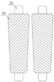
As a still further scheme of the invention: the compression roller sets up to the round platform form, churn outside fixedly connected with second puddler, the compression roller sets up to the round platform form and is favorable to carrying out the pertinence to not unidimensional material and rolls to improve the efficiency that rolls.
As a still further scheme of the invention: the slide bar is far away from baffle one end fixedly connected with montant, the montant outside is rotated and is connected with the sleeve, sleeve roll connection is in the limiting plate outside, the limiting plate surface is provided with the spacing groove that runs through, the slide bar passes through spacing groove and limiting plate sliding connection, slide bar outside fixedly connected with keeps off the ring, the spring sets up between limiting plate and fender ring, fixedly connected with branch between limiting plate and the box, the sleeve is favorable to changing the sliding connection between montant and the limiting plate into roll connection to make the slide bar can the steady removal.
As a still further scheme of the invention: the equal fixedly connected with riser in box top both sides, the quantity of riser sets up to a plurality ofly, adjacent two fixedly connected with guide bar between the riser, the equal fixedly connected with guide block in sliding frame both sides, the guide bar run through the guide block and with guide block sliding connection, utilize the guide bar to run through the guide block and with guide block sliding connection, be favorable to improving the stability of sliding frame motion.
As a still further scheme of the invention: the sliding frame is fixedly connected with a stabilizing plate on one side close to the connecting shaft, the connecting shaft penetrates through the stabilizing plate and is rotatably connected with the stabilizing plate, and the rack bottom end is fixedly connected with a support which is favorable for fixing the rack.
As a still further scheme of the invention: the bottom end of the interior of the box body is fixedly connected with a material guide plate, the material guide plate is arranged in an inclined mode, a through groove penetrating through the box body is formed in the top of the box body, and the sliding frame is connected with the box body in a sliding mode through a sliding groove.
Compared with the prior art, the invention has the beneficial effects that:
1. according to the invention, the raw materials in the sliding frame can be stirred by the first stirring rod, so that some raw materials with smaller size can be stirred to the bottom end of the sliding frame and can be discharged through a gap between the two baffles, the distance between the two baffles can be increased by extruding the vertical rod by the limiting plate, the materials with larger size can be discharged to the outer side of the sliding frame, the raw materials with smaller size can be arranged at the position with smaller distance between the two press rollers by arranging the press rollers in a circular table shape, so that the raw materials with smaller size can be rolled, some materials with larger size can fall to the position with larger distance between the two press rollers, the materials can be automatically classified according to size, the materials with different sizes can be rolled in a targeted manner, the rolling efficiency is improved, the crushing effect is improved, and the materials falling from the press rollers can be continuously crushed by rotating the second stirring rod, thereby further improving the pulverization effect.
2. According to the invention, the guide rod is arranged, the guide rod penetrates through the guide block and is in sliding connection with the guide block, so that the stability of the movement of the sliding frame is favorably improved, the bottom end inside the box body is fixedly connected with the material guide plate, the crushed material can be discharged through the material guide plate, and the material collection is favorably realized.
Drawings
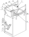
FIG. 1 is a schematic view of the overall structure of the present invention;
FIG. 2 is a schematic perspective view of the present invention;
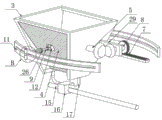
FIG. 3 is a schematic view of the baffle structure of the present invention;
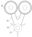
FIG. 4 is a diagram of a distribution of the rolls and mixing drum of the present invention;
FIG. 5 is a schematic view of a press roll configuration of the present invention;
FIG. 6 is an enlarged view of the portion A of FIG. 1 according to the present invention;
FIG. 7 is an enlarged view of the portion B of FIG. 3 according to the present invention.
In the figure: 1. a box body; 2. a discharge port; 3. a sliding frame; 4. a baffle plate; 5. a rotating shaft; 6. a first stirring rod; 7. a rack; 8. a connecting shaft; 9. a slide bar; 10. a spring; 11. a limiting plate; 12. a first connection block; 13. a second connecting block; 14. a first motor; 15. a screw rod; 16. a slider; 17. a support bar; 18. a second motor; 19. a drive shaft; 20. a compression roller; 21. a mixing drum; 22. a first circular shaft; 23. a belt; 24. a second stirring rod; 25. a sleeve; 26. a baffle ring; 27. a guide bar; 28. a guide block; 29. a stabilizing plate; 30. a through groove.
Detailed Description
The technical solutions in the embodiments of the present invention will be clearly and completely described below with reference to the drawings in the embodiments of the present invention, and it is obvious that the described embodiments are only a part of the embodiments of the present invention, and not all of the embodiments. All other embodiments, which can be derived by a person skilled in the art from the embodiments given herein without making any creative effort, shall fall within the protection scope of the present invention.
Referring to fig. 1 to 7, in the embodiment of the present invention, a production apparatus for preparing a recycled building material from building waste includes a box body 1, a material guide plate is fixedly connected to a bottom end inside the box body 1, the material guide plate is disposed in an inclined manner, a through groove 30 is disposed at a top of the box body 1, a sliding frame 3 is slidably connected to the box body 1 through a sliding groove, a plurality of vertical plates are fixedly connected to two sides of the top of the box body 1, a guide rod 27 is fixedly connected between two adjacent vertical plates, a guide block 28 is fixedly connected to two sides of the sliding frame 3, the guide rod 27 penetrates the guide block 28 and is slidably connected to the guide block 28, so as to improve the stability of the movement of the sliding frame 3, a discharge port 2 is disposed at one side of the box body 1, a power, the two sides of the feeding assembly are both provided with limiting assemblies, and a transmission assembly capable of driving the feeding assembly to reciprocate is arranged in the box body 1;
the feeding assembly comprises a sliding frame 3, a baffle plate 4, a rotating shaft 5, a first stirring rod 6, a rack 7 and a connecting shaft 8, wherein the baffle plate 4 is arranged at two sides of the sliding frame 3 and is hinged with the sliding frame 3, the rotating shaft 5 is rotatably connected inside the sliding frame 3, the first stirring rod 6 is fixedly connected outside the rotating shaft 5, one end of the rotating shaft 5 penetrates through the sliding frame 3 and extends to the outside of the sliding frame 3, the connecting shaft 8 is arranged at one end of the rotating shaft 5 extending to the outside of the sliding frame 3, one end of the rotating shaft 5 extending to the outside of the sliding frame 3 is fixedly connected with a first bevel gear, one end of the connecting shaft 8 close to the rotating shaft 5 is fixedly connected with a second bevel gear meshed with the first bevel gear, the rack 7 is arranged at one end of the connecting shaft 8 far away from the rotating shaft 5, one end of the connecting shaft 8 far away from the rotating shaft 5 is fixedly connected with a straight, the bottom end of the rack 7 is fixedly connected with a bracket, and the bracket is favorable for fixing the rack 7;
the limiting assembly comprises a sliding rod 9, a spring 10 and a limiting plate 11, wherein a first connecting block 12 is fixedly connected to each of two sides of the baffle 4, a second connecting block 13 is hinged to the outer side of the first connecting block 12, one end, close to the baffle 4, of the sliding rod 9 is hinged to the second connecting block 13, the limiting plate 11 is arranged at one end, far away from the baffle 4, of the sliding rod 9, a vertical rod is fixedly connected to one end, far away from the baffle 4, of the sliding rod 9, the outer side of the vertical rod is rotatably connected with a sleeve 25, the sleeve 25 is connected to the outer side of the limiting plate 11 in a rolling mode, a penetrating limiting groove is formed in the surface of the limiting plate 11, the sliding rod 9 is connected with the limiting plate 11 in a sliding mode through the limiting groove, a retaining ring 26 is fixedly connected to the outer side of the sliding rod 9, the spring 10 is arranged outside the slide rod 9, the slide rod 9 penetrates through the limit plate 11 and is in sliding connection with the limit plate 11, and the limit plate 11 is in an arc shape.
The transmission assembly comprises a first motor 14, a screw rod 15 and a sliding block 16, the sliding block 16 is arranged at the bottom end of the sliding frame 3, supporting rods 17 are arranged on two sides of the sliding block 16, the supporting rods 17 are fixedly connected between the sliding block 16 and the sliding frame 3, the screw rod 15 penetrates through the sliding block 16 and is in threaded connection with the sliding block 16, the screw rod 15 is fixedly connected with the output end of the first motor 14, a first base is fixedly connected with the bottom of the first motor 14, the output end of the first motor 14 drives the screw rod 15 to rotate, and the sliding block 16 is driven to move in the.
The power assembly comprises a second motor 18, a transmission shaft 19, a press roller 20 and a mixing drum 21, the transmission shaft 19 is fixedly connected with the output end of the second motor 18, the press roller 20 and the mixing drum 21 are fixedly connected with a first round shaft 22 near one end of the second motor 18, the press roller 20 is in a round table shape, a second mixing rod 24 is fixedly connected with the outer side of the mixing drum 21, the press roller 20 is in a round table shape, which is beneficial to performing targeted rolling on materials with different sizes, so that the rolling efficiency is improved, one end of the press roller 20 and one end of the mixing drum 21 far away from the second motor 18 are fixedly connected with a second round shaft, belt wheels are fixedly connected with the outer sides of the first round shaft 22 and the transmission shaft 19, belts 23 are sleeved on the outer sides of the belt wheels, the press roller 20 and the mixing drum 21 are rotatably connected with the box body 1 through the second round shaft, a second base is, the material is favorably crushed by the belt 23 driving the press roll 20 and the mixing drum 21 to rotate.
The working principle of the invention is as follows: the feeding assembly is arranged at the top end of the box body 1, materials to be processed are conveyed into the sliding frame 3 during use, the baffle plates 4 are hinged to two sides of the sliding frame 3, the bottom ends of the two baffle plates 4 are close to each other, so that small materials in the materials can be discharged through a gap between the two baffle plates 4, meanwhile, the output end of the first motor 14 drives the screw rod 15 to rotate, the screw rod 15 penetrates through the sliding block 16 and is in threaded connection with the sliding block 16, the sliding block 16 can be driven to move in the horizontal direction through the rotation of the screw rod 15, the sliding block 16 can drive the sliding frame 3 to move in the horizontal direction through the fixedly connected supporting rod 17 between the sliding block 16 and the sliding frame 3, the sliding frame 3 can drive the connecting shaft 8 to move, the straight gear can be driven to rotate through the meshing of the straight gear and the rack 7, the connecting shaft 8 can drive the rotating, the rotating shaft 5 can drive the first stirring rod 6 at the outer side to rotate, so that raw materials in the sliding frame 3 are stirred, some raw materials with smaller sizes can be stirred to the bottom end of the sliding frame 3 and are discharged through a gap between the two baffles 4 easily, the sliding frame 3 can drive the sliding rods 9 at two sides to move, the sliding rods 9 can drive the vertical rods at one ends to move, the vertical rods can be extruded by the limiting plates 11 in the moving process, the sleeves 25 are arranged at the outer sides of the vertical rods, the sliding connection between the vertical rods and the limiting plates 11 is favorably changed into rolling connection, so that the sliding rods 9 can stably move, the sliding rods 9 can be driven to slide outwards by the extrusion of the limiting plates 11 on the vertical rods, the baffles 4 are driven to rotate outwards, the distance between the two baffles 4 is increased, and materials with larger sizes can be discharged to the outer side of the sliding frame 3, the second motor 18 is arranged, the output end of the second motor 18 drives the transmission shaft 19 to rotate, the transmission shaft 19 can drive the first round rod to rotate through the matching of the belt 23 and the belt wheel, the compression roller 20 and the mixing drum 21 are driven to rotate, the compression roller 20 is in a round table shape, the distance between the parts, close to the second motor 18, of the compression roller 20 is smaller, the distance between the parts, far away from the motor is larger, when blanking is started, because the distance between the bottom ends of the two baffles 4 is smaller, the small-sized raw materials can be arranged at the parts, with the smaller distance between the two compression rollers 20, of the small-sized raw materials can be rolled, after the sliding frame 3 moves for a period of time, the distance between the bottom ends of the two baffles 4 is gradually increased, some large-sized materials can fall down to the parts, with the larger distance between the two compression rollers 20, the materials can be rolled, thereby can carry out the pertinence to the material of equidimension not and roll to improve the efficiency that rolls, be favorable to improving the effect that crushes, the material that drops from compression roller 20 rotates through second puddler 24 and can continue to smash it, thereby can further improve crushing effect.
The above description is only for the preferred embodiment of the present invention, but the scope of the present invention is not limited thereto, and any person skilled in the art should be considered to be within the technical scope of the present invention, and the technical solutions and the inventive concepts thereof according to the present invention should be equivalent or changed within the scope of the present invention.
Claims (8)
1. The utility model provides a construction waste preparation regeneration building material's production facility, includes box (1), box (1) one side is provided with discharge gate (2), box (1) one side is provided with power component, its characterized in that: the top of the box body (1) is connected with a feeding assembly in a sliding mode, two sides of the feeding assembly are provided with limiting assemblies, and a transmission assembly capable of driving the feeding assembly to reciprocate is arranged in the box body (1);
the feeding assembly comprises a sliding frame (3), baffles (4), a rotating shaft (5), a first stirring rod (6), a rack (7) and a connecting shaft (8), wherein the baffles (4) are arranged on two sides of the sliding frame (3) and hinged with the sliding frame (3), the rotating shaft (5) is rotatably connected inside the sliding frame (3), the first stirring rod (6) is fixedly connected to the outer side of the rotating shaft (5), one end of the rotating shaft (5) penetrates through the sliding frame (3) and extends to the outer side of the sliding frame (3), the connecting shaft (8) is arranged at one end of the rotating shaft (5) extending to the outer side of the sliding frame (3), one end of the rotating shaft (5) extending to the outer side of the sliding frame (3) is fixedly connected with a first bevel gear, one end of the connecting shaft (8) close to the rotating shaft (5) is fixedly connected with a second bevel gear meshed with the first bevel gear, and the rack (7) is arranged at one end of the connecting, one end of the connecting shaft (8) far away from the rotating shaft (5) is fixedly connected with a straight gear meshed with the rack (7);
spacing subassembly includes slide bar (9), spring (10) and limiting plate (11), baffle (4) both sides equal fixedly connected with first connecting block (12), first connecting block (12) outside articulates there is second connecting block (13), slide bar (9) are close to baffle (4) one end and are articulated with second connecting block (13), limiting plate (11) set up and keep away from baffle (4) one end in slide bar (9), spring (10) set up in the slide bar (9) outside, slide bar (9) run through limiting plate (11) and with limiting plate (11) sliding connection, limiting plate (11) set up to circular-arcly.
2. The manufacturing equipment for preparing recycled building materials from construction wastes according to claim 1, characterized in that: the transmission assembly comprises a first motor (14), a screw rod (15) and a sliding block (16), the sliding block (16) is arranged at the bottom end of the sliding frame (3), supporting rods (17) are arranged on two sides of the sliding block (16), the supporting rods (17) are fixedly connected between the sliding block (16) and the sliding frame (3), the screw rod (15) penetrates through the sliding block (16) and is in threaded connection with the sliding block (16), the screw rod (15) is fixedly connected with the output end of the first motor (14), and a first base is fixedly connected to the bottom of the first motor (14).
3. The manufacturing equipment for preparing recycled building materials from construction wastes according to claim 1, characterized in that: the power assembly comprises a second motor (18), a transmission shaft (19), a compression roller (20) and a mixing drum (21), the transmission shaft (19) is fixedly connected with the output end of the second motor (18), the compression roller (20) and the mixing drum (21) are close to a first round shaft (22) of one end of the second motor (18) fixedly connected with, the compression roller (20) and the mixing drum (21) are far away from a second round shaft of one end fixedly connected with of the second motor (18), the first round shaft (22) and the transmission shaft (19) are fixedly connected with belt pulleys on the outer side, a belt (23) is sleeved on the outer side of each belt pulley, the compression roller (20) and the mixing drum (21) are connected with the box body (1) in a rotating mode through the second round shaft, and the second motor (18) is fixedly connected with a second base.
4. The manufacturing equipment for preparing recycled building materials from construction wastes according to claim 3, characterized in that: the pressing roller (20) is in a circular truncated cone shape, and a second stirring rod (24) is fixedly connected to the outer side of the stirring cylinder (21).
5. The manufacturing equipment for preparing recycled building materials from construction wastes according to claim 1, characterized in that: baffle (4) one end fixedly connected with montant is kept away from in slide bar (9), the montant outside is rotated and is connected with sleeve (25), sleeve (25) roll connection is in the limiting plate (11) outside, limiting plate (11) surface is provided with the spacing groove that runs through, slide bar (9) are through spacing groove and limiting plate (11) sliding connection, slide bar (9) outside fixedly connected with keeps off ring (26), spring (10) set up in limiting plate (11) and keep off between ring (26), fixedly connected with branch between limiting plate (11) and box (1).
6. The manufacturing equipment for preparing recycled building materials from construction wastes according to claim 1, characterized in that: the box (1) top both sides all fixedly connected with riser, the quantity of riser sets up to a plurality ofly, adjacent two fixedly connected with guide bar (27) between the riser, the equal fixedly connected with guide block (28) in smooth frame (3) both sides, guide bar (27) run through guide block (28) and with guide block (28) sliding connection.
7. The manufacturing equipment for preparing recycled building materials from construction wastes according to claim 1, characterized in that: slide frame (3) are close to connecting axle (8) one side fixedly connected with steadying plate (29), connecting axle (8) run through steadying plate (29) and rotate with steadying plate (29) and be connected, rack (7) bottom fixedly connected with support.
8. The manufacturing equipment for preparing recycled building materials from construction wastes according to claim 1, characterized in that: the material guide plate is fixedly connected to the bottom end inside the box body (1) and is obliquely arranged, a through groove (30) penetrating through the box body (1) is formed in the top of the box body (1), and the sliding frame (3) is connected with the box body (1) in a sliding mode through a sliding groove.
Priority Applications (1)
| Application Number | Priority Date | Filing Date | Title |
|---|---|---|---|
| CN202010796998.6A CN111905865B (en) | 2020-08-10 | 2020-08-10 | Production equipment for preparing recycled building material from building waste |
Applications Claiming Priority (1)
| Application Number | Priority Date | Filing Date | Title |
|---|---|---|---|
| CN202010796998.6A CN111905865B (en) | 2020-08-10 | 2020-08-10 | Production equipment for preparing recycled building material from building waste |
Publications (2)
| Publication Number | Publication Date |
|---|---|
| CN111905865A true CN111905865A (en) | 2020-11-10 |
| CN111905865B CN111905865B (en) | 2023-01-06 |
Family
ID=73283567
Family Applications (1)
| Application Number | Title | Priority Date | Filing Date |
|---|---|---|---|
| CN202010796998.6A Active CN111905865B (en) | 2020-08-10 | 2020-08-10 | Production equipment for preparing recycled building material from building waste |
Country Status (1)
| Country | Link |
|---|---|
| CN (1) | CN111905865B (en) |
Cited By (1)
| Publication number | Priority date | Publication date | Assignee | Title |
|---|---|---|---|---|
| CN115178367A (en) * | 2022-09-12 | 2022-10-14 | 泉州市风火轮机械设备有限公司 | Circulating type roller sand crusher |
Citations (5)
| Publication number | Priority date | Publication date | Assignee | Title |
|---|---|---|---|---|
| CH572767A5 (en) * | 1973-12-06 | 1976-02-27 | Buehler Ag Geb | |
| CN207981289U (en) * | 2018-01-22 | 2018-10-19 | 广州市鸿鼎景观设计工程有限公司 | Fiber glass waste breaker |
| WO2019159119A1 (en) * | 2018-02-15 | 2019-08-22 | Flsmidth A/S | Comminution device feed mechanism and method |
| CN210022365U (en) * | 2019-02-02 | 2020-02-07 | 山东荣泰建筑工程集团有限公司 | A reducing mechanism for building rubbish |
| CN111167552A (en) * | 2020-01-02 | 2020-05-19 | 金陵科技学院 | Waste treatment equipment for recovered LED lamps and operation method |
-
2020
- 2020-08-10 CN CN202010796998.6A patent/CN111905865B/en active Active
Patent Citations (5)
| Publication number | Priority date | Publication date | Assignee | Title |
|---|---|---|---|---|
| CH572767A5 (en) * | 1973-12-06 | 1976-02-27 | Buehler Ag Geb | |
| CN207981289U (en) * | 2018-01-22 | 2018-10-19 | 广州市鸿鼎景观设计工程有限公司 | Fiber glass waste breaker |
| WO2019159119A1 (en) * | 2018-02-15 | 2019-08-22 | Flsmidth A/S | Comminution device feed mechanism and method |
| CN210022365U (en) * | 2019-02-02 | 2020-02-07 | 山东荣泰建筑工程集团有限公司 | A reducing mechanism for building rubbish |
| CN111167552A (en) * | 2020-01-02 | 2020-05-19 | 金陵科技学院 | Waste treatment equipment for recovered LED lamps and operation method |
Cited By (1)
| Publication number | Priority date | Publication date | Assignee | Title |
|---|---|---|---|---|
| CN115178367A (en) * | 2022-09-12 | 2022-10-14 | 泉州市风火轮机械设备有限公司 | Circulating type roller sand crusher |
Also Published As
| Publication number | Publication date |
|---|---|
| CN111905865B (en) | 2023-01-06 |
Similar Documents
| Publication | Publication Date | Title |
|---|---|---|
| CN210496574U (en) | Waste material reducing mechanism | |
| CN113185164B (en) | Method for preparing recycled concrete fine aggregate by using building brick-concrete waste | |
| CN111686859B (en) | Building waste environmental protection processing apparatus | |
| CN110756562B (en) | Urban solid waste treatment equipment | |
| CN211412662U (en) | Industrial waste classification device | |
| CN114798112A (en) | New energy automobile battery recovery unit | |
| CN107790220A (en) | A kind of litter decoration apparatus for crushing and treating | |
| CN111468231A (en) | Roller press for fly ash production | |
| CN111905865B (en) | Production equipment for preparing recycled building material from building waste | |
| CN213730692U (en) | Scrap recovery device for steel nail production equipment | |
| CN110711625B (en) | Automatic change waste material processing apparatus | |
| CN210646569U (en) | Pottery garbage collection device | |
| CN210386162U (en) | Modified starch processing material feeding unit | |
| CN216172738U (en) | Building rubbish breaker for building engineering | |
| CN214554278U (en) | High-yield ore raw material processing device | |
| CN216260633U (en) | High-pressure paired-roller ball press | |
| CN212681995U (en) | Construction waste recycling concrete block passivation treatment device | |
| CN114177987A (en) | Smashing device for plastic products | |
| CN210619181U (en) | Glass processing production line glass recovery unit that gives up | |
| CN2411057Y (en) | double-acting jaws high energy crushing mechanism | |
| CN214916438U (en) | Processing device for recycling construction waste | |
| CN217747296U (en) | Reducing mechanism of aluminium sulfate production | |
| CN219501568U (en) | Automatic pill forming machine | |
| CN213854812U (en) | Rubbing crusher with screening function | |
| CN210816211U (en) | Biomass fuel processing device |
Legal Events
| Date | Code | Title | Description |
|---|---|---|---|
| PB01 | Publication | ||
| PB01 | Publication | ||
| SE01 | Entry into force of request for substantive examination | ||
| SE01 | Entry into force of request for substantive examination | ||
| TA01 | Transfer of patent application right | ||
| TA01 | Transfer of patent application right |
Effective date of registration: 20221221 Address after: 350000 factory building of Shima office at the back of the mountain in Shangqi village, Gaishan Town, Cangshan District, Fuzhou City, Fujian Province Applicant after: Fujian Guozhuang Concrete Co.,Ltd. Address before: 315100 Linjia industrial zone at the intersection of Siming East Road and Dongyu Road, Yinzhou District, Ningbo City, Zhejiang Province Applicant before: Meng Yuanhang |
|
| GR01 | Patent grant | ||
| GR01 | Patent grant |