CN111895094B - Oil sealing structure for automobile engine - Google Patents
Oil sealing structure for automobile engine Download PDFInfo
- Publication number
- CN111895094B CN111895094B CN202010573867.1A CN202010573867A CN111895094B CN 111895094 B CN111895094 B CN 111895094B CN 202010573867 A CN202010573867 A CN 202010573867A CN 111895094 B CN111895094 B CN 111895094B
- Authority
- CN
- China
- Prior art keywords
- oil return
- oil
- rear end
- end shaft
- groove
- Prior art date
- Legal status (The legal status is an assumption and is not a legal conclusion. Google has not performed a legal analysis and makes no representation as to the accuracy of the status listed.)
- Active
Links
Images


Classifications
-
- F—MECHANICAL ENGINEERING; LIGHTING; HEATING; WEAPONS; BLASTING
- F16—ENGINEERING ELEMENTS AND UNITS; GENERAL MEASURES FOR PRODUCING AND MAINTAINING EFFECTIVE FUNCTIONING OF MACHINES OR INSTALLATIONS; THERMAL INSULATION IN GENERAL
- F16J—PISTONS; CYLINDERS; SEALINGS
- F16J15/00—Sealings
- F16J15/16—Sealings between relatively-moving surfaces
- F16J15/32—Sealings between relatively-moving surfaces with elastic sealings, e.g. O-rings
- F16J15/3204—Sealings between relatively-moving surfaces with elastic sealings, e.g. O-rings with at least one lip
-
- F—MECHANICAL ENGINEERING; LIGHTING; HEATING; WEAPONS; BLASTING
- F16—ENGINEERING ELEMENTS AND UNITS; GENERAL MEASURES FOR PRODUCING AND MAINTAINING EFFECTIVE FUNCTIONING OF MACHINES OR INSTALLATIONS; THERMAL INSULATION IN GENERAL
- F16N—LUBRICATING
- F16N31/00—Means for collecting, retaining, or draining-off lubricant in or on machines or apparatus
- F16N31/02—Oil catchers; Oil wipers
Abstract
The invention relates to the technical field of oil sealing structures, and discloses an oil sealing structure for an automobile engine, which comprises an oil seal assembly and a rear end shaft, wherein the oil seal assembly is provided with a sealing lip, the sealing lip is sleeved on the peripheral surface of the rear end shaft, an oil return groove is arranged on the peripheral surface of the rear end shaft, the oil return groove is in a threaded shape, a first end of the oil return groove is arranged on one side, facing the inside of the engine, of the sealing lip, a second end of the oil return groove extends to the end surface, located on the inside of the engine, of the rear end shaft, and the spiral line direction of the oil return groove is opposite to the rotation direction of the rear end shaft. By arranging the oil return groove, the phenomenon that engine oil is deposited on one side, facing the interior of the engine, of the sealing lip can be relieved, oil leakage of the engine is avoided, and a good anti-seepage effect is achieved.
Description
Technical Field
The invention relates to the technical field of oil sealing structures, in particular to an oil sealing structure for an automobile engine.
Background
Referring to fig. 1, the oil seal assembly 100 is disposed on the circumferential surface of the rear end shaft 200 of the crankshaft 300 of the automobile engine, the oil seal assembly 100 is sleeved outside the rear end shaft 200 of the crankshaft 300, the oil seal assembly 100 is provided with a rubber seal lip 101, the seal lip 101 is wrapped on the circumferential surface of the rear end shaft 200, and the circumferential surface of the rear end shaft 200 has a certain roughness. With this arrangement, the seal lip 101 has a certain holding force against the circumferential surface of the rear end shaft 200, and can block the engine oil and prevent the oil leakage.
However, after the engine operates for a period of time, the rubber of the seal lip 101 is aged, which causes the holding force of the seal lip 101 to decrease, and the rubber is aged, which causes cracks of the seal lip 101 itself, so that when oil is accumulated on the side of the seal lip 101 facing the inside of the engine, the oil can flow to the outside of the engine through the oil seal assembly 100, which causes oil leakage of the engine.
Disclosure of Invention
The purpose of the invention is: the utility model provides a phenomenon that is used for automobile engine's oil sealing structure, machine oil is at the inside one side siltation of seal lip towards the engine is alleviated to avoid the engine oil leak.
In order to achieve the above object, the present invention provides an oil sealing structure for an automobile engine, including an oil seal assembly and a rear end shaft, where the oil seal assembly is provided with a sealing lip, the sealing lip is sleeved on a circumferential surface of the rear end shaft, the circumferential surface of the rear end shaft is provided with an oil return groove, the oil return groove is in a thread shape, a first end of the oil return groove is arranged on one side of the sealing lip facing the inside of the engine, a second end of the oil return groove extends to an end surface of the rear end shaft located inside the engine, and a spiral line direction of the oil return groove is opposite to a rotation direction of the rear end shaft.
Optionally, a distance between one end of the oil return groove close to the seal lip and the seal lip is recorded as a first distance L, a diameter of the rear end shaft is recorded as a shaft diameter D, and a relationship between the first distance L and the shaft diameter D is: l is more than or equal to 0.2D and less than or equal to D.
Optionally, when the oil return groove rotates around the circumferential surface of the rear end shaft, the axial distance between the two ends of the oil return groove is recorded as a pitch P, and the relationship between the pitch P and the shaft diameter D is as follows: p is more than or equal to 1.2D and less than or equal to 2D.
Optionally, the shaft diameter D is greater than 40mm, the number of the oil return grooves is 4, the first end of each oil return groove is located on the same cross section of the rear end shaft, and the first ends of the oil return grooves are uniformly arranged.
Optionally, the shaft diameter D is 30mm to 40mm, the number of the oil return grooves is 3, the first ends of the oil return grooves are located on the same cross section of the rear end shaft, and the first ends of the oil return grooves are uniformly arranged.
Optionally, the shaft diameter D is 20mm to 30mm, the number of the oil return grooves is 2, the first ends of the oil return grooves are located on the same cross section of the rear end shaft, and the first ends of the oil return grooves are uniformly arranged.
Optionally, the shaft diameter D is smaller than 20mm, and the number of the oil return grooves is 1.
Optionally, two ends of the oil return groove gradually transition to the circumferential surface of the rear end shaft from the groove bottom.
Optionally, two ends of the oil return groove are transited to the circumferential surface of the rear end shaft from the groove bottom in an arc shape, and the radius of the arc shape is between 3mm and 8 mm.
Optionally, the depth of the oil return groove is recorded as a groove depth H, and the size of the groove depth H is as follows: h is more than or equal to 0.5mm and less than or equal to 1 mm.
Compared with the prior art, the oil sealing structure for the automobile engine has the beneficial effects that:
the oil seal structure for the automobile engine comprises an oil seal assembly and a rear end shaft, wherein the oil seal assembly is provided with a seal lip, the seal lip is sleeved on the circumferential surface of the rear end shaft, an oil return groove is formed in the circumferential surface of the rear end shaft, the oil return groove is in a threaded shape, a first end of the oil return groove is arranged on one side, facing the interior of the engine, of the seal lip, a second end of the oil return groove extends to the end surface, located in the interior of the engine, of the rear end shaft, and the spiral line direction of the oil return groove is opposite to the rotating direction of the rear end shaft. Through setting up the oil gallery, the machine oil of depositing towards the inside one side siltation of engine at the seal lip can get into the oil gallery originally, and when the bent axle was rotatory, the machine oil of siltation received bent axle's effort, and machine oil can move to the second end of oil gallery in the oil gallery to inside the reflux engine, thereby alleviate the phenomenon of machine oil at the seal lip towards the inside one side siltation of engine, and then avoid the engine oil leak.
Drawings
FIG. 1 is a schematic diagram of a prior art engine crankshaft configuration.
Fig. 2 is a schematic structural diagram of an oil seal structure at a position a in the prior art.
Fig. 3 is a schematic structural diagram of an embodiment of the present invention.
FIG. 4 is a schematic view of a rear end shaft of an embodiment of the present invention.
FIG. 5 is a schematic view of an embodiment of the present invention with a rear end shaft diameter less than 20 mm.
FIG. 6 is a schematic view of an embodiment of the present invention having a rear end shaft diameter between 20mm and 30 mm.
FIG. 7 is a schematic view of an embodiment of the present invention having a rear end shaft diameter between 30mm and 40 mm.
FIG. 8 is a schematic view of an embodiment of the present invention having a rear end shaft diameter greater than 40 mm.
Fig. 9 is a schematic view illustrating the processing of an oil return groove according to an embodiment of the present invention.
In the figure, 100, an oil seal assembly; 200. a rear end shaft; 300. a crankshaft; 101. a sealing lip;
1. a sealing lip; 2. a rear end shaft; 3. a crankshaft; 21. an oil return groove.
Detailed Description
The following detailed description of embodiments of the present invention is provided in connection with the accompanying drawings and examples. The following examples are intended to illustrate the invention but are not intended to limit the scope of the invention.
In describing the present invention, it should be understood that the term "rear end shaft" is used herein to generally refer to the output end of the engine crankshaft. In the description of the present invention, it should be noted that the terms "center", "longitudinal", "lateral", "upper", "lower", "front", "rear", "left", "right", "vertical", "horizontal", "top", "bottom", "inner", "outer", etc. indicate orientations or positional relationships based on those shown in the drawings, and are only for convenience of description and simplicity of description, but do not indicate or imply that the referred apparatus or element must have a specific orientation, be constructed and operated in a specific orientation, and thus, should not be construed as limiting the present invention. Furthermore, the terms "first," "second," and "third" are used for descriptive purposes only and are not to be construed as indicating or implying relative importance.
In the description of the present invention, it should be noted that, unless otherwise explicitly specified or limited, the terms "mounted," "connected," and "connected" are to be construed broadly, e.g., as meaning either a fixed connection, a removable connection, or an integral connection; can be mechanically or electrically connected; they may be connected directly or indirectly through intervening media, or they may be interconnected between two elements. The specific meanings of the above terms in the present invention can be understood in specific cases to those skilled in the art.
The specific meanings of the above terms in the present invention can be understood in specific cases to those skilled in the art.
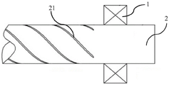
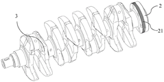
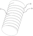
Referring to fig. 3 to 4, an oil sealing structure for an automobile engine according to a preferred embodiment of the present invention includes an oil seal assembly and a rear end shaft 2, the oil seal assembly is provided with a seal lip 1, the seal lip 1 is sleeved on a circumferential surface of the rear end shaft 2, an oil return groove 21 is provided on the circumferential surface of the rear end shaft 2, the oil return groove 21 is in a thread shape, a first end of the oil return groove 21 is disposed on a side of the seal lip 1 facing an interior of the engine, a second end of the oil return groove 21 extends to an end surface of the rear end shaft 2 located in the interior of the engine, and a spiral line direction of the oil return groove 21 is opposite to a rotation direction of the rear end shaft 2. In fig. 3, the left side of the seal lip 1 is the inside of the engine, and the right side of the seal lip 1 is the outside of the engine. When the crankshaft 3 rotates, part of the engine oil is thrown to the inner side of the seal lip 1 and gradually flows down to the peripheral surface of the rear end shaft 2. The oil return groove 21 is provided, and oil that would otherwise accumulate on the side of the seal lip 1 facing the inside of the engine enters the oil return groove 21. While the crankshaft 3 rotates, the accumulated oil is subjected to the force of the crankshaft 3, and the force causes the oil to move in the oil return groove 21 in both the axial direction and the radial direction, so that the oil can move to the second end of the oil return groove 21 in the oil return groove 21 and return to the inside of the engine. In the structure shown in fig. 3 of this embodiment, the acting force applied to the oil in the oil return groove 21 can drive the oil to have an axial speed toward the left, in the radial speed direction, the central axis of the rear end shaft 2 is used as a boundary, the circumferential motion direction of the oil in the upper half oil return groove 21 is inward of the plane of the vertical drawing, and the circumferential motion direction of the oil in the lower half oil return groove 21 is outward of the plane of the vertical drawing. Therefore, the phenomenon that the engine oil is accumulated on one side of the sealing lip 1 facing the inside of the engine is relieved, and the engine oil flows towards the inside of the engine, so that the engine oil leakage is avoided. Furthermore, by providing the oil return groove 21, the requirement for the roughness of the peripheral surface of the rear end shaft 2 is reduced, and the processing cost is reduced.
Wherein, note that the axial distance at oil gallery 21 both ends is pitch P when oil gallery 21 rotates a week along the global of rear end axle 2, and pitch P and the relation of axle footpath D are: p is more than or equal to 1.2D and less than or equal to 2D. This dimension enables most of the oil to flow back into the engine via the oil return channel 21, without being thrown out of the oil return channel 21 and without the oil flowing out of the second end of the oil return channel 21. Both ends of the oil return groove 21 gradually transition from the groove bottom to the circumferential surface of the rear end shaft 2. This arrangement facilitates both easy entry of oil into the first end of the oil return channel 21 and exit of oil from the second end of the oil return channel 21 from the oil return channel 21. Referring to fig. 9, two ends of the oil return groove 21 are arc-shaped transited from the groove bottom to the circumferential surface of the rear end shaft 2, and the arc radius is recorded as R, and the arc radius R is between 3mm and 8 mm. Multiple practices show that the arc-shaped effect is good, the engine oil moving speed is high when the radius R is between 3mm and 8mm, and engine oil accumulation cannot occur on one side, facing the inside of an engine, of the sealing lip 1. In this embodiment, the depth of the oil returning groove 21 is defined as a groove depth H, and the dimensions of the groove depth H are: h is more than or equal to 0.5mm and less than or equal to 1 mm. This size range enables most of the oil to flow back into the engine through the oil return groove 21 without being thrown out of the oil return groove 21 and without having too wide a groove depth. Note that the distance between the end of the oil return groove 21 close to the seal lip 1 and the seal lip 1 is a first distance L, note that the diameter of the rear end shaft 2 is a shaft diameter D, and the relationship between the first distance L and the shaft diameter D is: l is more than or equal to 0.2D and less than or equal to D. By the arrangement, the oil return groove 21 can not be contacted with the sealing lip 1, and the sealing effect of the sealing lip 1 is prevented from being influenced.
Referring to fig. 5, when the diameter D of the shaft is smaller than 20mm, the number of the oil return grooves 21 is 1, so as to meet the requirement of engine leakage prevention. Referring to fig. 6, when the shaft diameter D is between 20mm and 30mm, the number of the oil return grooves 21 is 2, the first ends of the oil return grooves 21 are all located on the same cross section of the rear end shaft 2, and the first ends of the oil return grooves 21 are uniformly arranged, so that the requirement of engine leakage prevention can be met. Referring to fig. 7, when the shaft diameter D is 30mm-40mm, the number of the oil return grooves 21 is 3, the first ends of the oil return grooves 21 are all located on the same cross section of the rear end shaft 2, and the first ends of the oil return grooves 21 are uniformly arranged, so that the requirement of engine leakage prevention can be met. Referring to fig. 8, when the shaft diameter D is greater than 40mm, the number of the oil return grooves 21 is 4, the first ends of the oil return grooves 21 are all located on the same cross section of the rear end shaft 2, and the first ends of the oil return grooves 21 are uniformly arranged, so that the requirement of engine leakage prevention can be met.
The working process of the invention is as follows: when the rear end shaft 2 rotates, the engine oil is thrown to the inner side of the seal lip 1, gradually flows down to the peripheral surface of the rear end shaft 2, then flows into the oil return groove 21 from the first end of the oil return groove 21, then moves in the oil return groove 21 until flowing to the second end of the oil return groove 21, and finally flows back to the interior of the engine from the second end of the oil return groove 21.
To sum up, the embodiment of the invention provides an oil sealing structure for an automobile engine, which can relieve the phenomenon that engine oil is deposited on one side of a sealing lip 1 facing the inside of the engine, avoid the engine oil leakage and have a better anti-leakage effect.
The above description is only a preferred embodiment of the present invention, and it should be noted that, for those skilled in the art, various modifications and substitutions can be made without departing from the technical principle of the present invention, and these modifications and substitutions should also be regarded as the protection scope of the present invention.
Claims (4)
1. An oil sealing structure for an automobile engine is characterized by comprising an oil seal assembly and a rear end shaft, wherein the oil seal assembly is provided with a sealing lip, the sealing lip is sleeved on the peripheral surface of the rear end shaft, an oil return groove is formed in the peripheral surface of the rear end shaft, the oil return groove is in a threaded shape, a first end of the oil return groove is arranged on one side, facing the interior of the engine, of the sealing lip, a second end of the oil return groove extends to the end surface, located in the interior of the engine, of the rear end shaft, and the spiral line direction of the oil return groove is opposite to the rotating direction of the rear end shaft;
recording the distance between one end, close to the seal lip, of the oil return groove and the seal lip as a first distance L, recording the diameter of the rear end shaft as a shaft diameter D, and recording the relationship between the first distance L and the shaft diameter D as follows: l is more than or equal to 0.2D and less than or equal to D, the axial distance between two ends of the oil return groove is recorded as a pitch P when the oil return groove rotates for a circle along the circumferential surface of the rear end shaft, and the relation between the pitch P and the shaft diameter D is as follows: p is more than or equal to 1.2D and less than or equal to 2D;
when the shaft diameter D is larger than 40mm, the number of the oil return grooves is 4, the first ends of the oil return grooves are located on the same cross section of the rear-end shaft, and the first ends of the oil return grooves are uniformly arranged;
when the shaft diameter D is between 30mm and 40mm, the number of the oil return grooves is 3, the first ends of the oil return grooves are located on the same cross section of the rear end shaft, and the first ends of the oil return grooves are uniformly arranged;
when the shaft diameter D is between 20mm and 30mm, the number of the oil return grooves is 2, the first ends of the oil return grooves are located on the same cross section of the rear-end shaft, and the first ends of the oil return grooves are uniformly arranged;
when the shaft diameter D is smaller than 20mm, the number of the oil return grooves is 1.
2. The oil seal structure for an automobile engine according to claim 1, wherein both ends of the oil return groove gradually transition from a groove bottom to a circumferential surface of the rear end shaft.
3. The oil seal structure for the automobile engine according to claim 2, wherein both ends of the oil return groove are transited from a groove bottom arc to the circumferential surface of the rear end shaft, and the radius of the arc is between 3mm and 8 mm.
4. The oil seal structure for an automobile engine according to claim 1, characterized in that the depth of the oil return groove is recorded as a groove depth H, and the dimension of the groove depth H is: h is more than or equal to 0.5mm and less than or equal to 1 mm.
Priority Applications (1)
| Application Number | Priority Date | Filing Date | Title |
|---|---|---|---|
| CN202010573867.1A CN111895094B (en) | 2020-06-22 | 2020-06-22 | Oil sealing structure for automobile engine |
Applications Claiming Priority (1)
| Application Number | Priority Date | Filing Date | Title |
|---|---|---|---|
| CN202010573867.1A CN111895094B (en) | 2020-06-22 | 2020-06-22 | Oil sealing structure for automobile engine |
Publications (2)
| Publication Number | Publication Date |
|---|---|
| CN111895094A CN111895094A (en) | 2020-11-06 |
| CN111895094B true CN111895094B (en) | 2022-09-13 |
Family
ID=73206920
Family Applications (1)
| Application Number | Title | Priority Date | Filing Date |
|---|---|---|---|
| CN202010573867.1A Active CN111895094B (en) | 2020-06-22 | 2020-06-22 | Oil sealing structure for automobile engine |
Country Status (1)
| Country | Link |
|---|---|
| CN (1) | CN111895094B (en) |
Families Citing this family (1)
| Publication number | Priority date | Publication date | Assignee | Title |
|---|---|---|---|---|
| CN113719612A (en) * | 2021-07-29 | 2021-11-30 | 岚图汽车科技有限公司 | Engine oil pan sealing structure, engine and automobile |
Citations (3)
| Publication number | Priority date | Publication date | Assignee | Title |
|---|---|---|---|---|
| CN206111863U (en) * | 2016-10-21 | 2017-04-19 | 攀钢集团工程技术有限公司 | Reducer shaft holds end cover |
| CN209196117U (en) * | 2018-12-21 | 2019-08-02 | 江西大唐国际新余发电有限责任公司 | The sealing of axle journal permeability |
| WO2020039982A1 (en) * | 2018-08-23 | 2020-02-27 | Nok株式会社 | Sealing device and method for making slinger |
Family Cites Families (10)
| Publication number | Priority date | Publication date | Assignee | Title |
|---|---|---|---|---|
| DE3418738C2 (en) * | 1984-05-19 | 1986-05-15 | Fa. Carl Freudenberg, 6940 Weinheim | Shaft seal |
| JPH02113173A (en) * | 1988-10-20 | 1990-04-25 | Nok Corp | Sealing device |
| DE19721692C2 (en) * | 1997-05-23 | 2000-02-24 | Freudenberg Carl Fa | Sealing arrangement |
| JP2001165327A (en) * | 1999-12-08 | 2001-06-22 | Koyo Sealing Techno Co Ltd | Sealing apparatus |
| JP2009257421A (en) * | 2008-04-15 | 2009-11-05 | Toyota Industries Corp | Shaft seal structure of fluid machine |
| JP6000845B2 (en) * | 2012-12-28 | 2016-10-05 | Nok株式会社 | Sealing device |
| CN106461086B (en) * | 2014-06-10 | 2019-01-15 | Nok株式会社 | sealing device |
| EP3382241A4 (en) * | 2015-11-24 | 2018-11-21 | NOK Corporation | Sealing device |
| CN109058463B (en) * | 2018-08-28 | 2019-12-24 | 浙江工业大学 | Wear-resistant rotary shaft lip-shaped sealing ring device for forced convection heat exchange |
| CN109780211A (en) * | 2019-03-07 | 2019-05-21 | 舍弗勒技术股份两合公司 | Automotive sealing system and sealing device |
-
2020
- 2020-06-22 CN CN202010573867.1A patent/CN111895094B/en active Active
Patent Citations (3)
| Publication number | Priority date | Publication date | Assignee | Title |
|---|---|---|---|---|
| CN206111863U (en) * | 2016-10-21 | 2017-04-19 | 攀钢集团工程技术有限公司 | Reducer shaft holds end cover |
| WO2020039982A1 (en) * | 2018-08-23 | 2020-02-27 | Nok株式会社 | Sealing device and method for making slinger |
| CN209196117U (en) * | 2018-12-21 | 2019-08-02 | 江西大唐国际新余发电有限责任公司 | The sealing of axle journal permeability |
Non-Patent Citations (1)
| Title |
|---|
| 内燃机带螺旋槽曲轴油封的结构参数优化设计;叶子波等;《内燃机工程》;20090615(第03期);全文 * |
Also Published As
| Publication number | Publication date |
|---|---|
| CN111895094A (en) | 2020-11-06 |
Similar Documents
| Publication | Publication Date | Title |
|---|---|---|
| CN111895094B (en) | Oil sealing structure for automobile engine | |
| CN1409034A (en) | Mechanical seal device | |
| CN101725702B (en) | Sealing device for gear chamber | |
| CN101761648A (en) | Sealing device of rotating shaft | |
| CN1207498C (en) | Kinetic pressure bearing and disc record reproducing device | |
| CN208094356U (en) | A kind of motor of efficient oiling | |
| CN204372170U (en) | A kind of rubber seal improving radial structure | |
| CN207814429U (en) | A kind of self-tightening type lip outside framework oil seal | |
| CN109723725B (en) | Bearing cover for preventing bearing lubricating oil from leaking | |
| CN208342708U (en) | Piston packing ring installation tool | |
| CN216111541U (en) | Dig quick-witted hydro-cylinder sand prevention end cover structure | |
| CN111022488B (en) | Wear-resistant firm type rotating bearing for mounting rotating base | |
| CN211352013U (en) | Electric eddy speed damper | |
| CN217108197U (en) | Combined sealing ring for motor rotor shaft | |
| CN206668765U (en) | A kind of dust-proof and high lubricating effect bearing | |
| CN103629363A (en) | Composite two-lip threaded lip oil seal | |
| JP4280903B2 (en) | Sealing device | |
| CN205526334U (en) | Screw conveyer's bearing retainer | |
| CN203571053U (en) | Composite dual-lip threaded lip oil seal | |
| CN210531426U (en) | Outer ring rotating type bearing structure | |
| CN209479753U (en) | A kind of electric booster steering device lubrication system | |
| CN201326841Y (en) | Connecting and sealing device | |
| CN207363993U (en) | Dust-proof air cylinder | |
| CN105765272B (en) | Ball-screw and the sealing element for the ball-screw | |
| CN206246526U (en) | Thrust plate, crankshaft installed assembly and engine |
Legal Events
| Date | Code | Title | Description |
|---|---|---|---|
| PB01 | Publication | ||
| PB01 | Publication | ||
| SE01 | Entry into force of request for substantive examination | ||
| SE01 | Entry into force of request for substantive examination | ||
| GR01 | Patent grant | ||
| GR01 | Patent grant |