CN111894852B - Scroll compressor having a scroll compressor with a suction chamber - Google Patents
Scroll compressor having a scroll compressor with a suction chamber Download PDFInfo
- Publication number
- CN111894852B CN111894852B CN202010811103.1A CN202010811103A CN111894852B CN 111894852 B CN111894852 B CN 111894852B CN 202010811103 A CN202010811103 A CN 202010811103A CN 111894852 B CN111894852 B CN 111894852B
- Authority
- CN
- China
- Prior art keywords
- end plate
- step portion
- pair
- swirling
- fixed scroll
- Prior art date
- Legal status (The legal status is an assumption and is not a legal conclusion. Google has not performed a legal analysis and makes no representation as to the accuracy of the status listed.)
- Active
Links
Images


Classifications
-
- F—MECHANICAL ENGINEERING; LIGHTING; HEATING; WEAPONS; BLASTING
- F04—POSITIVE - DISPLACEMENT MACHINES FOR LIQUIDS; PUMPS FOR LIQUIDS OR ELASTIC FLUIDS
- F04C—ROTARY-PISTON, OR OSCILLATING-PISTON, POSITIVE-DISPLACEMENT MACHINES FOR LIQUIDS; ROTARY-PISTON, OR OSCILLATING-PISTON, POSITIVE-DISPLACEMENT PUMPS
- F04C18/00—Rotary-piston pumps specially adapted for elastic fluids
- F04C18/02—Rotary-piston pumps specially adapted for elastic fluids of arcuate-engagement type, i.e. with circular translatory movement of co-operating members, each member having the same number of teeth or tooth-equivalents
- F04C18/0207—Rotary-piston pumps specially adapted for elastic fluids of arcuate-engagement type, i.e. with circular translatory movement of co-operating members, each member having the same number of teeth or tooth-equivalents both members having co-operating elements in spiral form
- F04C18/0215—Rotary-piston pumps specially adapted for elastic fluids of arcuate-engagement type, i.e. with circular translatory movement of co-operating members, each member having the same number of teeth or tooth-equivalents both members having co-operating elements in spiral form where only one member is moving
-
- F—MECHANICAL ENGINEERING; LIGHTING; HEATING; WEAPONS; BLASTING
- F04—POSITIVE - DISPLACEMENT MACHINES FOR LIQUIDS; PUMPS FOR LIQUIDS OR ELASTIC FLUIDS
- F04C—ROTARY-PISTON, OR OSCILLATING-PISTON, POSITIVE-DISPLACEMENT MACHINES FOR LIQUIDS; ROTARY-PISTON, OR OSCILLATING-PISTON, POSITIVE-DISPLACEMENT PUMPS
- F04C18/00—Rotary-piston pumps specially adapted for elastic fluids
- F04C18/02—Rotary-piston pumps specially adapted for elastic fluids of arcuate-engagement type, i.e. with circular translatory movement of co-operating members, each member having the same number of teeth or tooth-equivalents
- F04C18/0207—Rotary-piston pumps specially adapted for elastic fluids of arcuate-engagement type, i.e. with circular translatory movement of co-operating members, each member having the same number of teeth or tooth-equivalents both members having co-operating elements in spiral form
- F04C18/0246—Details concerning the involute wraps or their base, e.g. geometry
- F04C18/0253—Details concerning the base
-
- F—MECHANICAL ENGINEERING; LIGHTING; HEATING; WEAPONS; BLASTING
- F04—POSITIVE - DISPLACEMENT MACHINES FOR LIQUIDS; PUMPS FOR LIQUIDS OR ELASTIC FLUIDS
- F04C—ROTARY-PISTON, OR OSCILLATING-PISTON, POSITIVE-DISPLACEMENT MACHINES FOR LIQUIDS; ROTARY-PISTON, OR OSCILLATING-PISTON, POSITIVE-DISPLACEMENT PUMPS
- F04C18/00—Rotary-piston pumps specially adapted for elastic fluids
- F04C18/02—Rotary-piston pumps specially adapted for elastic fluids of arcuate-engagement type, i.e. with circular translatory movement of co-operating members, each member having the same number of teeth or tooth-equivalents
- F04C18/0207—Rotary-piston pumps specially adapted for elastic fluids of arcuate-engagement type, i.e. with circular translatory movement of co-operating members, each member having the same number of teeth or tooth-equivalents both members having co-operating elements in spiral form
- F04C18/0246—Details concerning the involute wraps or their base, e.g. geometry
- F04C18/0269—Details concerning the involute wraps
- F04C18/0276—Different wall heights
-
- F—MECHANICAL ENGINEERING; LIGHTING; HEATING; WEAPONS; BLASTING
- F04—POSITIVE - DISPLACEMENT MACHINES FOR LIQUIDS; PUMPS FOR LIQUIDS OR ELASTIC FLUIDS
- F04C—ROTARY-PISTON, OR OSCILLATING-PISTON, POSITIVE-DISPLACEMENT MACHINES FOR LIQUIDS; ROTARY-PISTON, OR OSCILLATING-PISTON, POSITIVE-DISPLACEMENT PUMPS
- F04C18/00—Rotary-piston pumps specially adapted for elastic fluids
- F04C18/02—Rotary-piston pumps specially adapted for elastic fluids of arcuate-engagement type, i.e. with circular translatory movement of co-operating members, each member having the same number of teeth or tooth-equivalents
- F04C18/0207—Rotary-piston pumps specially adapted for elastic fluids of arcuate-engagement type, i.e. with circular translatory movement of co-operating members, each member having the same number of teeth or tooth-equivalents both members having co-operating elements in spiral form
- F04C18/0246—Details concerning the involute wraps or their base, e.g. geometry
- F04C18/0269—Details concerning the involute wraps
- F04C18/0284—Details of the wrap tips
-
- F—MECHANICAL ENGINEERING; LIGHTING; HEATING; WEAPONS; BLASTING
- F04—POSITIVE - DISPLACEMENT MACHINES FOR LIQUIDS; PUMPS FOR LIQUIDS OR ELASTIC FLUIDS
- F04C—ROTARY-PISTON, OR OSCILLATING-PISTON, POSITIVE-DISPLACEMENT MACHINES FOR LIQUIDS; ROTARY-PISTON, OR OSCILLATING-PISTON, POSITIVE-DISPLACEMENT PUMPS
- F04C29/00—Component parts, details or accessories of pumps or pumping installations, not provided for in groups F04C18/00 - F04C28/00
- F04C29/12—Arrangements for admission or discharge of the working fluid, e.g. constructional features of the inlet or outlet
-
- F—MECHANICAL ENGINEERING; LIGHTING; HEATING; WEAPONS; BLASTING
- F04—POSITIVE - DISPLACEMENT MACHINES FOR LIQUIDS; PUMPS FOR LIQUIDS OR ELASTIC FLUIDS
- F04C—ROTARY-PISTON, OR OSCILLATING-PISTON, POSITIVE-DISPLACEMENT MACHINES FOR LIQUIDS; ROTARY-PISTON, OR OSCILLATING-PISTON, POSITIVE-DISPLACEMENT PUMPS
- F04C18/00—Rotary-piston pumps specially adapted for elastic fluids
- F04C18/02—Rotary-piston pumps specially adapted for elastic fluids of arcuate-engagement type, i.e. with circular translatory movement of co-operating members, each member having the same number of teeth or tooth-equivalents
- F04C18/0207—Rotary-piston pumps specially adapted for elastic fluids of arcuate-engagement type, i.e. with circular translatory movement of co-operating members, each member having the same number of teeth or tooth-equivalents both members having co-operating elements in spiral form
- F04C18/0246—Details concerning the involute wraps or their base, e.g. geometry
- F04C18/0253—Details concerning the base
- F04C18/0261—Details of the ports, e.g. location, number, geometry
-
- F—MECHANICAL ENGINEERING; LIGHTING; HEATING; WEAPONS; BLASTING
- F04—POSITIVE - DISPLACEMENT MACHINES FOR LIQUIDS; PUMPS FOR LIQUIDS OR ELASTIC FLUIDS
- F04C—ROTARY-PISTON, OR OSCILLATING-PISTON, POSITIVE-DISPLACEMENT MACHINES FOR LIQUIDS; ROTARY-PISTON, OR OSCILLATING-PISTON, POSITIVE-DISPLACEMENT PUMPS
- F04C2240/00—Components
- F04C2240/10—Stators
-
- F—MECHANICAL ENGINEERING; LIGHTING; HEATING; WEAPONS; BLASTING
- F04—POSITIVE - DISPLACEMENT MACHINES FOR LIQUIDS; PUMPS FOR LIQUIDS OR ELASTIC FLUIDS
- F04C—ROTARY-PISTON, OR OSCILLATING-PISTON, POSITIVE-DISPLACEMENT MACHINES FOR LIQUIDS; ROTARY-PISTON, OR OSCILLATING-PISTON, POSITIVE-DISPLACEMENT PUMPS
- F04C2240/00—Components
- F04C2240/20—Rotors
-
- F—MECHANICAL ENGINEERING; LIGHTING; HEATING; WEAPONS; BLASTING
- F04—POSITIVE - DISPLACEMENT MACHINES FOR LIQUIDS; PUMPS FOR LIQUIDS OR ELASTIC FLUIDS
- F04C—ROTARY-PISTON, OR OSCILLATING-PISTON, POSITIVE-DISPLACEMENT MACHINES FOR LIQUIDS; ROTARY-PISTON, OR OSCILLATING-PISTON, POSITIVE-DISPLACEMENT PUMPS
- F04C2250/00—Geometry
- F04C2250/30—Geometry of the stator
- F04C2250/301—Geometry of the stator compression chamber profile defined by a mathematical expression or by parameters
Abstract
The scroll compressor of the present invention includes: a fixed scroll; a swirling vortex disc; and a discharge port (18) through which the fluid compressed by the two scrolls is discharged, wherein an end plate of the orbiting scroll is provided with: an end plate side step portion formed so that the height is higher along the vortex of the spiral scroll (16B) on the central portion side and lower on the outer terminal end side, and provided in the spiral scroll (15B) of the fixed scroll: and a wall-side step portion corresponding to the end-plate-side step portion and formed so that the height thereof is lower on the center portion side of the scroll and higher on the outer terminal end side, wherein, of a pair of compression chambers (17A, 17B) facing each other with the center of the fixed scroll interposed therebetween, a ventral-side compression chamber (17A) having a higher pressure communicates with the discharge port (18) before a back-side compression chamber (17B) having a lower pressure.
Description
This application is a divisional application of the following patent applications:
application No.: 201680015351.7
Application date: 2016 (3 months) and 16 days
The invention name is as follows: scroll compressor having a discharge port
Technical Field
The present invention relates to a scroll compressor of a three-dimensional compression type.
Background
The scroll compressor is composed of: the fluid compressor is provided with a pair of fixed scrolls and a pair of orbiting scrolls which are vertically provided on an end plate, and the orbiting scrolls (orbiting wall bodies) of the pair of fixed scrolls and the orbiting scrolls are opposed to each other and meshed with each other with a phase shifted by 180 degrees, thereby forming a sealed compression chamber between the two scrolls and compressing the fluid. In the scroll compressor, the following two-dimensional compression structure is generally adopted: the heights of the spiral wraps of the fixed scroll and the orbiting scroll are set to be the same over the entire circumference in the spiral direction, and the volume of the compression chamber is reduced while the compression chamber is moved from the outer circumferential side to the inner circumferential side, thereby compressing the fluid sucked into the compression chamber in the circumferential direction of the spiral wrap.
On the other hand, in order to make the scroll compressor efficient, small and lightweight, there is provided a scroll compressor of a three-dimensional compression type which adopts the following configuration: the fluid is compressed in both the circumferential direction and the height direction of the spiral wrap by providing each step portion at a predetermined position in the spiral direction along the tooth crest and the tooth bottom surface of the spiral wrap of the fixed scroll and the orbiting scroll, and by setting the step portion as a boundary, the height of the outer circumferential side of the spiral wrap is made higher than the height of the inner circumferential side of the spiral wrap, and the height of the compression chamber in the axial direction is made higher on the outer circumferential side than the height of the inner circumferential side of the spiral wrap.
As an example of such a scroll compressor of the three-dimensional compression type, as shown in patent document 1, there is known: end plate side step portions are formed in both end plates of the fixed scroll and the orbiting scroll, and scroll-shaped scrolls of both the fixed scroll and the orbiting scroll are provided with scroll-side step portions corresponding to the end plate side step portions.
Further, as shown in patent document 2, there are known: an end plate side step portion is provided in an end plate of one of the fixed scroll and the orbiting scroll, and a spiral-shaped spiral coil of the other scroll is formed with a spiral coil side step portion corresponding to the end plate side step portion.
Documents of the prior art
Patent document
Patent document 1: japanese laid-open patent publication No. 2002-5052
Patent document 2: japanese examined patent publication No. 60-17956 (see FIG. 8)
Disclosure of Invention
Problems to be solved by the invention
As in patent document 1, stepped portions are provided on both the fixed scroll and the orbiting scroll, and when the heights of these stepped portions are equal, both the scrolls have the same shape. Therefore, the volumes of the pair of compression chambers facing each other across the center of the fixed scroll are theoretically equal at each swirl angle, and therefore the pressures of these compression chambers are the same.
However, when the heights of the stepped portions of the fixed scroll and the orbiting scroll are different from each other, the shapes of the two scrolls are not the same. Therefore, the volumes of the pair of compression chambers facing each other across the center of the fixed scroll are not always equal at each swirl angle, and therefore the pressures of these compression chambers are different.
Similarly, as in patent document 2, in the case where the end plate of one of the fixed scroll and the orbiting scroll is provided with the end plate side step portion, and the spiral-shaped wrap of the other scroll is provided with the wrap side step portion corresponding to the end plate side step portion, the shapes of the two scrolls are not the same. Therefore, the volumes of the pair of compression chambers facing each other across the center of the fixed scroll are not always equal at each swirl angle, and therefore the pressures of these compression chambers are different.
When the pressures of the pair of compression chambers facing each other across the center of the fixed scroll are different from each other in this manner, one of the compression chambers may be compressed excessively, which may cause a reduction in compression efficiency.
Particularly, during the middle of cold and warm hours such as spring, which requires a low pressure ratio, excessive compression in one compression chamber becomes remarkable.
The present invention has been made in view of such circumstances, and an object thereof is to provide a scroll compressor capable of preventing excessive compression.
Technical scheme
In order to solve the above problems, the scroll compressor of the present invention adopts the following aspects.
That is, the scroll compressor of the present invention includes: a fixed scroll having a spiral wall body provided upright on one side surface of the end plate; a swirling disc having swirling wall bodies provided upright on one side surface of an end plate, the wall bodies being supported so as to be capable of revolving and swirling while being prevented from rotating by meshing with each other; and a discharge port through which the fluid compressed by the two scrolls is discharged, wherein the one side surface of the end plate of either one of the two scrolls is provided with: an end plate side step portion formed such that a vortex having a height along a wall body is higher on a central portion side thereof and is lower on an outer terminal end side thereof, and provided on the other wall body of the two scrolls: and a wall body side step portion corresponding to the end plate side step portion and formed to have a height lower on a center portion side of the scroll and higher on an outer terminal end side, wherein, of a pair of compression chambers facing each other with the center of the fixed scroll interposed therebetween, the compression chamber having a higher pressure communicates with the discharge port earlier than the compression chamber having a lower pressure.
When either one of the fixed scroll and the orbiting scroll is provided with an end plate-side step portion and the other scroll is provided with a wall-side step portion, the shapes of the two scrolls are different from each other.
Therefore, the pair of compression chambers facing each other across the center of the fixed scroll have different pressures. Therefore, in the present invention, the higher pressure one of the pair of compression chambers communicates with the discharge port before the lower pressure one. Thus, over-compression can be avoided.
For example, when the orbiting scroll has an end plate side stepped portion and the fixed scroll has a wall body side stepped portion, one of the compression chambers on the ventral side (inner circumferential side) across the wall body of the fixed scroll is first communicated with the discharge port.
The scroll compressor of the present invention includes: a fixed scroll having a spiral wall body provided upright on one side surface of the end plate; a swirling disc having swirling wall bodies provided upright on one side surface of an end plate, the wall bodies being supported so as to be capable of revolving and swirling while being prevented from rotating by meshing with each other; and a discharge port through which the fluid compressed by the two scrolls is discharged, wherein: an end plate side step portion formed such that a vortex having a height along a wall body is higher on a central portion side thereof and lower on an outer terminal end side thereof, wherein the two scrolls are provided on respective wall bodies thereof with: and a wall body side step portion corresponding to the end plate side step portion, formed to have a height lower on a center portion side of the scroll and higher on an outer terminal end side, the height of the corresponding end plate side step portion and the height of the wall body side step portion being different, wherein, of a pair of compression chambers facing each other across a center of the fixed scroll, the compression chamber having a higher pressure communicates with the discharge port earlier than the compression chamber having a lower pressure.
When the end plate side step portion is formed on both the fixed scroll and the orbiting scroll, the wall body side step portion corresponding to the end plate side step portion is formed on the wall body of the fixed scroll and the orbiting scroll, and the height of the corresponding end plate side step portion and the height of the wall body side step portion are different, the shapes of the two scrolls are different.
Therefore, the pressures of the pair of compression chambers facing each other across the center of the fixed scroll are different from each other. Therefore, in the present invention, the higher pressure one of the pair of compression chambers communicates with the discharge port before the lower pressure one of the pair of compression chambers. Thus, over-compression can be avoided.
For example, when one of the end plate side steps of the orbiting scroll is higher than the height of the wall body side step of the fixed scroll, one of the compression chambers on the ventral side (inner circumferential side) across the wall body of the fixed scroll is made to communicate with the discharge port first.
The scroll compressor of the present invention includes: a fixed scroll having a spiral wall body provided upright on one side surface of an end plate; a swirling disc having swirling wall bodies provided upright on one side surface of an end plate, the wall bodies being supported so as to be capable of revolving and swirling while being prevented from rotating by meshing with each other; a discharge port through which the fluid compressed by the two scrolls is discharged; and an extraction port for discharging a fluid at a predetermined pressure or higher before the fluid is discharged from the discharge port, wherein the one side surface of one of the end plates of the two scrolls is provided with: an end plate side step portion formed such that a vortex having a height along a wall body is higher on a central portion side thereof and is lower on an outer terminal end side thereof, and provided on the other wall body of the two scrolls: and a wall body side step portion corresponding to the end plate side step portion, the wall body side step portion being formed so as to be lower in height on a center portion side of the scroll and higher on an outer end side, wherein, of a pair of compression chambers facing each other across a center of the fixed scroll, the compression chamber having a higher pressure communicates with the extraction port before the compression chamber having a lower pressure.
When the end plate-side step portion is provided in one of the fixed scroll and the orbiting scroll, and the wall-side step portion is provided in the other scroll, the two scrolls have different shapes.
Therefore, the pressures of the pair of compression chambers facing each other across the center of the fixed scroll are different from each other. Therefore, in the present invention, the higher pressure one of the pair of compression chambers communicates with the extraction port (so-called bypass port) before the lower pressure one of the pair of compression chambers. Thus, over-compression can be avoided.
For example, when the orbiting scroll has an end plate side stepped portion and the fixed scroll has a wall side stepped portion, one of the compression chambers on the ventral side (inner circumferential side) across the wall of the fixed scroll is first communicated with the extraction port.
The scroll compressor of the present invention includes: a fixed scroll having a spiral wall body provided upright on one side surface of an end plate; a swirling disc having swirling wall bodies provided upright on one side surface of an end plate, the wall bodies being supported so as to be capable of revolving and swirling while being prevented from rotating by meshing with each other; a discharge port through which the fluid compressed by the two scrolls is discharged; and an extraction port through which a fluid at a predetermined pressure or higher is discharged before being discharged from the discharge port, wherein the two scrolls are provided with, on the one side surfaces of the end plates thereof: an end plate side step portion formed such that a vortex having a height along a wall body is higher on a central portion side thereof and lower on an outer terminal end side thereof, wherein the two scrolls are provided on respective wall bodies thereof with: and a wall body side step portion corresponding to the end plate side step portion, the wall body side step portion being formed to have a height that is lower on a center portion side of the scroll and that is higher on an outer end side, the height of the end plate side step portion being different from a height of the wall body side step portion, wherein, of a pair of compression chambers facing each other across a center of the fixed scroll, the compression chamber having a higher pressure communicates with the extraction port before the compression chamber having a lower pressure.
When the end plate side step portion is formed on both the fixed scroll and the orbiting scroll, the wall body side step portion corresponding to the end plate side step portion is formed on the wall body of the fixed scroll and the orbiting scroll, and the height of the corresponding end plate side step portion and the height of the wall body side step portion are different, the shapes of the two scrolls are different.
Therefore, the pair of compression chambers facing each other across the center of the fixed scroll have different pressures. Therefore, in the present invention, the higher pressure one of the pair of compression chambers communicates with the extraction port (so-called bypass port) before the lower pressure one of the pair of compression chambers. Thus, over-compression can be avoided.
For example, when the height of the end plate side step portion of the orbiting scroll is higher than that of the wall body side step portion of the fixed scroll, one of the compression chambers on the ventral side (inner circumferential side) across the wall body of the fixed scroll is made to communicate with the discharge port first.
Advantageous effects
Since the compression chamber having the higher pressure is communicated with the discharge port or the extraction port first, the excessive compression can be prevented.
Drawings
Fig. 1 is a longitudinal sectional view showing a scroll compressor according to an embodiment of the present invention.
Fig. 2 is a cross-sectional view showing the engagement of the fixed scroll and the orbiting scroll.
Fig. 3 is a graph showing changes in the volumes of the ventral compression chamber and the dorsal compression chamber.
Fig. 4(a) is a cross-sectional view showing an enlarged mesh of the center portions of the fixed scroll and the orbiting scroll, fig. 4(b) is a cross-sectional view showing a position adjustment of the discharge port, and fig. 4(c) is a cross-sectional view showing a position adjustment of the discharge port as a modification.
Fig. 5 is a graph showing changes in the volume of the ventral-side compression chamber and the dorsal-side compression chamber in the first embodiment.
Fig. 6 is a cross-sectional view showing the engagement of the fixed scroll and the orbiting scroll of the second embodiment.
Fig. 7 is a cross-sectional view showing engagement between a fixed scroll and a orbiting scroll as a comparative example.
Fig. 8 is a graph showing changes in the volumes of the ventral compression chamber and the dorsal compression chamber in the second embodiment.
Detailed Description
Hereinafter, embodiments of the present invention will be described with reference to the drawings.
[ first embodiment ]
A first embodiment of the present invention will be described below with reference to fig. 1 to 5.
As shown in fig. 1, a scroll compressor 1 includes a casing 2 constituting an outer shell. The casing 2 is cylindrical with an open front end (left side in the drawing) and a closed rear end, and the front casing 3 is fastened and fixed to the open front end by bolts 4, thereby forming a closed space inside, and the scroll compression mechanism 5 and the drive shaft 6 are fitted into the closed space.
The drive shaft 6 is rotatably supported by the front housing 3 via a main bearing 7 and an auxiliary bearing 8, and a pulley 11 is coupled to a distal end portion protruding from the front housing 3 to the outside via a mechanical seal 9 via an electromagnetic clutch 12, and power can be transmitted from the outside, and the pulley 11 is rotatably provided on an outer peripheral portion of the front housing 3 via a bearing 10. A crank pin 13 eccentric by a predetermined dimension is integrally provided at the rear end of the drive shaft 6, and is connected to an orbiting scroll 16 of the scroll compression mechanism 5, which will be described later, via a known driven crank mechanism 14 including a drive bush and a drive bearing, the orbiting radius of which is variable.
The scroll compression mechanism 5 is configured such that a pair of fixed scrolls 15 and an orbiting scroll 16 are engaged with each other with a phase shift of 180 °, a pair of compression chambers 17 facing each other across the center of the fixed scroll 15 are formed between the two scrolls 15 and 16, and the volume of the compression chambers 17 is gradually reduced while moving from the outer peripheral position to the central position, thereby compressing a fluid (refrigerant gas).
The fixed scroll 15 includes a discharge port 18 for discharging compressed gas at a central portion thereof, and is fixed to the bottom wall surface of the casing 2 via a bolt 19. The orbiting scroll 16 is coupled to the crank pin 13 of the drive shaft 6 via a driven crank mechanism 14, and is supported on a thrust bearing surface of the front housing 3 so as to be able to orbit and orbit via a known rotation preventing mechanism 20.
An O-ring 21 is provided on the outer periphery of the end plate 15A of the fixed scroll 15, and the O-ring 21 is in close contact with the inner peripheral surface of the housing 2, whereby the inner space of the housing 2 is divided into a discharge chamber 22 and a suction chamber 23. A discharge port 18 is opened in the discharge chamber 22 to discharge the compressed gas from the compression chamber 17 and discharge the compressed gas to the refrigeration cycle side.
Further, a suction port 24 provided in the casing 2 is opened in the suction chamber 23 so as to suck the low-pressure gas circulated in the refrigeration cycle, and the refrigerant gas is sucked into the compression chamber 17 through the suction chamber 23.
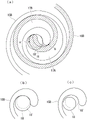
The pair of fixed scroll 15 and orbiting scroll 16 is configured as follows: spiral scrolls 15B and 16B are provided upright on the end plates 15A and 16A, respectively, as wall bodies. The tooth crest 15C of the fixed scroll 15 contacts the tooth bottom surface 16D of the swirling scroll 16, and the tooth crest 16C of the swirling scroll 16 contacts the tooth bottom surface 15D of the fixed scroll 15.
An end plate 16A of the orbiting scroll 16 is provided with: and an end plate side step portion 16E formed such that the height of the end plate side step portion 16E is higher on the center portion side and lower on the outer terminal end side along the vortex of the spiral wrap 16B. Specifically, as shown in fig. 2, an end plate side step portion 16E is provided at a position 180 ° from the position of the end of the spiral wrap 16B of the orbiting scroll 16.
The spiral wrap 15B of the fixed scroll 15 is provided with: and a scroll-side step portion 15E, the scroll-side step portion 15E corresponding to the end plate-side step portion 16E of the above-described orbiting scroll 16, having a height that is lower on the center portion side of the scroll and higher on the outer terminal end side. Specifically, as shown in fig. 2, a scroll-side step portion 15E is provided at a position 360 ° away from the position of the end of the spiral scroll 15B of the fixed scroll 15.
That is, the end plate side step portion 16E is provided only on the end plate 16A of the orbiting scroll 16, and the scroll side step portion 15E is provided only on the scroll-shaped scroll 15B of the fixed scroll 15. Therefore, the spiral wrap 16B of the orbiting scroll 16 is not provided with a stepped portion, and the tips of the spiral wrap 16B are at the same height. The end plate 15A of the fixed scroll 15 is not provided with a stepped portion and is a flat surface.
As shown in fig. 2, the compression chamber 17 is formed by at least a pair of compression chambers 17A and 17B facing each other with the center of the fixed scroll 15 interposed therebetween. In order to distinguish the pair of compression chambers 17A, 17B, in fig. 2, a compression chamber formed on the ventral side (inner circumferential side) of the spiral wrap 15B of the fixed scroll 15 is defined as a ventral compression chamber 17A, and a compression chamber formed on the dorsal side (outer circumferential side) of the spiral wrap 15B of the fixed scroll 15 is defined as a dorsal compression chamber 17B.
In fig. 3, the change in volume of the ventral compression chamber 17A and the dorsal compression chamber 17B is shown. In the figure, the horizontal axis represents the rotation angle θ x, and the vertical axis represents the volume of each compression chamber 17A, 17B.
As can be seen from fig. 3: after the suction and the flow are interrupted at the swirl angle α 1 and a pair of compression chambers are formed on the outermost periphery, the ventral compression chamber 17A and the dorsal compression chamber 17B continue to be compressed at different volumes, and the volume becomes the same at the swirl angle α 2, and the compression is performed up to the swirl angle of discharge. Since the change rate (gradient) of the volume of the abdominal compression chamber 17A is larger than that of the back compression chamber 17B, one of the abdominal compression chambers 17A becomes a higher pressure than the back compression chamber 17B, and the discharge pressure of the abdominal compression chamber 17A may become excessively large.
Therefore, in the present embodiment, as shown in fig. 4(a) and 4(B), the shape of the discharge port 18 is adjusted so that the ventral-side compression chamber 17A communicates with the discharge port 18 before the dorsal-side compression chamber 17B communicates with the ventral-side compression chamber. As a method of adjusting the shape of the discharge port 18, it is sufficient if the discharge port has a diameter larger than the diameter of the discharge port 18' adjusted so that the ventral compression chamber 17A and the dorsal compression chamber 17B are simultaneously opened.
The positions a and b shown in the figure indicate that: the discharge port 18' is set to a communication start position of the pressure-side compression chamber 17A and the back-side compression chamber 17B when the pressure-side compression chamber 17A and the back-side compression chamber 17B are simultaneously opened. From this figure, it can be seen that: if the discharge port 18 has a diameter larger than the diameter of the discharge port 18' adjusted so that the pressure-side compression chamber 17A and the back-side compression chamber 17B are simultaneously opened, the pressure-side compression chamber 17A communicates with the discharge port 18 before the back-side compression chamber 17B.
As shown in fig. 4(c), as another method of adjusting the shape of the discharge port 18, the center position thereof may be moved to the ventral compression chamber 17A side, that is, to the outside (left side in the drawing) of the lap of the spiral lap 15B of the fixed scroll 15, so that the diameter is the same as the diameter of the discharge port 18' adjusted so that the ventral compression chamber 17A and the dorsal compression chamber 17B are simultaneously opened. Alternatively, the discharge port 18 may be formed in an oblong or keyhole shape so as to communicate with the ventral compression chamber 17A first, instead of being formed in a circular shape in cross section.
According to the scroll compressor 1 of the present embodiment, the following operational effects are achieved.
Of the pair of compression chambers 17A, 17B facing each other with the center of the fixed scroll 15 interposed therebetween, the higher pressure ventral compression chamber 17A communicates with the discharge port before the lower pressure dorsal compression chamber 17B.
Thus, even in a configuration in which the end plate 16A of the orbiting scroll 16 is provided with the stepped portion 16E, the spiral wrap 15B of the other fixed scroll 15 is provided with the stepped portion 15E corresponding to the stepped portion 16E, and the pressures of the pair of compression chambers 17A, 17B facing each other across the center of the fixed scroll 15 are different, it is possible to avoid excessive compression of the compression chamber 17A on the ventral side.
Specifically, as shown in fig. 5, the ventral compression chamber 17A communicates with the discharge port 18 at a swirl angle α 3 before a swirl angle α 4 at which the back compression chamber 17B communicates with the discharge port 18, and therefore the ventral compression chamber 17A is not compressed any further after the swirl angle α 3. This can avoid a situation in which energy corresponding to the substantially triangular region a1 shown in fig. 5 becomes a power loss and the compression efficiency is reduced.
In the present embodiment, the description has been made using a configuration in which the end plate side step portion 16E is provided only on the end plate 16A of the orbiting scroll 16 and the scroll side step portion 15E is provided only on the scroll-shaped scroll 15B of the fixed scroll 15, but a configuration opposite to this is also possible.
That is, the present invention can be applied to a configuration in which the end plate side step portion is provided only in the end plate 15A of the fixed scroll 15 and the scroll side step portion is provided only in the spiral scroll 16B of the orbiting scroll 16.
In this case, the configuration is: since the pressure of the back-side compression chamber 17B is higher than that of the abdominal-side compression chamber 17A, the back-side compression chamber 17B communicates with the discharge port 18 before the abdominal-side compression chamber 17A. For example, in fig. 4(a), a notch or a groove is provided on the flank side of the spiral wrap 16B of the orbiting scroll 16 so as to generate a clearance at the position B first.
The present invention is also applicable to a scroll compressor in which end plate side step portions are provided in both end plates of a fixed scroll and a orbiting scroll as described in patent document 1.
That is, when the height of the end plate side step portion provided in the end plate of the orbiting scroll is higher than the height of the end plate side step portion provided in the end plate of the fixed scroll, the pressure in the compression chamber 17A on the ventral side is higher than that in the compression chamber 17B on the back side as in the present embodiment, and therefore, the shape of the discharge port can be adjusted to avoid the over-compression in the compression chamber 17A on the ventral side.
On the other hand, when the height of the end plate side step portion provided in the end plate of the fixed scroll is higher than the height of the end plate side step portion provided in the end plate of the orbiting scroll, the pressure of the back-side compression chamber 17B is higher than that of the front-side compression chamber 17A, and therefore, the front-side of the spiral wrap 16B of the orbiting scroll 16 is provided with the notch or groove, thereby avoiding the excessive compression of the back-side compression chamber 17B.
[ second embodiment ]
Next, a second embodiment of the present invention will be described with reference to fig. 6 to 8.
The present embodiment differs in the following points: the first embodiment further includes a bypass port. Therefore, the same components as those in the first embodiment are denoted by the same reference numerals, and descriptions thereof are omitted.
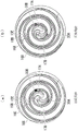
The scroll compressor 1 of the present embodiment has a vertical sectional shape shown in fig. 1. As shown in fig. 6, in the scroll compressor 1 of the present embodiment, bypass ports (extraction ports) 30A and 30B are formed in an end plate 15A of the fixed scroll 15. The bypass ports 30A and 30B are provided with check valves or the like that open when the pressure becomes equal to or higher than a predetermined pressure, and discharge the fluid at or higher than the predetermined pressure before the fluid is discharged from the discharge port 18, thereby preventing excessive compression. In fig. 6, one bypass port 30A corresponds to the ventral compression chamber 17A, and the other bypass port 30B corresponds to the dorsal compression chamber 17B.
In the present embodiment, as shown in fig. 6(a), at the swivel angle β 1, the ventral compression chamber 17A communicates with the bypass port 30A, and the dorsal compression chamber 17B does not communicate with the bypass port 30B. Therefore, at this swirl angle β 1, the fluid of the excess pressure portion is extracted only from the ventral compression chamber 17A. Then, as shown in fig. 6(B), when advancing to the swivel angle β 2, the back-side compression chamber 17B communicates with the bypass port 30B. At this swirl angle β 2, the ventral compression chamber 17A is already in communication with the bypass port 30A.
Fig. 7 shows a communication start timing of the bypass port as a comparative example. In this comparative example, a configuration is adopted in which the pressure difference between the ventral-side compression chamber 17A and the dorsal-side compression chamber 17B is substantially 0 or so small that it does not affect the performance, and as shown in fig. 7(a), the bypass ports 30A, 30B are not communicated with the two compression chambers 17A, 17B at the swivel angle β 1, and as shown in fig. 7(B), the two compression chambers 17A, 17B are simultaneously communicated with the bypass ports 30A, 30B at the swivel angle β 2.
Fig. 8 shows the pressure change caused by the bypass ports 30A and 30B of the present embodiment shown in fig. 6. In the figure, the horizontal axis represents the gyration angle, and the vertical axis represents the pressure. From this figure, it can be seen that: the pressure in the ventral compression chamber 17A is higher than that in the dorsal compression chamber 17B from approximately the turning angle β 0.
Then, as shown in fig. 6(a), the ventral compression chamber 17A starts communicating with the bypass port 30A at the swirl angle β 1, and is not compressed excessively to the required discharge pressure or more. Thereafter, as shown in fig. 6(B), the back-side compression chamber 17B starts communicating with the bypass port 30B at the swirl angle β 2, and is adjusted until the required discharge pressure is reached before the swirl angle β 3 communicating with the discharge port 18.
On the other hand, when both compression chambers 17A, 17B start communicating with the bypass ports 30A, 30B at the same time at the swirl angle β 2 as shown in fig. 7, the compression chamber 17A on the ventral side is compressed excessively to the required discharge pressure or more as shown in fig. 8. Therefore, energy corresponding to the substantially triangular region a2 shown in fig. 8 becomes a power loss, and the compression efficiency is lowered.
According to the scroll compressor 1 of the present embodiment, the following operational effects are achieved.
Of the pair of compression chambers 17A, 17B facing each other with the center of the fixed scroll 15 interposed therebetween, the higher pressure ventral compression chamber 17A communicates with the bypass port 30A earlier than the lower pressure dorsal compression chamber 17B.
Thus, even if the end plate 16A of the orbiting scroll 16 is provided with the stepped portion 16E, and the spiral wrap 15B of the other fixed scroll 15 has a stepped shape 15E corresponding to the stepped portion 16E, and the pressure of the pair of compression chambers 17A and 17B facing each other across the center of the fixed scroll 15 is different, the excessive compression of the compression chamber 17A on the ventral side can be avoided.
In the present embodiment, the end plate side step portion 16E is provided only on the end plate 16A of the orbiting scroll 16, and the scroll side step portion 15E is adopted only on the spiral scroll 15B of the fixed scroll 15.
That is, the present invention can be applied to a configuration in which the end plate side step portion is provided only on the end plate 15A of the fixed scroll 15 and the scroll side step portion is provided only on the spiral scroll 16B of the orbiting scroll 16.
In this case, since the pressure of the back-side compression chamber 17B is higher than that of the abdominal-side compression chamber 17A, the position of the bypass port 30B is adjusted so that the back-side compression chamber 17B communicates with the bypass port 30B before the abdominal-side compression chamber 17A communicates with the abdominal-side compression chamber 17A.
The present invention is also applicable to a scroll compressor in which end plate side step portions are provided in both end plates of a fixed scroll and a orbiting scroll as described in patent document 1.
That is, when the height of the end plate side step portion provided in the end plate of the orbiting scroll is higher than the height of the end plate side step portion provided in the end plate of the fixed scroll, the pressure in the ventral compression chamber 17A is higher than that in the back compression chamber 17B as in the present embodiment, and therefore, the position of the bypass port 30A can be adjusted to avoid the excessive compression in the ventral compression chamber 17A.
On the other hand, when the height of the end plate side step portion provided in the end plate of the fixed scroll is higher than the height of the end plate side step portion provided in the end plate of the orbiting scroll, the pressure of the back-side compression chamber 17B is higher than that of the compression chamber 17A, and therefore, the position of the bypass port 30B can be adjusted to avoid excessive compression of the back-side compression chamber 17B.
Description of the symbols
1 scroll compressor
15 fixed scroll
16-orbiting scroll
15A, 16A end plate
15B, 16B vortex-shaped scroll
15C, 16C tooth crest
15D, 16D tooth bottom surface
15E side step of the scroll (wall side step)
16E end plate side step portion
17 compression chamber
17A ventral compression chamber
17B Back side compression Chamber
30A, 30B bypass port (draw-out port)
Claims (8)
1. A scroll compressor is provided with:
a fixed scroll having a spiral wall body provided upright on one side surface of an end plate;
a swirling disc having swirling wall bodies provided upright on one side surface of an end plate, the wall bodies being supported so as to be capable of revolving and swirling while being prevented from rotating by meshing with each other; and
a discharge port through which the fluid compressed by the two scrolls is discharged,
the one side surface of the end plate of either one of the two scrolls is provided with: an end plate side step portion formed so that a vortex having a height along the wall body is higher on the central portion side thereof and lower on the outer terminal end side thereof,
the other wall of the two scrolls is provided with: a wall-side step portion corresponding to the end-plate-side step portion and formed so as to be lower in height on a central portion side of the vortex and higher on an outer terminal side,
the two scrolls are configured to form a pair of compression chambers,
the convolution angles of the pair of compression chambers at the time of suction cutoff have different volumes from each other,
and the pair of compression chambers have the same volume in the middle of the swirling motion different from the swirl angle at the time of suction flow interruption, wherein the compression chamber having a larger volume at the time of suction flow interruption communicates with the discharge port before the compression chamber having a smaller volume at the time of suction flow interruption.
2. A scroll compressor is provided with:
a fixed scroll having a spiral wall body provided upright on one side surface of an end plate;
a swirling disc having swirling wall bodies provided upright on one side surface of an end plate, the wall bodies being supported so as to be capable of revolving and swirling while being prevented from rotating by meshing with each other;
a discharge port through which the fluid compressed by the two scrolls is discharged; and
a pair of extraction ports provided in an end plate of the fixed scroll with a center of the fixed scroll therebetween,
the one side surface of the end plate of either one of the two scrolls is provided with: an end plate side step portion formed so that a vortex having a height along the wall body is higher on the central portion side thereof and lower on the outer terminal end side thereof,
the other wall of the two scrolls is provided with: a wall-side step portion corresponding to the end-plate-side step portion and formed to have a height lower on a central portion side of the vortex and higher on an outer terminal end side,
the two scrolls are configured to form a pair of compression chambers,
the convolution angles of the pair of compression chambers at the time of suction flow interruption have different volumes from each other,
and the volumes of the swirl angles of the pair of compression chambers in the middle of the swirling motion different from the swirl angle at the time of the suction flow interruption are equal to each other,
of the pair of compression chambers, the compression chamber having the larger volume at the time of suction flow interruption communicates with the suction port before the compression chamber having the smaller volume at the time of suction flow interruption.
3. A scroll compressor is provided with:
a fixed scroll having a spiral wall body provided upright on one side surface of an end plate;
a swirling disc having swirling wall bodies provided upright on one side surface of an end plate, the wall bodies being supported so as to be capable of revolving and swirling while being prevented from rotating by meshing with each other; and
a discharge port through which the fluid compressed by the two scrolls is discharged,
the one side surface of the end plate of either one of the two scrolls is provided with: an end plate side step portion formed so that a vortex having a height along the wall body is higher on the central portion side thereof and lower on the outer terminal end side thereof,
the other wall of the two scrolls is provided with: a wall-side step portion corresponding to the end-plate-side step portion and formed to have a height lower on a central portion side of the vortex and higher on an outer terminal end side,
the two scrolls are configured to form a pair of compression chambers,
the convolution angles of the pair of compression chambers at the time of suction flow interruption have different volumes from each other,
and the pair of compression chambers have the same volume in the middle of the swirling motion and compress the compression chambers to a swirl angle at which the compression chambers discharge,
in the pair of compression chambers, the compression chamber having the larger volume at the time of suction flow interruption communicates with the discharge port before the compression chamber having the smaller volume at the time of suction flow interruption.
4. A scroll compressor is provided with:
a fixed scroll having a spiral wall body provided upright on one side surface of an end plate;
a swirling disc having swirling wall bodies provided upright on one side surface of an end plate, the wall bodies being supported so as to be capable of revolving and swirling while being prevented from rotating by meshing with each other;
a discharge port through which the fluid compressed by the two scrolls is discharged; and
a pair of extraction ports provided in an end plate of the fixed scroll with a center of the fixed scroll therebetween,
the one side surface of the end plate of either one of the two scrolls is provided with: an end plate side step portion formed so that a vortex having a height along the wall body is higher on the central portion side thereof and lower on the outer terminal end side thereof,
the other wall of the two scrolls is provided with: a wall-side step portion corresponding to the end-plate-side step portion and formed to have a height lower on a central portion side of the vortex and higher on an outer terminal end side,
the two scrolls are configured to form a pair of compression chambers,
the convolution angles of the pair of compression chambers at the time of suction flow interruption have different volumes from each other,
and the pair of compression chambers have the same volume in the middle of the swirling motion and compress the compression chambers to a swirl angle at which the compression chambers discharge,
of the pair of compression chambers, the compression chamber having the larger volume at the time of suction flow interruption communicates with the suction port before the compression chamber having the smaller volume at the time of suction flow interruption.
5. A scroll compressor is provided with:
a fixed scroll having a spiral wall body provided upright on one side surface of an end plate;
a swirling disc having swirling wall bodies provided upright on one side surface of an end plate, the wall bodies being supported so as to be capable of revolving and swirling while being prevented from rotating by meshing with each other; and
a discharge port through which the fluid compressed by the two scrolls is discharged,
the side surface of the end plate of the swirling disc is provided with: an end plate side step portion formed so that a vortex having a height along the wall body is higher on the central portion side thereof and lower on the outer terminal end side thereof,
the wall body of the fixed scroll is provided with: a wall-side step portion corresponding to the end-plate-side step portion and formed to have a height lower on a central portion side of the vortex and higher on an outer terminal end side,
the two scrolls are configured to form a pair of compression chambers,
the pair of compression chambers have equal volumes after performing suction and flow interruption and after performing compression to a predetermined swirl angle, wherein,
in the pair of compression chambers, the compression chamber on the one of the front sides of the wall body of the fixed scroll communicates with the discharge port before the compression chamber on the one of the rear sides of the wall body of the fixed scroll.
6. A scroll compressor is provided with:
a fixed scroll having a spiral wall body provided upright on one side surface of an end plate;
a swirling disc having swirling wall bodies provided upright on one side surface of an end plate, the wall bodies being supported so as to be capable of revolving and swirling while being prevented from rotating by meshing with each other;
a discharge port through which the fluid compressed by the two scrolls is discharged; and
a pair of extraction ports provided in an end plate of the fixed scroll with a center of the fixed scroll therebetween,
the side surface of the end plate of the swirling disc is provided with: an end plate side step portion formed so that a vortex having a height along the wall body is higher on the central portion side thereof and lower on the outer terminal end side thereof,
the wall body of the fixed scroll is provided with: a wall-side step portion corresponding to the end-plate-side step portion and formed to have a height lower on a central portion side of the vortex and higher on an outer terminal end side,
the two scrolls are configured to form a pair of compression chambers,
the pair of compression chambers have equal volumes after performing suction and flow interruption and after performing compression to a predetermined swirl angle, wherein,
in the pair of compression chambers, the compression chamber on the one of the front sides of the wall body of the fixed scroll communicates with the discharge port before the compression chamber on the one of the rear sides of the wall body of the fixed scroll.
7. A scroll compressor is provided with:
a fixed scroll having a spiral wall body provided upright on one side surface of the end plate;
a swirling disc having swirling wall bodies provided upright on one side surface of an end plate, the swirling wall bodies being supported so as to be capable of revolving and swirling while being prevented from rotating by meshing the wall bodies with each other; and
a discharge port through which the fluid compressed by the two scrolls is discharged,
the side surface of the end plate of the swirling disc is provided with: an end plate side step portion formed so that a vortex having a height along the wall body is higher on the central portion side thereof and lower on the outer terminal end side thereof,
the wall body of the fixed scroll is provided with: a wall-side step portion corresponding to the end-plate-side step portion and formed to have a height lower on a central portion side of the vortex and higher on an outer terminal end side,
the two scrolls are configured to form a pair of compression chambers, wherein,
the discharge port has a diameter equal to a diameter of a discharge port adjusted so that a ventral compression chamber on a ventral side of the wall body of the fixed scroll and a dorsal compression chamber on a dorsal side of the wall body of the fixed scroll of the pair of compression chambers are simultaneously opened, and the discharge port is provided so that a center position thereof moves to the ventral compression chamber side or moves to an outer side of a ring of the wall body of the fixed scroll.
8. The scroll compressor according to any one of claims 1 to 7, wherein,
the end plate side step portion is located in the vicinity of a position 180 ° away from a position of a vortex tail of a wall body of the scroll on which the end plate side step portion is provided.
Applications Claiming Priority (4)
| Application Number | Priority Date | Filing Date | Title |
|---|---|---|---|
| JP2015-053693 | 2015-03-17 | ||
| JP2015053693A JP6685649B2 (en) | 2015-03-17 | 2015-03-17 | Scroll compressor |
| PCT/JP2016/058314 WO2016148187A1 (en) | 2015-03-17 | 2016-03-16 | Scroll compressor |
| CN201680015351.7A CN107429692B (en) | 2015-03-17 | 2016-03-16 | Scroll compressor having a discharge port |
Related Parent Applications (1)
| Application Number | Title | Priority Date | Filing Date |
|---|---|---|---|
| CN201680015351.7A Division CN107429692B (en) | 2015-03-17 | 2016-03-16 | Scroll compressor having a discharge port |
Publications (2)
| Publication Number | Publication Date |
|---|---|
| CN111894852A CN111894852A (en) | 2020-11-06 |
| CN111894852B true CN111894852B (en) | 2022-07-05 |
Family
ID=56920034
Family Applications (2)
| Application Number | Title | Priority Date | Filing Date |
|---|---|---|---|
| CN201680015351.7A Active CN107429692B (en) | 2015-03-17 | 2016-03-16 | Scroll compressor having a discharge port |
| CN202010811103.1A Active CN111894852B (en) | 2015-03-17 | 2016-03-16 | Scroll compressor having a scroll compressor with a suction chamber |
Family Applications Before (1)
| Application Number | Title | Priority Date | Filing Date |
|---|---|---|---|
| CN201680015351.7A Active CN107429692B (en) | 2015-03-17 | 2016-03-16 | Scroll compressor having a discharge port |
Country Status (5)
| Country | Link |
|---|---|
| US (2) | US11326602B2 (en) |
| JP (1) | JP6685649B2 (en) |
| CN (2) | CN107429692B (en) |
| DE (1) | DE112016001228T5 (en) |
| WO (1) | WO2016148187A1 (en) |
Families Citing this family (1)
| Publication number | Priority date | Publication date | Assignee | Title |
|---|---|---|---|---|
| JP6685649B2 (en) * | 2015-03-17 | 2020-04-22 | 三菱重工サーマルシステムズ株式会社 | Scroll compressor |
Citations (5)
| Publication number | Priority date | Publication date | Assignee | Title |
|---|---|---|---|---|
| JP2002195174A (en) * | 2000-12-25 | 2002-07-10 | Hitachi Ltd | Scroll fluid machine |
| CN1201083C (en) * | 2000-06-22 | 2005-05-11 | 三菱重工业株式会社 | Scrawl compressor |
| JP2008095637A (en) * | 2006-10-13 | 2008-04-24 | Mitsubishi Heavy Ind Ltd | Scroll compressor |
| CN100453813C (en) * | 2004-12-23 | 2009-01-21 | Lg电子株式会社 | Apparatus for varying capacity in scroll compressor |
| CN104005953A (en) * | 2013-02-21 | 2014-08-27 | 日立空调·家用电器株式会社 | Scroll compressor |
Family Cites Families (16)
| Publication number | Priority date | Publication date | Assignee | Title |
|---|---|---|---|---|
| JPS6017956B2 (en) | 1981-08-18 | 1985-05-08 | サンデン株式会社 | Scroll compressor |
| JPS6037320B2 (en) * | 1981-10-12 | 1985-08-26 | サンデン株式会社 | Scroll compressor |
| US4477238A (en) * | 1983-02-23 | 1984-10-16 | Sanden Corporation | Scroll type compressor with wrap portions of different axial heights |
| JPH04121483A (en) | 1990-09-12 | 1992-04-22 | Toshiba Corp | Scroll type compressor |
| JPH04255589A (en) | 1991-02-08 | 1992-09-10 | Toshiba Corp | Scroll type compressor |
| JP3543367B2 (en) | 1994-07-01 | 2004-07-14 | ダイキン工業株式会社 | Scroll compressor |
| JP4301714B2 (en) | 2000-08-28 | 2009-07-22 | 三菱重工業株式会社 | Scroll compressor |
| JP4410392B2 (en) | 2000-06-22 | 2010-02-03 | 三菱重工業株式会社 | Scroll compressor |
| JP4709439B2 (en) * | 2001-07-24 | 2011-06-22 | 三菱重工業株式会社 | Scroll compressor |
| CN100371598C (en) * | 2003-08-11 | 2008-02-27 | 三菱重工业株式会社 | Scroll compressor |
| JP2008267150A (en) * | 2007-04-16 | 2008-11-06 | Sanden Corp | Fluid machine |
| JP5342137B2 (en) * | 2007-12-27 | 2013-11-13 | 三菱重工業株式会社 | Scroll compressor |
| JP5393063B2 (en) * | 2008-06-10 | 2014-01-22 | 三菱重工業株式会社 | Scroll compressor |
| JP2014145324A (en) | 2013-01-30 | 2014-08-14 | Hitachi Appliances Inc | Scroll compressor |
| JP6352109B2 (en) * | 2014-08-22 | 2018-07-04 | 三菱重工業株式会社 | Horizontal stepped scroll compressor |
| JP6685649B2 (en) * | 2015-03-17 | 2020-04-22 | 三菱重工サーマルシステムズ株式会社 | Scroll compressor |
-
2015
- 2015-03-17 JP JP2015053693A patent/JP6685649B2/en active Active
-
2016
- 2016-03-16 WO PCT/JP2016/058314 patent/WO2016148187A1/en active Application Filing
- 2016-03-16 CN CN201680015351.7A patent/CN107429692B/en active Active
- 2016-03-16 DE DE112016001228.4T patent/DE112016001228T5/en active Pending
- 2016-03-16 CN CN202010811103.1A patent/CN111894852B/en active Active
- 2016-03-16 US US15/551,621 patent/US11326602B2/en active Active
-
2022
- 2022-03-31 US US17/710,378 patent/US20220220960A1/en active Pending
Patent Citations (5)
| Publication number | Priority date | Publication date | Assignee | Title |
|---|---|---|---|---|
| CN1201083C (en) * | 2000-06-22 | 2005-05-11 | 三菱重工业株式会社 | Scrawl compressor |
| JP2002195174A (en) * | 2000-12-25 | 2002-07-10 | Hitachi Ltd | Scroll fluid machine |
| CN100453813C (en) * | 2004-12-23 | 2009-01-21 | Lg电子株式会社 | Apparatus for varying capacity in scroll compressor |
| JP2008095637A (en) * | 2006-10-13 | 2008-04-24 | Mitsubishi Heavy Ind Ltd | Scroll compressor |
| CN104005953A (en) * | 2013-02-21 | 2014-08-27 | 日立空调·家用电器株式会社 | Scroll compressor |
Also Published As
| Publication number | Publication date |
|---|---|
| JP6685649B2 (en) | 2020-04-22 |
| WO2016148187A1 (en) | 2016-09-22 |
| CN107429692A (en) | 2017-12-01 |
| DE112016001228T5 (en) | 2017-12-21 |
| CN107429692B (en) | 2020-09-11 |
| US11326602B2 (en) | 2022-05-10 |
| US20180038367A1 (en) | 2018-02-08 |
| CN111894852A (en) | 2020-11-06 |
| JP2016173069A (en) | 2016-09-29 |
| US20220220960A1 (en) | 2022-07-14 |
Similar Documents
| Publication | Publication Date | Title |
|---|---|---|
| JP6180860B2 (en) | Scroll compressor | |
| US9267501B2 (en) | Compressor including biasing passage located relative to bypass porting | |
| JP4310960B2 (en) | Scroll type fluid machinery | |
| EP2581605B1 (en) | Scroll compressor with bypass hole | |
| CN111894852B (en) | Scroll compressor having a scroll compressor with a suction chamber | |
| JP6906887B2 (en) | Scroll fluid machine | |
| CN107429690B (en) | Scroll fluid machine having a plurality of scroll members | |
| JP2016169661A (en) | Scroll compressor | |
| EP3683445B1 (en) | Screw compressor | |
| EP3751143B1 (en) | Scroll fluid machine | |
| JP6932797B2 (en) | Scroll compressor | |
| WO2019163628A1 (en) | Scroll fluid machine | |
| JP4131561B2 (en) | Scroll compressor | |
| EP4293229A1 (en) | Scroll compressor | |
| JP6008516B2 (en) | Scroll compressor | |
| JP7023739B2 (en) | Scroll fluid machine | |
| WO2019163536A1 (en) | Scroll fluid machine | |
| WO2020059608A1 (en) | Multiple-stage compressor | |
| EP2053247A1 (en) | Multistage compressor | |
| JP5550425B2 (en) | Scroll compressor | |
| JP2002070765A (en) | Preventive mechanism of excessive compression in scroll compressor |
Legal Events
| Date | Code | Title | Description |
|---|---|---|---|
| PB01 | Publication | ||
| PB01 | Publication | ||
| SE01 | Entry into force of request for substantive examination | ||
| SE01 | Entry into force of request for substantive examination | ||
| GR01 | Patent grant | ||
| GR01 | Patent grant |