CN111894307A - Fully-assembled standardized temporary support structure and construction method - Google Patents
Fully-assembled standardized temporary support structure and construction method Download PDFInfo
- Publication number
- CN111894307A CN111894307A CN202010769408.0A CN202010769408A CN111894307A CN 111894307 A CN111894307 A CN 111894307A CN 202010769408 A CN202010769408 A CN 202010769408A CN 111894307 A CN111894307 A CN 111894307A
- Authority
- CN
- China
- Prior art keywords
- bailey
- tower crane
- frame
- frames
- crane standard
- Prior art date
- Legal status (The legal status is an assumption and is not a legal conclusion. Google has not performed a legal analysis and makes no representation as to the accuracy of the status listed.)
- Pending
Links
Images


Classifications
-
- E—FIXED CONSTRUCTIONS
- E04—BUILDING
- E04G—SCAFFOLDING; FORMS; SHUTTERING; BUILDING IMPLEMENTS OR AIDS, OR THEIR USE; HANDLING BUILDING MATERIALS ON THE SITE; REPAIRING, BREAKING-UP OR OTHER WORK ON EXISTING BUILDINGS
- E04G25/00—Shores or struts; Chocks
- E04G25/02—Shores or struts; Chocks non-telescopic
-
- E—FIXED CONSTRUCTIONS
- E04—BUILDING
- E04G—SCAFFOLDING; FORMS; SHUTTERING; BUILDING IMPLEMENTS OR AIDS, OR THEIR USE; HANDLING BUILDING MATERIALS ON THE SITE; REPAIRING, BREAKING-UP OR OTHER WORK ON EXISTING BUILDINGS
- E04G21/00—Preparing, conveying, or working-up building materials or building elements in situ; Other devices or measures for constructional work
Abstract
The invention discloses a fully-assembled standardized temporary support structure and a construction method, and belongs to the field of construction equipment. The main structure of the standardized temporary supporting structure comprises a bottom connecting structure, a tower crane standard knot, a connecting Bailey frame and a top supporting frame. Bottom connection structure has a plurality ofly, and homodisperse arranges in interim bearing structure's installation place. And a support column is formed on each bottom connecting structure by installing a plurality of vertically assembled tower crane standard joints. The support columns are connected into a whole through the connecting Bailey frames, and the two ends of the connecting Bailey frames and the support columns are fixedly connected through fully-assembled connecting nodes. And a plurality of top supporting frames are erected at the tops of all the supporting columns and are used for supporting the space structure to be constructed. This interim bearing structure adopts tower crane standard festival, bailey frame etc. that mainly adopt to be standardized component, can increase the utilization ratio in bottom space. The whole supporting system is assembled, so that field welding work can be avoided, and the installation and turnover are convenient.
Description
Technical Field
The invention belongs to the field of construction equipment, and particularly relates to a fully-assembled standardized temporary support structure and a construction method.
Background
In the construction process of a space structure, a support frame is often required to be erected, and a common support frame consists of a scaffold or a section steel column. If the scaffold is adopted, the building area is large, other operations cannot be performed below the scaffold, and when the supporting height is large, the stability of the scaffold is insufficient; if the section steel column is adopted, the installation process is troublesome, a lot of welding work is needed, and the section steel column is difficult to turnover.
The tower crane standard knot is adopted as temporary support in the construction of part space structure engineering at present, and when the support height is great, the stability of support system is not enough, need add the off-plane support, and general method can only be connected with the support again at tower crane standard knot welded component, but the welding can damage the tower crane standard knot, influences the turnover and uses to welding cost time and labour cost are more.
Therefore, it is desirable to provide a temporary support system with an assembly type to avoid welding work on site and facilitate installation and turnover.
Disclosure of Invention
The invention aims to solve the problems in the prior art and provides a fully-assembled standardized temporary support structure and a construction method.
The invention adopts the following specific technical scheme:
a fully-assembled standardized temporary supporting structure comprises a bottom connecting structure, a tower crane standard knot, a connecting Bailey truss and a top supporting frame;
the plurality of bottom connecting structures are dispersedly arranged in the installation site of the temporary supporting structure; each bottom connecting structure is provided with a plurality of vertically assembled tower crane standard joints to form a supporting column; the support columns are connected into a whole through the connecting Bailey frames, and the two ends of the connecting Bailey frames are fixedly connected with the support columns through fully-assembled connecting nodes; and a plurality of top supporting frames are erected at the tops of all the supporting columns and are used for supporting the space structure to be constructed.
Preferably, each bottom connecting structure comprises a plurality of first distribution beams; the first distribution beams are made of H-shaped steel, and the first distribution beams are horizontally and longitudinally spliced in a mode that flange plates are horizontally arranged to form a base; the base is provided with a plurality of first holes on an upper flange plate of the H-shaped steel, two sides below each first hole are respectively provided with a stiffening rib, the two stiffening ribs are supported between the upper flange plate and a lower flange plate of the H-shaped steel, and a horizontal first connecting plate is fixed between the two stiffening ribs; the first connecting plate is provided with a second opening superposed with the projection of the first opening on the horizontal plane; the first opening and the second opening which are superposed in each pair of projections are communicated through a vertical first connecting sleeve and used for inserting a first connecting pin for connecting an external tower crane standard knot; the base is provided with a plurality of second connecting plates, the second connecting plates are provided with third holes, and anchor bolts are installed in the third holes and used for fixing the bottom connecting structure to the ground.
Preferably, the fully-assembled connecting joint comprises a plurality of bent steel plates and connecting bolts; each bent steel plate is bent into a multi-section structure and is divided into a main body section and connecting sections positioned at two ends of the main body section; the bending steel plates can be sequentially connected end to form a node frame, main body sections of all the bending steel plates in the node frame enclose an annular area, and connecting sections at the end parts of two adjacent bending steel plates are butted and spliced and are fixed in a penetrating mode through connecting bolts; the cross section of the annular area can completely wrap the cross section of the upright post of the tower crane standard knot fixed by the connecting node; the node frame passes through the annular region tightly overlaps fixedly on the stand of tower crane standard festival, connect the bailey truss tip with thereby the stand is erect to connecting bolt connection is fixed.
Furthermore, the number of internal corners in the cross section of the annular region is the same as the number of external corners in the cross section of the upright post, and the internal corners of the annular region and the external corners of the upright post are correspondingly clamped in a one-to-one mode in a fastening state.
Furthermore, in all the bent steel plates of the node frame, the connecting sections of any two adjacent bent steel plates are located on the periphery of the annular area.
Furthermore, one or more bailey frames are fixed on one node frame.
Furthermore, in the node frame, when the connecting sections of at least two adjacent bent steel plate end parts are in butt joint and spliced, a distance is kept between the connecting sections and the upright columns, and the distance is used for adjusting pressing force between the node frame and the upright columns.
Preferably, the top support frame comprises a top bailey frame, second distribution beams and distribution beam connecting assemblies, the top bailey frame is horizontally erected on the tops of at least two support columns, a plurality of second distribution beams are arranged on the top of the top bailey frame, each second distribution beam is fixed on the top bailey frame through one group of distribution beam connecting assemblies, each group of distribution beam connecting assemblies comprises a U-shaped connecting piece and a connecting steel plate, the arc inner bottom of each U-shaped connecting piece is clamped on at least one rod piece of the top bailey frame, the second distribution beams are located in openings in the tops of the U-shaped connecting pieces, and the connecting steel plates are attached to the top surfaces of the second distribution beams and are fixedly connected with two sides of the openings of the U-shaped connecting.
Furthermore, the top of the opening of the U-shaped connecting piece is higher than the top surface of the second distribution beam, and the U-shaped connecting piece is used for allowing a rod piece of the space structure to penetrate through the opening and horizontally limiting the space structure.
Preferably, a height adjusting component is arranged between the top of the supporting column and the top supporting frame.
Another object of the present invention is to provide a method for constructing a temporary space structure by a standardized temporary support structure according to any one of the above aspects, comprising the steps of:
s1: leveling, measuring and lofting an installation site of the temporary support structure, and marking the position of a concrete foundation on the ground;
s2: arranging a concrete platform at each marked concrete foundation position, embedding a plurality of anchor bolts in the concrete platforms, wherein the embedding positions of the anchor bolts correspond to the third open holes on the second connecting plate in the bottom connecting structure one by one;
s3: installing one bottom connecting structure on each concrete platform, and connecting and fixing the bottom connecting structures and anchor bolts pre-embedded in the concrete platforms one by one to enable the bottom connecting structures and the concrete platforms to be connected into a whole;
s4: tower crane standard knots are sequentially installed on each bottom connecting structure to form a supporting column, the bottommost tower crane standard knot and the bottom connecting structure are fixed through a first connecting pin, and the rest tower crane standard knots are connected in an assembling mode through second connecting pins;
s5: hoisting the connecting bailey frames to a designed height, wherein two ends of each connecting bailey frame are respectively fixed on the tower crane standard knot of the support column through the fully-assembled connecting nodes; all the support columns are connected through a plurality of connecting bailey frames to form an integral stress structure;
s6: hoisting a height adjusting component on the top of the support column of which the top does not reach the designed height so as to meet the requirement of the designed height;
s7: hoisting a plurality of top bailey frames to the tops of the support columns respectively, and fixing the frames on different support columns according to the design direction;
s8: and installing second distribution beams on the top Bailey frames according to design requirements, and relatively fixing each second distribution beam on the top Bailey frames through a U-shaped connecting piece and a connecting steel plate to finish the construction of temporary support of the space structure.
Compared with the prior art, the invention has the following beneficial effects:
1. the temporary support structure adopts fully standardized components, and the bailey frames and the tower crane standard knots are very mature standard parts in the market, can be directly leased and used, and are convenient to turnover.
2. The temporary support structure is installed in a fully-assembled mode, no welding work is performed on the site, and no damage is caused to the Bailey frames and the tower crane standard knots.
3. The temporary supporting structure can be automatically adjusted and combined according to needs, is suitable for construction of any space structure, and can be repeatedly used.
4. In the temporary supporting structure, the height of the top structure can be adjusted through the components erected on the rectangular pipes so as to meet the requirements of different engineering constructions.
5. In the temporary supporting structure, the top is supported and loaded by the bailey frames, and the distributing beams are supported at the key nodes, so that the bearing capacity and stability of the supporting system are improved.
6. In the temporary supporting structure, the Bailey truss is used for providing out-of-plane support for the standard section of the tower crane, and the stability of the whole temporary supporting system is improved, so that the whole supporting system can be set to a higher height according to construction requirements, and the supporting requirement of an ultrahigh space structure is met.
Drawings
FIG. 1 is a schematic supporting diagram of a fully assembled standardized temporary support structure for a space structure from a front view;
FIG. 2 is a schematic supporting view of a fully assembled standardized temporary support structure to a space structure under an axial view;
FIG. 3 is a schematic structural view of a fully assembled standardized temporary support structure;
FIG. 4 is a schematic connection diagram of a bottom connection structure and a tower crane standard knot;
FIG. 5 is a schematic view of a bottom attachment structure;
FIG. 6 is an installation schematic diagram of a bottom connection structure and a first tower crane standard knot;
FIG. 7 is a schematic diagram of a tower crane standard knot connection position;
FIG. 8 is a schematic diagram of a fully assembled connection node structure;
FIG. 9 is a schematic view of a connection node installation connection;
FIG. 10 is a schematic view of another fully assembled connection node configuration;
FIG. 11 is a schematic view of the connection of the connecting bailey frames, top support frames, space structures on a single support column with height adjustment members;
FIG. 12 is a schematic view of the connection of the support post to the top support shelf without the height adjustment member;
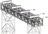
FIG. 13 is a schematic structural view of the top support frame;
FIG. 14 is an enlarged schematic view of the top support stand;
FIG. 15 is a schematic plan view of a plurality of top support stands;
FIG. 16 is a schematic plan view of the spatial structure as mounted on the top support;
fig. 17 is an enlarged view of the position of the top of the spatial structure on the top support frame.
The reference numbers in the figures are: the tower crane comprises a bottom connecting structure 1, a tower crane standard knot 2, a connecting bailey truss 3, a top supporting frame 4, a space structure 5, a height adjusting member 6, a first distribution beam 101, a stiffening rib 102, a second connecting plate 103, an anchor bolt 104, a first connecting plate 105, a first connecting sleeve 106, a first connecting pin 107, a second connecting sleeve 201, a second connecting pin 202, a first bent steel plate 301, a second bent steel plate 302, a third bent steel plate 303, a first connecting bolt 304, a second connecting bolt 305, a third connecting bolt 306, a top bailey truss 401, a second distribution beam 402, a U-shaped connecting piece 403 and a connecting steel plate 404.
Detailed Description
The invention will be further elucidated and described with reference to the drawings and the detailed description. The technical features of the embodiments of the present invention can be combined correspondingly without mutual conflict.
In a preferred embodiment of the invention, as shown in figures 1 and 2, a fully assembled standardized temporary support structure is provided for temporarily supporting the space structure 5.
As shown in fig. 3, the main structure of the standardized temporary support structure comprises a bottom connecting structure 1, a tower crane standard knot 2, a connecting bailey truss 3 and a top support frame 4. The bottom connection structure 1 is provided with a plurality of bottom connection structures which are uniformly distributed in the installation site of the temporary support structure. And a support column is formed on each bottom connecting structure 1 by installing a plurality of vertically assembled tower crane standard sections 2. All the supporting columns are connected into a whole through the connecting bailey frames 3, and the two ends of each connecting bailey frame 3 and the supporting columns are fixedly connected through fully-assembled connecting nodes. And a plurality of top support frames 4 are erected at the tops of all the support columns and used for supporting a space structure 5 to be constructed. This interim bearing structure adopts tower crane standard festival, bailey frame etc. that mainly adopt to be standardized component, and stability is good, can increase the utilization ratio in bottom space. Meanwhile, the whole supporting system is assembled, so that field welding work can be avoided, and the installation and turnover are convenient.
Specific implementation forms of the structures of the parts are described in detail below for easy understanding.
As shown in fig. 4, the bottom connecting structure 1 includes a first distribution beam 101, a stiffener 102, a second connecting plate 103, an anchor 104, a first connecting plate 105, a first connecting sleeve 106, and the like. The first distribution beam 101 is made of H-shaped steel, a plurality of first distribution beams 101 are spliced transversely and longitudinally to form a base, flange plates of the first distribution beams 101 need to be horizontally arranged when the first distribution beams are spliced, and webs need to be vertically arranged. In this embodiment, the first distribution beam 101 is assembled into a base in two horizontal and two vertical directions.
Be equipped with a plurality of first trompils on the base, these first trompils need be seted up on the upper limb listrium of H shaped steel, and its effect is used for carrying out the pin joint with tower crane standard festival 2 of treating the installation. Because the external tower crane standard knot 2 props up in the position of these first trompils, therefore here need carry out structural reinforcement to H shaped steel. Referring to fig. 5 and 6, a stiffening rib 102 is respectively disposed at both sides below each first opening, both stiffening ribs 102 are supported between the upper flange plate and the lower flange plate of the H-section, and a horizontal first connecting plate 105 is fixed between the two stiffening ribs 102. In this embodiment, the stiffening ribs 102 and the first connecting plate 105 are made of steel plates, the stiffening ribs 102 are welded and fixed between the upper flange plate, the lower flange plate and the web plate of the H-shaped steel, and two ends of the first connecting plate 105 are welded and fixed with the left stiffening rib 102 and the right stiffening rib 102.
The first connecting plate 105 is used for providing a supporting point of the first connecting pin 107 used in installation of the external tower crane standard knot 2, so that the first connecting plate 105 is required to be provided with a second opening, and the projection of the second opening and the projection of the first opening on the horizontal plane should be overlapped so as to ensure that the first connecting pin 107 can pass through the second opening and the first opening. In addition, in order to facilitate the first connecting pin 107 to pass through the second opening and the first opening, a first connecting sleeve 106 may be disposed between each pair of the first opening and the second opening with the projection coinciding with each other, and two ends of the first connecting sleeve 106 are respectively communicated with the first opening and the second opening. Therefore, one end of the first connecting pin 107 is connected to the external tower crane standard knot 2, and the other end of the first connecting pin can sequentially pass through the first opening, the first connecting sleeve 106 and the second opening, and then is fastened and fixed on the first connecting plate 105 through a nut. A plurality of loci in 2 bottoms of whole tower crane standard festival all pass through first connecting pin 107 and first distribution roof beam 101 fixed back, can accomplish its integral erection fixed.
The number of the first holes in the base is adjusted according to actual conditions, and the number of the connecting points on the tower crane standard knot 2 is used as the standard. A second connecting sleeve 201 is fixed at four corners of the general tower crane standard knot 2, the second connecting sleeves 201 at the four corners of the two tower crane standard knots 2 are aligned when the two tower crane standard knots are assembled, and then a second connecting pin 202 is inserted for connection and fixation, as shown in fig. 7. Therefore, also be equipped with four first trompils on the base in four corners angular point position altogether on this embodiment, four first trompils positions on the base and wait to connect the tower crane standard festival 2 go up fixed second adapter sleeve 201 one-to-one. When the installation, aim at four first trompils on the base respectively with four second adapter sleeve 201 of tower crane standard festival 2 four corners, then penetrate first connecting pin 107 respectively and accomplish fixedly.
In addition, the base of the connection structure is horizontally placed on the ground, but the connection structure still needs to be connected and fixed with the ground, so that the base is provided with a plurality of second connection plates 103. In this embodiment, the second connecting plate 103 is also made of a steel plate, and the second connecting plate 103 may be directly welded and fixed to the lower flange plate of the H-shaped steel. The second connecting plate 103 is provided with a third opening, in which an anchor bolt 104 is installed, and the anchor bolt 104 can be driven into a concrete foundation which is cast in advance on the ground, for fixing the bottom connecting structure 1 to the ground. The anchor 104 may be a pre-buried anchor or a chemical anchor. The number of the second connecting plates 103 can be adjusted according to the overall stress condition, and the second connecting plates are uniformly distributed on the bottom plane of the whole base as much as possible.
From this, can erect many support columns in the construction site through assembling tower crane standard festival 2, in order to improve the wholeness between these support columns, improve the antidumping ability, need connect each support column through connecting 3 of bailey frame. The field weld need be carried out in being connected between conventional bailey frame and the support column, but the welding itself is consuming time longer, and the construction is loaded down with trivial details, can lead to the fact the influence to bailey frame and tower crane standard festival structure itself moreover, consequently in this embodiment, provides a tower crane standard festival 2 and the full assembled connected node who is connected bailey frame 3, and full assembled connected node can have multiple different structures, but its basic form is the same, and the essential element includes a plurality of steel sheets of buckling and connecting bolt. Wherein, each bent steel plate is bent into a multi-section structure and is divided into a main body section and connecting sections positioned at two ends of the main body section. The plurality of bent steel plates can be sequentially connected end to form a node frame, main body sections of all the bent steel plates in the node frame are enclosed to form an annular area, and it is noted that the annular area is not necessarily an completely closed ring, and partial openings and gaps can exist in the annular area. The connecting sections at the end parts of the two adjacent bent steel plates are in butt joint and are fixed through the connecting bolts after being in butt joint and splicing. The annular area is used for being sleeved on the upright post of the tower crane standard knot fixed on the connecting node, so that the cross section of the annular area can completely wrap the cross section of the upright post. In addition, because the node frame and the upright post cannot be completely matched, when at least two adjacent bent steel plates in the node frame are in butt joint at the connecting sections of the end parts, the connecting sections of the two adjacent bent steel plates keep a distance for adjusting the pressing force between the node frame and the upright post. The size of the annular area can be properly adjusted through the tightness of the connecting bolts so as to ensure that proper pressing force is provided between the node frame and the upright post. Therefore, in the assembly type connecting node, the node frame is tightly sleeved on the upright post of the tower crane standard node through the annular area and fixed, and the end part of the connecting bailey truss 3 is fixedly connected with the connecting bolt so as to be erected on the upright post. In order to ensure the fit tightness of the annular region and the upright post, the number of the internal corners in the cross section of the annular region is preferably the same as that of the external corners in the cross section of the upright post, and the internal corners of the annular region and the external corners of the upright post are correspondingly clamped one by one in a fastening and fixing state so as to increase the contact area as much as possible.
In addition, in order to ensure the convenience of installation, in all the bent steel plates of the node frame, the connecting sections of any two adjacent bent steel plates are positioned on the periphery of the annular area, namely the connecting sections cannot stretch into the annular area, so that the difficulty in installing the stand column is avoided. In order to ensure the structural strength, the connecting bolt should be a high-strength bolt.
The shape of the annular area of the node frame in the fully-assembled connecting node is required to be adjusted according to the cross section shape of the upright column on the tower crane standard node 2. In this embodiment, the column on the tower crane standard knot 2 is rectangular, so a fully assembled connection node suitable for a rectangular pipe column is adopted here, and the fully assembled connection node comprises a first bent steel plate 101, a second bent steel plate 102, a third bent steel plate 103, a first connection bolt 104, a second connection bolt 105 and a third connection bolt 106. As shown in fig. 8, the first bending steel plate 101, the second bending steel plate 102, and the third bending steel plate 103 are all bent into a multi-section structure by using a strip-shaped steel plate, and are divided into a main section and connecting sections located at two ends of the main section, which are spliced end to form a node frame. The annular area of the node frame is rectangular, and is provided with four internal corners corresponding to four external corners of the rectangular pipe. The third connecting bolt 106 connects one end of the first bent steel plate 101 and one end of the third bent steel plate 103, the connecting sections at the ends of the first bent steel plate and the third bent steel plate are pressed against each other, and the third connecting bolt 106 is fixed by a nut after penetrating through the connecting sections. The bent steel plate connecting sections connected by the first connecting bolts 104 and the second connecting bolts 105 are not attached, and a certain distance is kept, so that the size of the annular area is changed by adjusting the tightness of the connecting bolts, and the pressing force between the node frame and the upright column is adjusted. The connecting section of the first bent steel plate 101 and the connecting section of the second bent steel plate 102 keep a small distance, and the two ends of the first connecting bolt 104 extend out of the connecting sections for a long distance, so that the end part of the bailey truss can be hung on the section between the end part of the first connecting bolt 104 and the connecting sections. The connecting section of the second bending steel plate 102 and the connecting section of the third bending steel plate 103 are spaced at a larger distance, two ends of the second connecting bolt 105 are fixed on the connecting sections at two sides through nuts, and a larger space is reserved between the connecting sections at two sides for the end part of the bailey truss to extend into.
The installation form of this assembled connected node is shown in fig. 9, and the node frame passes through the annular region and tightly overlaps on the stand 2 of tower crane standard festival fixedly, thereby connects 3 tip of bailey frame and connecting bolt and be connected fixedly and erect on the stand. As mentioned before, the connection node may provide two different forms of connection of the ends of the bailey truss 3.
Of course, in the above embodiment, one connecting bailey frame 3 may be fixed to one node frame, or a plurality of connecting bailey frames 3 may be fixed to the node frame at the same time, and the fixing may be specifically adjusted as needed. For example, the node frame shown in fig. 8 may be simplified, and only one connecting bailey frame 3 is fixed, and the structure in this case is composed of only two bent steel plates, as shown in fig. 10. The peripheral part connecting bailey frames 3 may take the form of the connecting node shown in fig. 10, and the middle part connecting bailey frames 3 may take the form of the connecting node shown in fig. 8.
After all the support columns have been assembled and connected, a space structure 5 for supporting the structure to be constructed can be installed on top of them. Because the support column is assembled by tower crane standard festival 2, and tower crane standard festival 2 is the standard component, and its height is fixed, but spatial structure 5 is different to the height requirement of support column in different positions. Therefore, there may be a situation where the height of the support column assembled by the tower crane standard knot 2 cannot meet the requirement, and at this time, a height adjusting member 6 needs to be arranged between the top of the support column and the top support frame 4, as shown in fig. 11. The height adjusting member 6 can be formed by erecting rectangular pipes, and the height of the top structure can be adjusted by the height adjusting member to meet the requirements of different engineering constructions. Of course, if the supporting column itself assembled by the tower crane standard knot 2 can meet the height requirement, the height adjusting member 6 is not needed to be arranged, as shown in fig. 12.
As shown in fig. 13, the top support frame 4 in this embodiment includes a top beret 401, a second distribution beam 402 and a distribution beam connection assembly, wherein two ends of the top beret 401 are horizontally erected on top of two support columns, and an additional support column may be disposed in the middle when the top beret 401 spans too large. Since the space structure 5 in this embodiment is composed of a plurality of rods, in order to facilitate uniform force transmission, a plurality of second distribution beams 402 need to be arranged on the top of the top bailey truss 401 for uniform force distribution. Each second distribution beam 402 is fixed to the top bailey frame 401 by a set of distribution beam connection assemblies. Referring to fig. 14, each group of distribution beam connection assemblies comprises a U-shaped connection member 403 and a connection steel plate 404, the U-shaped connection member 403 is sleeved on one rod of the top bailey truss 401, the arc-shaped inner bottom of the U-shaped connection member is clamped on at least one rod of the top bailey truss 401, and the second distribution beam 402 is positioned in an opening at the top of the U-shaped connection member 403. Then, a connecting steel plate 404 with two through holes is attached to the top surface of the second distribution beam 402 and fixed to the two sides of the opening of the U-shaped connecting member 403. The connecting steel plate 404 and the U-shaped connecting member 403 may be fixed by a nut or other fasteners.
As shown in fig. 15 and 16, the entire space structure 5 can be supported integrally on the second distribution beams 402 of each top beret 401, for temporary support thereof. In addition, as shown in fig. 17, the open top of the U-shaped connecting member 403 is preferably higher than the top surface of the second distribution beam 402 for the rods of the space structure 5 to pass through for horizontally limiting the space structure 5.
Based on the standardized temporary support structure, the invention further provides a temporary support construction method for the spatial structure, which comprises the following steps:
s1: leveling and measuring lofting are carried out on the installation site of the temporary supporting structure, and the position of the concrete foundation is marked on the ground.
S2: and arranging a concrete platform at each marked concrete foundation position, embedding a plurality of anchor bolts 104 in the concrete platform, wherein the embedded positions of the anchor bolts 104 correspond to the third open holes on the second connecting plate 103 in the bottom connecting structure 1 one by one. The concrete platform can be cast in place, a precast concrete bottom plate can also be adopted, the whole foundation is precast in a factory, and only needs to be hoisted in place on site. The anchor 104 may be a pre-buried anchor or a chemical anchor.
S3: a bottom connecting structure 1 is installed on each concrete platform, and the bottom connecting structures 1 and anchor bolts 104 pre-embedded in the concrete platforms are connected and fixed one by one, so that the bottom connecting structures 1 and the concrete platforms are connected into a whole, as shown in fig. 6.
S4: and sequentially installing tower crane standard knots 2 on each bottom connecting structure 1 to form a supporting column. The bottommost tower crane standard knot 2 is fixed with the bottom connecting structure 1 through the first connecting pin 107, and the rest tower crane standard knots 2 are connected in an assembling mode through the second connecting pin 202, so that the supporting column shown in fig. 4 is obtained.
S5: the connecting bailey frames 3 are lifted to the designed height, and the two ends of each connecting bailey frame 3 are fixed on the tower crane standard knot 2 of the supporting column through the full-assembly type connecting nodes respectively. All support columns are connected through a plurality of connecting bailey frames 3 to form an integral stress structure.
S6: and hoisting the height adjusting member 6 at the top of the support column of which the top does not reach the designed height to ensure that the height adjusting member meets the requirement of the designed height, and if the height of the support column formed by the tower crane standard knot 2 meets the requirement, the height adjusting member 6 does not need to be additionally added. The height adjusting member 6 can be formed by erecting rectangular pipes in advance, and can be directly hoisted to a corresponding position during construction.
S7: according to design requirements, the top bailey frames 401 are respectively hoisted to the tops of the supporting columns, and are fixedly arranged on different supporting columns according to design directions. In this embodiment, two ends of each top bailey frame 401 are respectively erected on one supporting column.
S8: and mounting second distribution beams 402 on the top Bailey frames 401 according to design requirements, wherein each second distribution beam 402 is relatively fixed on the top Bailey frame 401 through a U-shaped connecting piece 403 and a connecting steel plate 404 to obtain a supporting system shown in fig. 3, and completing construction of temporary support of a space structure.
After the supporting structure is built, the construction of the space structure can be carried out, and after the construction is finished, all parts in the supporting structure are detached one by one.
The above-described embodiments are merely preferred embodiments of the present invention, which should not be construed as limiting the invention. Various changes and modifications may be made by one of ordinary skill in the pertinent art without departing from the spirit and scope of the present invention. Therefore, the technical scheme obtained by adopting the mode of equivalent replacement or equivalent transformation is within the protection scope of the invention.
Claims (10)
1. A fully-assembled standardized temporary support structure is characterized by comprising a bottom connecting structure (1), a tower crane standard knot (2), a connecting bailey frame (3) and a top support frame (4);
the plurality of bottom connecting structures (1) are dispersedly arranged in the installation site of the temporary supporting structure; each bottom connecting structure (1) is provided with a plurality of vertically assembled tower crane standard sections (2) to form a supporting column; the support columns are connected into a whole through the connecting bailey frames (3), and the two ends of the connecting bailey frames (3) are connected and fixed with the support columns through fully-assembled connecting nodes; and a plurality of top support frames (4) are erected at the tops of all the support columns and are used for supporting a space structure (5) to be constructed.
2. A fully assembled standardized temporary support structure according to claim 1, characterized in that each bottom connection structure (1) comprises several first distribution beams (101); the first distribution beams (101) are made of H-shaped steel, and the first distribution beams (101) are transversely and longitudinally spliced in a mode that flange plates are horizontally arranged to form a base; the base is provided with a plurality of first holes on an upper flange plate of the H-shaped steel, two sides below each first hole are respectively provided with a stiffening rib (102), the two stiffening ribs (102) are supported between the upper flange plate and a lower flange plate of the H-shaped steel, and a horizontal first connecting plate (105) is fixed between the two stiffening ribs (102); a second opening superposed with the projection of the first opening on the horizontal plane is formed in the first connecting plate (105); the first opening and the second opening which are overlapped in projection in each pair are communicated through a vertical first connecting sleeve (106) and used for inserting and connecting a first connecting pin (107) of an external tower crane standard knot (2); the base is provided with a plurality of second connecting plates (103), the second connecting plates (103) are provided with third holes, and anchor bolts (104) are installed in the third holes and used for fixing the bottom connecting structure (1) on the ground.
3. The fully assembled standardized temporary support structure according to claim 1 or 2, wherein the fully assembled connection nodes comprise a plurality of bent steel plates and connection bolts; each bent steel plate is bent into a multi-section structure and is divided into a main body section and connecting sections positioned at two ends of the main body section; the bending steel plates can be sequentially connected end to form a node frame, main body sections of all the bending steel plates in the node frame enclose an annular area, and connecting sections at the end parts of two adjacent bending steel plates are butted and spliced and are fixed in a penetrating mode through connecting bolts; the cross section of the annular area can completely wrap the cross section of the upright post of the tower crane standard knot fixed by the connecting node; the node frame passes through the annular region tightly overlaps fixedly on the stand of tower crane standard festival (2), connect beiLei frame (3) tip with thereby the stand is erect to connecting bolt connection is fixed.
4. The fully assembled standardized temporary support structure as claimed in claim 3, wherein the cross section of the annular region has the same number of female corners as the male corners of the cross section of the column, and in the fastened state, the female corners of the annular region are engaged with the male corners of the column in a one-to-one correspondence; in all the bent steel plates of the node frame, the connecting sections of any two adjacent bent steel plates are positioned on the periphery of the annular area.
5. A fully assembled standardized temporary support structure according to claim 3 wherein one or more bailey frames are secured to one node frame.
6. A fully assembled standardized temporary support structure as claimed in claim 3 wherein the joint frames are spaced apart from each other when the connecting sections of at least two adjacent bent steel plate ends are butt-jointed for adjusting the pressing force between the joint frames and the columns.
7. A fully assembled standardized temporary support structure as claimed in claims 1 to 3, the top support frame (4) comprises a top Bailey frame (401), a second distribution beam (402) and a distribution beam connecting assembly, the top bailey frames (401) are horizontally erected on the tops of at least two supporting columns, a plurality of second distribution beams (402) are arranged on the tops of the top bailey frames (401), and each second distribution beam (402) is fixed on the top Bailey truss (401) through a group of distribution beam connecting assemblies, each group of distribution beam connecting assemblies comprises a U-shaped connecting piece (403) and a connecting steel plate (404), the arc inner bottom of the U-shaped connecting piece (403) is clamped on at least one rod piece of the top Bailey truss (401), the second distribution beam (402) is positioned in the top opening of the U-shaped connecting piece (403), and the connecting steel plate (404) is attached to the top surface of the second distribution beam (402) and is fixedly connected with two sides of the opening of the U-shaped connecting piece (403).
8. The fully assembled standardized temporary support structure according to claim 7 wherein the open top of the U-shaped connecting member (403) is higher than the top surface of the second distribution beam (402) for the rods of the space structure (5) to pass through for horizontal position limitation of the space structure (5).
9. A fully assembled standardised temporary support structure according to claim 1, characterised in that height adjustment means (6) are provided between the top of the support post and the top support frame (4).
10. A space structure temporary support construction method of a standardized temporary support structure according to any one of claims 1 to 9, characterized by comprising the steps of:
s1: leveling, measuring and lofting an installation site of the temporary support structure, and marking the position of a concrete foundation on the ground;
s2: arranging a concrete platform at each marked concrete foundation position, embedding a plurality of anchor bolts (104) in the concrete platform, wherein the embedding positions of the anchor bolts (104) correspond to the third open holes on the second connecting plate (103) in the bottom connecting structure (1) one by one;
s3: installing one bottom connecting structure (1) on each concrete platform, and connecting and fixing the bottom connecting structures (1) and anchor bolts (104) pre-embedded in the concrete platforms one by one to enable the bottom connecting structures (1) and the concrete platforms to be connected into a whole;
s4: the tower crane standard sections (2) are sequentially arranged on each bottom connecting structure (1) to form a supporting column, the bottommost tower crane standard section (2) is fixed with the bottom connecting structure (1) through a first connecting pin (107), and the rest tower crane standard sections (2) are spliced and connected through second connecting pins (202);
s5: hoisting and connecting the bailey frames (3) to a designed height, wherein two ends of each connecting bailey frame (3) are respectively fixed on the tower crane standard knot (2) of the support column through the fully-assembled connecting nodes; all the support columns are connected through a plurality of connecting bailey frames (3) to form an integral stress structure;
s6: hoisting a height adjusting member (6) to the top of the support pillar of which the top does not reach the designed height so as to meet the requirement of the designed height;
s7: hoisting a plurality of top bailey frames (401) to the tops of the support columns respectively, and fixing the frames on different support columns according to the design direction;
s8: and (3) mounting second distribution beams (402) on the top Bailey frames (401) according to design requirements, wherein each second distribution beam (402) is relatively fixed on the top Bailey frame (401) through a U-shaped connecting piece (403) and a connecting steel plate (404), and the construction of temporary support of the space structure is completed.
Priority Applications (1)
| Application Number | Priority Date | Filing Date | Title |
|---|---|---|---|
| CN202010769408.0A CN111894307A (en) | 2020-08-03 | 2020-08-03 | Fully-assembled standardized temporary support structure and construction method |
Applications Claiming Priority (1)
| Application Number | Priority Date | Filing Date | Title |
|---|---|---|---|
| CN202010769408.0A CN111894307A (en) | 2020-08-03 | 2020-08-03 | Fully-assembled standardized temporary support structure and construction method |
Publications (1)
| Publication Number | Publication Date |
|---|---|
| CN111894307A true CN111894307A (en) | 2020-11-06 |
Family
ID=73183250
Family Applications (1)
| Application Number | Title | Priority Date | Filing Date |
|---|---|---|---|
| CN202010769408.0A Pending CN111894307A (en) | 2020-08-03 | 2020-08-03 | Fully-assembled standardized temporary support structure and construction method |
Country Status (1)
| Country | Link |
|---|---|
| CN (1) | CN111894307A (en) |
Cited By (4)
| Publication number | Priority date | Publication date | Assignee | Title |
|---|---|---|---|---|
| CN113137086A (en) * | 2021-03-19 | 2021-07-20 | 中国建筑第八工程局有限公司 | Temporary supporting device for steel structure construction and construction method thereof |
| CN113738156A (en) * | 2021-08-11 | 2021-12-03 | 中铁二局集团有限公司 | Temporary support structure in limited space and dismantling method thereof |
| CN114776094A (en) * | 2022-04-12 | 2022-07-22 | 中国建筑第八工程局有限公司 | Rapid mounting and dismounting type modular heat-preservation shed for tunnel entrance and exit and connecting method thereof |
| CN115492396A (en) * | 2022-06-01 | 2022-12-20 | 中冶(上海)钢结构科技有限公司 | Method for building super-large section steel beam in complex cable net system |
Citations (7)
| Publication number | Priority date | Publication date | Assignee | Title |
|---|---|---|---|---|
| JPH10231585A (en) * | 1997-02-18 | 1998-09-02 | Taisei Corp | Shear reinforcing bar |
| CN102677912A (en) * | 2012-05-11 | 2012-09-19 | 中建钢构有限公司 | Temporary supporting device |
| CN103835527A (en) * | 2014-03-18 | 2014-06-04 | 中天建设集团有限公司 | Detachable shoring device and application thereof |
| CN105971294A (en) * | 2016-06-01 | 2016-09-28 | 上海宝冶集团有限公司 | Stereoscopic supporting scaffold composed of universal standard joints and mounting method |
| CN207469002U (en) * | 2017-05-04 | 2018-06-08 | 天津市广山津达机械有限责任公司 | A kind of modularization F rail braced frames |
| CN208442395U (en) * | 2018-06-28 | 2019-01-29 | 浙江甬泰工程技术有限公司 | A kind of antidetonation water pipe list hangs Bidirectional supporting |
| CN208734119U (en) * | 2018-08-03 | 2019-04-12 | 中水电第十一工程局(郑州)有限公司 | A kind of steel pipe column and Bailey beam combined type load-carrying members |
-
2020
- 2020-08-03 CN CN202010769408.0A patent/CN111894307A/en active Pending
Patent Citations (7)
| Publication number | Priority date | Publication date | Assignee | Title |
|---|---|---|---|---|
| JPH10231585A (en) * | 1997-02-18 | 1998-09-02 | Taisei Corp | Shear reinforcing bar |
| CN102677912A (en) * | 2012-05-11 | 2012-09-19 | 中建钢构有限公司 | Temporary supporting device |
| CN103835527A (en) * | 2014-03-18 | 2014-06-04 | 中天建设集团有限公司 | Detachable shoring device and application thereof |
| CN105971294A (en) * | 2016-06-01 | 2016-09-28 | 上海宝冶集团有限公司 | Stereoscopic supporting scaffold composed of universal standard joints and mounting method |
| CN207469002U (en) * | 2017-05-04 | 2018-06-08 | 天津市广山津达机械有限责任公司 | A kind of modularization F rail braced frames |
| CN208442395U (en) * | 2018-06-28 | 2019-01-29 | 浙江甬泰工程技术有限公司 | A kind of antidetonation water pipe list hangs Bidirectional supporting |
| CN208734119U (en) * | 2018-08-03 | 2019-04-12 | 中水电第十一工程局(郑州)有限公司 | A kind of steel pipe column and Bailey beam combined type load-carrying members |
Cited By (5)
| Publication number | Priority date | Publication date | Assignee | Title |
|---|---|---|---|---|
| CN113137086A (en) * | 2021-03-19 | 2021-07-20 | 中国建筑第八工程局有限公司 | Temporary supporting device for steel structure construction and construction method thereof |
| CN113137086B (en) * | 2021-03-19 | 2022-11-25 | 中国建筑第八工程局有限公司 | Temporary supporting device for steel structure construction and construction method thereof |
| CN113738156A (en) * | 2021-08-11 | 2021-12-03 | 中铁二局集团有限公司 | Temporary support structure in limited space and dismantling method thereof |
| CN114776094A (en) * | 2022-04-12 | 2022-07-22 | 中国建筑第八工程局有限公司 | Rapid mounting and dismounting type modular heat-preservation shed for tunnel entrance and exit and connecting method thereof |
| CN115492396A (en) * | 2022-06-01 | 2022-12-20 | 中冶(上海)钢结构科技有限公司 | Method for building super-large section steel beam in complex cable net system |
Similar Documents
| Publication | Publication Date | Title |
|---|---|---|
| CN111894307A (en) | Fully-assembled standardized temporary support structure and construction method | |
| JP4691431B2 (en) | Roof structure and construction method thereof | |
| CN109424072B (en) | Connecting joint for supporting reinforced concrete columns on steel beams and construction method | |
| CN111663457A (en) | Assembly module, modular construction platform and method and bridge abutment construction method | |
| JP2013133662A (en) | Suspension type steel-framed roof frame, and method for constructing steel-framed roof | |
| JP4996370B2 (en) | Frame assembly method and building frame | |
| CN216194062U (en) | Temporary support structure | |
| JP6736226B2 (en) | Structure and construction method of the structure constructed on the tower-shaped building | |
| JP7058892B1 (en) | Steel structure constructed around the existing columnar body and its construction method | |
| CN215802266U (en) | Direct-insertion type bolt-free connecting joint of closed cavity column and steel beam | |
| CN209443577U (en) | A kind of steel structure member | |
| CN114837474A (en) | Installation method of assembled stadium | |
| CN210002826U (en) | detachable welding platform for steel column construction | |
| CN113047627A (en) | Finished steel reinforcement cage grading assembly method suitable for bearing metal column template | |
| CN212954014U (en) | Interim support frame bottom connection structure based on tower crane standard festival | |
| CN215518856U (en) | Support and stand connection structure for basement building | |
| CN212926974U (en) | External hanging rack structure | |
| CN116497945B (en) | Roofing steel truss accumulated lifting reaction frame and construction method | |
| CN113756503B (en) | Construction method of Z-shaped streamer hall | |
| CN112323988B (en) | Connecting and construction process of prefabricated steel-encased concrete column and profiled steel sheet composite slab | |
| CN220226237U (en) | Basket of flowers I-steel braced system that encorbelments | |
| JP2000129958A (en) | Tower-like structural body | |
| CN115627958B (en) | Inclined adduction transformation structure suitable for super high-rise building and construction method | |
| CN116122626A (en) | Supporting system for atrium and construction method thereof | |
| JP2022177571A (en) | Construction method of structure |
Legal Events
| Date | Code | Title | Description |
|---|---|---|---|
| PB01 | Publication | ||
| PB01 | Publication | ||
| SE01 | Entry into force of request for substantive examination | ||
| SE01 | Entry into force of request for substantive examination | ||
| RJ01 | Rejection of invention patent application after publication | ||
| RJ01 | Rejection of invention patent application after publication |
Application publication date: 20201106 |