CN1118619C - Engine exhaust purifying device - Google Patents
Engine exhaust purifying device Download PDFInfo
- Publication number
- CN1118619C CN1118619C CN95117718A CN95117718A CN1118619C CN 1118619 C CN1118619 C CN 1118619C CN 95117718 A CN95117718 A CN 95117718A CN 95117718 A CN95117718 A CN 95117718A CN 1118619 C CN1118619 C CN 1118619C
- Authority
- CN
- China
- Prior art keywords
- pipe
- catalyst
- welded
- control device
- emission control
- Prior art date
- Legal status (The legal status is an assumption and is not a legal conclusion. Google has not performed a legal analysis and makes no representation as to the accuracy of the status listed.)
- Expired - Fee Related
Links
Images


Classifications
-
- F—MECHANICAL ENGINEERING; LIGHTING; HEATING; WEAPONS; BLASTING
- F01—MACHINES OR ENGINES IN GENERAL; ENGINE PLANTS IN GENERAL; STEAM ENGINES
- F01N—GAS-FLOW SILENCERS OR EXHAUST APPARATUS FOR MACHINES OR ENGINES IN GENERAL; GAS-FLOW SILENCERS OR EXHAUST APPARATUS FOR INTERNAL COMBUSTION ENGINES
- F01N3/00—Exhaust or silencing apparatus having means for purifying, rendering innocuous, or otherwise treating exhaust
- F01N3/005—Exhaust or silencing apparatus having means for purifying, rendering innocuous, or otherwise treating exhaust for draining or otherwise eliminating condensates or moisture accumulating in the apparatus
-
- F—MECHANICAL ENGINEERING; LIGHTING; HEATING; WEAPONS; BLASTING
- F01—MACHINES OR ENGINES IN GENERAL; ENGINE PLANTS IN GENERAL; STEAM ENGINES
- F01N—GAS-FLOW SILENCERS OR EXHAUST APPARATUS FOR MACHINES OR ENGINES IN GENERAL; GAS-FLOW SILENCERS OR EXHAUST APPARATUS FOR INTERNAL COMBUSTION ENGINES
- F01N3/00—Exhaust or silencing apparatus having means for purifying, rendering innocuous, or otherwise treating exhaust
- F01N3/08—Exhaust or silencing apparatus having means for purifying, rendering innocuous, or otherwise treating exhaust for rendering innocuous
- F01N3/10—Exhaust or silencing apparatus having means for purifying, rendering innocuous, or otherwise treating exhaust for rendering innocuous by thermal or catalytic conversion of noxious components of exhaust
- F01N3/24—Exhaust or silencing apparatus having means for purifying, rendering innocuous, or otherwise treating exhaust for rendering innocuous by thermal or catalytic conversion of noxious components of exhaust characterised by constructional aspects of converting apparatus
- F01N3/28—Construction of catalytic reactors
- F01N3/2803—Construction of catalytic reactors characterised by structure, by material or by manufacturing of catalyst support
- F01N3/2807—Metal other than sintered metal
-
- F—MECHANICAL ENGINEERING; LIGHTING; HEATING; WEAPONS; BLASTING
- F01—MACHINES OR ENGINES IN GENERAL; ENGINE PLANTS IN GENERAL; STEAM ENGINES
- F01N—GAS-FLOW SILENCERS OR EXHAUST APPARATUS FOR MACHINES OR ENGINES IN GENERAL; GAS-FLOW SILENCERS OR EXHAUST APPARATUS FOR INTERNAL COMBUSTION ENGINES
- F01N13/00—Exhaust or silencing apparatus characterised by constructional features ; Exhaust or silencing apparatus, or parts thereof, having pertinent characteristics not provided for in, or of interest apart from, groups F01N1/00 - F01N5/00, F01N9/00, F01N11/00
- F01N13/08—Other arrangements or adaptations of exhaust conduits
-
- F—MECHANICAL ENGINEERING; LIGHTING; HEATING; WEAPONS; BLASTING
- F02—COMBUSTION ENGINES; HOT-GAS OR COMBUSTION-PRODUCT ENGINE PLANTS
- F02B—INTERNAL-COMBUSTION PISTON ENGINES; COMBUSTION ENGINES IN GENERAL
- F02B75/00—Other engines
- F02B75/02—Engines characterised by their cycles, e.g. six-stroke
- F02B2075/022—Engines characterised by their cycles, e.g. six-stroke having less than six strokes per cycle
- F02B2075/025—Engines characterised by their cycles, e.g. six-stroke having less than six strokes per cycle two
-
- Y—GENERAL TAGGING OF NEW TECHNOLOGICAL DEVELOPMENTS; GENERAL TAGGING OF CROSS-SECTIONAL TECHNOLOGIES SPANNING OVER SEVERAL SECTIONS OF THE IPC; TECHNICAL SUBJECTS COVERED BY FORMER USPC CROSS-REFERENCE ART COLLECTIONS [XRACs] AND DIGESTS
- Y02—TECHNOLOGIES OR APPLICATIONS FOR MITIGATION OR ADAPTATION AGAINST CLIMATE CHANGE
- Y02T—CLIMATE CHANGE MITIGATION TECHNOLOGIES RELATED TO TRANSPORTATION
- Y02T10/00—Road transport of goods or passengers
- Y02T10/10—Internal combustion engine [ICE] based vehicles
- Y02T10/12—Improving ICE efficiencies
Abstract
To make improvements in the structural strength and purifying function of an exhaust emission control device for a two-cycle engine, by way of example. An exhaust emission control device 7 is installed in a joining part between an exhaust pipe 2 and an expansion pipe 3, forming it into a double- pipe construction with both outer and inner pipes 6 and 10, and simultaneously a small diametral part 6a of the outer pipe 6 and a weld part (e) of the inner pipe 10 are joined together by means of welding or the like. In this weld part (e), there is no vent hole (h) formed and no catalyzer carried on, respectively. In succession, the exhaust emission control device 7 is set up beneath the engine 1 upstream an oil sump part of the expansion pipe, surrounding the circumference with a heat insulating protector 8.
Description
The present invention relates to a kind of device of attempting in the Exhaust gas purifying device of for example two stroke engine, to improve intensity and purification function.
Known two-wheeled motorcycle is to open disclosed the sort of device in the flat 3-85316 communique as the spy with the Exhaust gas purifying device of motor.
This device is that two punch metal plates that have a lot of vents are made tubular, and pottery etc. is injected on the internal surface of this tubular punch metal plate, forms buckle layer from the teeth outwards, simultaneously, apply catalyst solution in the above, it is configured in outlet pipe inside, to form double-sleeve structure.
Yet, resembling when being welded on punch metal plate with holes on the outlet pipe above-mentioned, because have vent that actual welding portion is tailed off and reduce bond strength, thereby there is for example known spy to drive the disclosed purification plant of flat 4-116219 communique.
This device is on the plate of the band catalyst that disposes in outlet pipe, do not form the hole on the weld part that is welded on the outlet pipe, thereby improves bond strength.
Yet, generally coating during catalyst on the punch metal plate is opened on flat 3-85316 number such quality above-mentioned spy and to be formed buckle layer, and the adhesive quality that improves catalyst is very common, when under the state of catalyst is arranged, welding, because the concavo-convex of surface can reduce bond strength.
In addition, because thermal expansion, the punch metal plate can be flexible repeatedly vertically, and only bond-off appears in welding easily vertically.
Again owing to be to lump together formation with two punch metal plates in the past, thereby the joining portion is more, complicated operation.
Moreover, in order to give full play to the function that purifies mechanism, and prevent that fuel material does not cause white cigarette, impel engine performance to become bad, must be configured in purification plant on the optimal position.
The 1st invention of the application that solves above-mentioned problem is that the position of avoiding through hole in the interior pipe that disposes in outlet pipe is provided with the non-face of holding of catalyst do not have catalyst, with this catalyst non-hold face as with the weld part of outlet pipe.
In addition, the application's the 2nd invention is that the about negotiable position of interior pipe that only disposes in waste pipe is provided with a plurality of through holes, make on the surface at this position and hold catalyst, and position outside the position that forms above-mentioned vent, dispose the weld part of pipe and above-mentioned outlet pipe in this, simultaneously with the surface at this position the non-face of holding as catalyst.
Like this; there is not the non-face of holding of catalyst of catalyst to form along interior pipe circumferencial direction; particularly 1 punched-plate can be rolled into tubular and form interior pipe; and Exhaust gas purifying device can be configured in the upstream that forms the fuel tank portion in the exhaust passageway, also can be arranged on the below of motor by hot Isolation protector.
Because the non-face of holding of catalyst that is in the position of avoiding vent and does not hold catalyst welds, bonding area is big and the mating face is smooth, thereby has improved bond strength.
In addition, the non-face of holding of catalyst along the circumferential direction forms, and when along the circumferential direction welding, outlet pipe and interior pipe are little because of the flexible repeatedly influence axial that thermal expansion difference forms.Thereby when interior pipe was formed by 1 punched-plate, the joining portion was less, processing ease.
In addition; particularly for the two-cycle engine of two-wheeled motor vehicle; sneak in the outlet pipe at fuel material not, this is not when fuel material adheres to, is deposited in the Exhaust gas purifying device; the function of purification, the generation of the white cigarette of promotion have been reduced; thereby impel the performance degradation of motor and when purification plant is configured in the upstream of fuel tank portion, just solved this problem, in addition; make the device compactness by configuration below motor, relaxed heat affecting engine system by hot Isolation protector.
Fig. 1 is the overall diagram that is suitable for the two-wheeled motor vehicle of Exhaust gas purifying device of the present invention;
Fig. 2 is the part enlarged view of Exhaust gas purifying device;
Fig. 3 is the plane perspective view of Fig. 2;
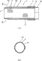
Fig. 4 is the expression Exhaust gas purifying device, wherein: be that sectional view, (B) are the sectional views along the X-X line of A (A);
What Fig. 5 represented is the interior pipe of Exhaust gas purifying device, wherein: be that rolled state figure, (B) are unfolded drawings (A).
Exhaust gas purifying device of the present invention is described below with reference to the accompanying drawings.And Fig. 1 is the overall diagram that is suitable for the two-wheeled motor vehicle of this Exhaust gas purifying device, and Fig. 2 is the part enlarged view of Exhaust gas purifying device, and Fig. 3 is a plane perspective view.
Referring to Fig. 1-Fig. 3, the vent systems of two-wheel car engine 1 has downwards after the extending of cylinder part 1a, the outlet pipe 2 of right lateral bending rearward again, expansion tube 3 that links to each other with this outlet pipe 2, rearward extends along the car body right flank and the sleeve 4 that links to each other with this expansion tube 3, outlet pipe 2 is made of the outlet pipe 5 of motor 1 one sides and the outer tube 6 (Fig. 2) of expansion tube 3 one sides.
Therefore, Exhaust gas purifying device 7 of the present invention forms on the periphery of above-mentioned outer tube 6, and the outside is covered by thermal insulation protection device 8, simultaneously, shown in Fig. 2,3, is arranged on the below of motor 1.Like this, prevent from engine components are brought the baneful influence of heat by this protector 8.
Exhaust gas purifying device 7 as shown in Figure 4, have above-mentioned outer tube 6, be arranged on interior pipe 10 in this outer tube 6, be installed in the dictyosome 11 that constitutes by dividing plate between this outer tube 6 and the interior pipe 10, outer tube 6 shown in (B) among the figure, be to lump together the tubular that forms by 2 detached bodys, and the diameter of axial direction changes.
Promptly, the front end of outer tube 6 forms minor diameter 6a, make the form that the rearward end of above-mentioned outlet pipe 5 can be embedded, intermediate portion 6b then makes the diameter that forms the certain intervals gap with interior pipe 10, rearward end is the major diameter part 6c that can be used to install above-mentioned dictyosome 11, and the 6d of basic courses department then has the diameter in the joint that can embed above-mentioned expansion tube 2.
Like this, interior pipe 10 is welded on by modes such as spot welding on the minor diameter 6a of above-mentioned outer tube 6 along circumferencial direction, supports with cantilevered fashion.
It is axial the stretching that produces with the thermal expansion difference of interior pipe 10 along with outer tube 6 in order to absorb that this cantilever type supports, and the rear end side outer tube 6 that does not support and the variation in the gap between the interior pipe 10 are prevented by above-mentioned dictyosome 11.Thereby, pipe 10 in this dictyosome 11 retrains on radial direction, and allow moving vertically, for example form along circumferencial direction and form snakelike bending.
And should in pipe 10 be rolled into tubular by 1 punched-plate and make.And this punched-plate 10a forms one jiao of shape that cuts a little otch by rectangle shown in the unfolded drawing among Fig. 5 (B), and the end of a side forms weld part e, constitutes coincidence part f, f with this adjacent relative both sides portion on one side.
Like this, this punched-plate 10a is curled, allow coincidence part f, f overlap, thereby form the tubular shown in this figure (A).
Therefore, the place except that above-mentioned weld part e and coincidence part f, f is provided with a plurality of vent h in this punched-plate 10a ..., in addition, catalyst is held in the place outside weld part e.
Promptly, except that weld part e and coincidence part f, f, carry out punching, form a lot of vent h ... repair in surface and the inside of weld part e then, under this state, go out concavo-convex coarse texture in surface Machining, carry out the quality adjustment, on this basis, coating is the catalyst that keynote is mixed with a small amount of rhodium (Rh) with platinum (Pt) for example.
Like this, the place outside the weld part e is attached with catalyst, becomes catalyst and holds face, and weld part e then becomes the non-face of holding of catalyst.
Then, this punched-plate 10a is rolled into the such tubular of Fig. 5 (A), weld part e (the non-face of holding of catalyst) along the circumferential direction forms, and is made by otch and not form coincidence part on the weld part e.
Then, carrying out spot welding (X mark among the figure) at several places of coincidence part f, f engages.
In addition, should in pipe 10 when being welded on above-mentioned outer tube 6, as Fig. 4 (A) along shown in the figure (B) of the sectional view of X-X line like that, the spot welding that the interior Zhou Jinhang of the periphery of the weld part e of interior pipe 10 and the minor diameter 6a of outer tube 6 connects airtight, on weld part e, there is not vent, and smooth outer surface, thereby bond strength height.
And in above-mentioned expansion tube 3, also be provided with oil groove portion 12 as shown in Figure 2.This oil groove portion 12 forms white cigarette in order to prevent that fuel material is not sneaked in the waste gas of discharging from motor, prevent that the problem of adhering on outlet pipe is provided with, and it is arranged on the position overhead highly minimum in the exhaust passageway usually.
Like this, flow to the oil drainage hole that oil plant in this oil groove portion 12 do not go out in then by figure and discharge when for example arriving certain amount, perhaps connecting pipeline on oil drainage hole utilizes as lubricant oil again.
Here, above-mentioned Exhaust gas purifying device 7 is configured in the top of these oil groove portion 12 upstream sides and higher direction.
Thereby, even for example not the oil plant of combustion owing to the effect of air-flow is forced to blow in the oil groove 12, thereby reduced adhering to and piling up of fuel material not attached on the Exhaust gas purifying device 7.Therefore, problems such as white fuming, engine performance deterioration have been reduced.
According to the above, the waste gas of discharging from motor 1 is inner and mobile to expansion tube 3 by outlet pipe 2.Therefore, waste gas is when the Exhaust gas purifying device 7, contacts with catalyst in the interior pipe 10, promoted oxidation reaction, thereby purified unburned part contained in the waste gas.
And high temperature and low temperature occur repeatedly in this Exhaust gas purifying device 7, and the structure of this device all has firm resisting power to the flexible or vibration that caused by thermal expansion difference, impact etc.
In a word, the weld part e of punched-plate 10a is not only owing to have vent and have as the non-smooth surface quality of holding face of catalyst and the bond strength height, and because the power of cantilevered fashion on can not bearing axially.
In addition, interior pipe 10 is made by 1 punched-plate 10a, and pipe 10 o'clock coincidence part f, f just can finish welding in forming, thereby operation is very simple.
In addition, because this Exhaust gas purifying device 7 is configured in oil groove portion 12 upstream sides, can adhere to not fuel material on the Exhaust gas purifying device 7, thereby can suppress problems such as white fuming, engine performance deterioration.
Owing to be configured in the below of motor 1, can reach compact more again, have in order to promote catharsis again catalyst is remained on the condition of high temperature, isolate but its heat can pass through hot Isolation protector 8, thereby engine components are not had harmful effect.In Exhaust gas purifying device, catalyst preferably is maintained at higher temperature to accelerate catharsis, the Exhaust gas purifying device adjacent engine is provided with can receives this effect.Yet this set can produce a problem, is exactly the influence that the parts of motor may be subjected to the high temperature of catalyst.In order to address this problem, in the present invention, the outside of Exhaust gas purifying device 7 is covered by the hot Isolation protector 8 that the periphery around Exhaust gas purifying device 7 is provided with.By the protector 8 of such setting,, also can make engine components avoid the influence of catalyst high temperature even Exhaust gas purifying device 7 is arranged near the motor 1 and catalyst remains on high temperature.
Above-mentioned Exhaust gas purifying device of the present invention is owing to be the non-face of holding of catalyst that setting does not have catalyst on the position of the vent of a pipe part during avoiding, with this catalyst non-hold face as with the weld assembly of outlet pipe, in addition, can a lot of vents be set inside and outside place of circulating at interior pipe, catalyst is held on surface at these parts, and except that above-mentioned formation vent parts, dispose the weld part of managing in this with above-mentioned outlet pipe, simultaneously with the surface at this position as the non-face of holding of catalyst, thereby improved the bond strength with outlet pipe, can realize its long lifetime.
Form the non-face of holding of catalyst in addition by circumferencial direction, thereby avoided the thermal expansion of interior pipe and outlet pipe to look into the flexible influence that brings that causes.
And interior pipe is by 1 punched-plate moulding, can simple moulding.
Owing to be the upstream that Exhaust gas purifying device is configured in oil groove portion, can not damage purification function, and be configured in the below of motor again, can also become more compact.
Claims (6)
1. the Exhaust gas purifying device of a motor (7), comprise an interior interior pipe (10) of outlet pipe (6) that can install to motor (1), pipe forms by a monoblock flat board (10a) is rolled into tubular in described, interior pipe have a plurality of formation thereon vent (h) and be coated with the inner and outer surface of catalyst
The only selection area of pipe (10) formation in described of described vent (h), engine exhaust can be managed (10) in this selection area is described by the vent turnover,
Inner and outer surface at the described selection area of interior pipe (10) is loaded with described catalyst,
Pipe (10) has one first and is welded to connect part (f) and one second and is welded to connect partly (e) in described, be welded to connect part first, intersection (the f of dull and stereotyped (10a), f) soldered and pipe (10) in forming, be welded to connect part second, this engine exhaust emission control device (7) is soldered to the outlet pipe (6) of motor (1), and first and second are welded to connect part (f, e) do not have catalyst and/or vent (h), it is characterized in that:
Pipe (10) one ends are welded to outlet pipe (6) along circumference in described, and described interior pipe (10) the other end is radially not removable but supported movably vertically.
2. engine exhaust emission control device as claimed in claim 1 is characterized in that: above-mentioned catalyst is non-, and to hold face be that circumferencial direction along interior pipe forms.
3. engine exhaust emission control device as claimed in claim 1 or 2 is characterized in that: above-mentioned interior pipe is curled into tubular by 1 punched-plate and forms, and wherein, punched-plate has a plurality of vents in whole surface distributed except portion of being welded to connect and coincidence part.
4. engine exhaust emission control device as claimed in claim 1 or 2 is characterized in that: above-mentioned Exhaust gas purifying device is configured in the upstream of the oil groove portion of exhaust passageway foot formation.
5. engine exhaust emission control device as claimed in claim 1 or 2 is characterized in that: above-mentioned Exhaust gas purifying device is that the hot Isolation protector by the adjacency motor is provided with.
6. motor purification plant as claimed in claim 1 or 2 is characterized in that: a constraint component (11) is radially inwardly managed the other end of (10) and is allowed the other end axial motion in the constraint around the other end setting of interior pipe.
Applications Claiming Priority (3)
| Application Number | Priority Date | Filing Date | Title |
|---|---|---|---|
| JP21160494A JP3257906B2 (en) | 1994-09-05 | 1994-09-05 | Engine exhaust purification device |
| JP211604/94 | 1994-09-05 | ||
| JP211604/1994 | 1994-09-05 |
Publications (2)
| Publication Number | Publication Date |
|---|---|
| CN1127836A CN1127836A (en) | 1996-07-31 |
| CN1118619C true CN1118619C (en) | 2003-08-20 |
Family
ID=16608521
Family Applications (1)
| Application Number | Title | Priority Date | Filing Date |
|---|---|---|---|
| CN95117718A Expired - Fee Related CN1118619C (en) | 1994-09-05 | 1995-09-05 | Engine exhaust purifying device |
Country Status (7)
| Country | Link |
|---|---|
| US (1) | US5729972A (en) |
| EP (1) | EP0699829B1 (en) |
| JP (1) | JP3257906B2 (en) |
| CN (1) | CN1118619C (en) |
| DE (1) | DE69520532T2 (en) |
| ES (1) | ES2155491T3 (en) |
| TW (1) | TW297851B (en) |
Families Citing this family (16)
| Publication number | Priority date | Publication date | Assignee | Title |
|---|---|---|---|---|
| JP3644762B2 (en) * | 1996-07-09 | 2005-05-11 | 本田技研工業株式会社 | Exhaust gas purification device |
| SE9700459L (en) * | 1997-02-10 | 1998-02-23 | Mats Tikka | Catalytic converter for two-stroke engine with heat exchanger |
| JP3433097B2 (en) * | 1998-04-20 | 2003-08-04 | 本田技研工業株式会社 | Insulated exhaust pipe for engine |
| ES2198831T3 (en) * | 1999-10-20 | 2004-02-01 | UMICORE AG & CO. KG | SILENCER CONTAINING A CATALYTIC DEVICE FOR TWO-TIME ENGINES AND CATALYTIC DEVICE FOR THE SAME. |
| JP2007023802A (en) * | 2005-07-12 | 2007-02-01 | Yamaha Motor Co Ltd | Saddle riding type vehicle |
| JP4673789B2 (en) * | 2006-05-16 | 2011-04-20 | 本田技研工業株式会社 | Exhaust pipe |
| US20080041043A1 (en) * | 2006-08-16 | 2008-02-21 | Andersen Eric H | Exhaust treatment devices and methods for reducing sound using the exhaust treatment devices |
| JP2008064068A (en) * | 2006-09-11 | 2008-03-21 | Yamaha Motor Co Ltd | Motorcycle |
| JP2011064192A (en) * | 2009-08-21 | 2011-03-31 | Nichias Corp | Automobile exhaust pipe |
| JP5373547B2 (en) * | 2009-10-21 | 2013-12-18 | 本田技研工業株式会社 | Step peripheral structure of saddle riding type vehicle |
| JP2013036422A (en) * | 2011-08-09 | 2013-02-21 | Suzuki Motor Corp | Exhaust pipe structure of internal combustion engine |
| JP6031244B2 (en) * | 2012-03-28 | 2016-11-24 | 本田技研工業株式会社 | Exhaust device for saddle riding type vehicle |
| WO2016098907A1 (en) * | 2014-12-19 | 2016-06-23 | ヤマハ発動機株式会社 | Saddle-type vehicle |
| JP6364123B2 (en) | 2015-03-24 | 2018-07-25 | 本田技研工業株式会社 | Motorcycle exhaust system |
| CN104791063A (en) * | 2015-04-11 | 2015-07-22 | 成都陵川特种工业有限责任公司 | High-heat-dissipation exhaust pipe |
| US11319847B2 (en) * | 2018-09-19 | 2022-05-03 | Tenneco Automotive Operating Company Inc. | Exhaust device with noise suppression system |
Citations (3)
| Publication number | Priority date | Publication date | Assignee | Title |
|---|---|---|---|---|
| FR2460709A1 (en) * | 1979-07-09 | 1981-01-30 | Renault | Protective device for catalytic purifier in vehicle exhaust system - comprises small auxiliary catalytic reactor installed upstream of purifier |
| DE3715040A1 (en) * | 1987-05-06 | 1987-11-19 | Karl Schmidt | Punched strip catalyst |
| CN1052355A (en) * | 1989-12-02 | 1991-06-19 | 底古萨股份公司 | Internal-combustion engine is the arrangement for catalytic purification of exhaust gases of two-stroke internal-combustion engine particularly |
Family Cites Families (6)
| Publication number | Priority date | Publication date | Assignee | Title |
|---|---|---|---|---|
| JPH0621559B2 (en) * | 1984-10-16 | 1994-03-23 | ヤマハ発動機株式会社 | Exhaust pipe of 2-cycle engine |
| US5104627A (en) * | 1988-12-19 | 1992-04-14 | Usui Kokusai Sangyo Kabushiki Kaisha | Exhaust gas cleaning apparatus |
| JP2816989B2 (en) * | 1989-08-29 | 1998-10-27 | スズキ株式会社 | Exhaust gas purification device for internal combustion engine |
| KR920007887B1 (en) * | 1989-08-29 | 1992-09-18 | 스즈키 지도오샤 고오교오 가부시키가이샤 | Exhaust gas cleaning device for internal combustion engine |
| JP2952997B2 (en) * | 1990-08-27 | 1999-09-27 | スズキ株式会社 | Exhaust gas purification device |
| JPH04116219A (en) * | 1990-09-06 | 1992-04-16 | Suzuki Motor Corp | Exhaust gas purification device |
-
1994
- 1994-09-05 JP JP21160494A patent/JP3257906B2/en not_active Expired - Fee Related
-
1995
- 1995-09-05 US US08/523,768 patent/US5729972A/en not_active Expired - Fee Related
- 1995-09-05 TW TW084109273A patent/TW297851B/zh active
- 1995-09-05 CN CN95117718A patent/CN1118619C/en not_active Expired - Fee Related
- 1995-09-05 EP EP95113918A patent/EP0699829B1/en not_active Expired - Lifetime
- 1995-09-05 ES ES95113918T patent/ES2155491T3/en not_active Expired - Lifetime
- 1995-09-05 DE DE69520532T patent/DE69520532T2/en not_active Expired - Fee Related
Patent Citations (3)
| Publication number | Priority date | Publication date | Assignee | Title |
|---|---|---|---|---|
| FR2460709A1 (en) * | 1979-07-09 | 1981-01-30 | Renault | Protective device for catalytic purifier in vehicle exhaust system - comprises small auxiliary catalytic reactor installed upstream of purifier |
| DE3715040A1 (en) * | 1987-05-06 | 1987-11-19 | Karl Schmidt | Punched strip catalyst |
| CN1052355A (en) * | 1989-12-02 | 1991-06-19 | 底古萨股份公司 | Internal-combustion engine is the arrangement for catalytic purification of exhaust gases of two-stroke internal-combustion engine particularly |
Also Published As
| Publication number | Publication date |
|---|---|
| JPH0874566A (en) | 1996-03-19 |
| EP0699829B1 (en) | 2001-04-04 |
| EP0699829A3 (en) | 1996-05-01 |
| US5729972A (en) | 1998-03-24 |
| DE69520532D1 (en) | 2001-05-10 |
| DE69520532T2 (en) | 2001-07-12 |
| CN1127836A (en) | 1996-07-31 |
| TW297851B (en) | 1997-02-11 |
| ES2155491T3 (en) | 2001-05-16 |
| JP3257906B2 (en) | 2002-02-18 |
| EP0699829A2 (en) | 1996-03-06 |
Similar Documents
| Publication | Publication Date | Title |
|---|---|---|
| CN1118619C (en) | Engine exhaust purifying device | |
| US6623704B1 (en) | Apparatus and method for manufacturing a catalytic converter | |
| CN102027215B (en) | Exhaust treatment device and manufacturing method thereof | |
| US7334334B2 (en) | Automotive exhaust component and method of manufacture | |
| JP3988028B2 (en) | EGR device for engine | |
| CN1924315A (en) | Muffler | |
| US7685714B2 (en) | Automotive exhaust component and process of manufacture | |
| CN1289802C (en) | Exhaust gas purification apparatus | |
| US7252808B2 (en) | Automotive exhaust component and method of manufacture | |
| CN101547731B (en) | Automotive exhaust component and method of manufacture | |
| US6200538B1 (en) | Exhaust gas system suitable for retrofitting exhaust gas catalytic converters in motorcycles | |
| CN1139720C (en) | Catalyic converter unit with catalyst substrate and device and method for producing same | |
| US7713494B2 (en) | Exhaust purification device | |
| CN1102195C (en) | Two stroke engine silencing device | |
| WO1998034726A3 (en) | Honeycomb body with cross-sectional area framed in the interior, particularly for small-power motors | |
| JPH10141052A (en) | Manufacture of ceramic catalyst converter and ceramic catalyst converter | |
| JPH10311214A (en) | Exhaust system having catalyst | |
| JP4147156B2 (en) | Exhaust purification device | |
| KR100187976B1 (en) | A flange structure for catalyst converter in a car | |
| JP3133279U (en) | Motorcycle exhaust pipe catalyst device | |
| JP2003113711A (en) | Exhaust gas catalyst device, manufacturing method of the same, and muffler unit with exhaust gas catalyst device | |
| AU2009212948B2 (en) | Catalytic converter for internal combustion engine exhaust system | |
| KR20020043091A (en) | Closed Coupled Converter structure using metal catalystic | |
| JP2020084810A (en) | Tail pipe | |
| KR20030037933A (en) | Method of manufacturing a catalytic converter |
Legal Events
| Date | Code | Title | Description |
|---|---|---|---|
| C06 | Publication | ||
| PB01 | Publication | ||
| C10 | Entry into substantive examination | ||
| SE01 | Entry into force of request for substantive examination | ||
| C14 | Grant of patent or utility model | ||
| GR01 | Patent grant | ||
| C17 | Cessation of patent right | ||
| CF01 | Termination of patent right due to non-payment of annual fee |
Granted publication date: 20030820 Termination date: 20100905 |