CN111843769B - Automatic polishing machine for vertical bamboo flute wall - Google Patents
Automatic polishing machine for vertical bamboo flute wall Download PDFInfo
- Publication number
- CN111843769B CN111843769B CN202010738920.9A CN202010738920A CN111843769B CN 111843769 B CN111843769 B CN 111843769B CN 202010738920 A CN202010738920 A CN 202010738920A CN 111843769 B CN111843769 B CN 111843769B
- Authority
- CN
- China
- Prior art keywords
- rod
- gear
- polishing
- bamboo flute
- vertical bamboo
- Prior art date
- Legal status (The legal status is an assumption and is not a legal conclusion. Google has not performed a legal analysis and makes no representation as to the accuracy of the status listed.)
- Active
Links
Images


Classifications
-
- B—PERFORMING OPERATIONS; TRANSPORTING
- B24—GRINDING; POLISHING
- B24B—MACHINES, DEVICES, OR PROCESSES FOR GRINDING OR POLISHING; DRESSING OR CONDITIONING OF ABRADING SURFACES; FEEDING OF GRINDING, POLISHING, OR LAPPING AGENTS
- B24B27/00—Other grinding machines or devices
- B24B27/0076—Other grinding machines or devices grinding machines comprising two or more grinding tools
-
- B—PERFORMING OPERATIONS; TRANSPORTING
- B24—GRINDING; POLISHING
- B24B—MACHINES, DEVICES, OR PROCESSES FOR GRINDING OR POLISHING; DRESSING OR CONDITIONING OF ABRADING SURFACES; FEEDING OF GRINDING, POLISHING, OR LAPPING AGENTS
- B24B41/00—Component parts such as frames, beds, carriages, headstocks
- B24B41/02—Frames; Beds; Carriages
-
- B—PERFORMING OPERATIONS; TRANSPORTING
- B24—GRINDING; POLISHING
- B24B—MACHINES, DEVICES, OR PROCESSES FOR GRINDING OR POLISHING; DRESSING OR CONDITIONING OF ABRADING SURFACES; FEEDING OF GRINDING, POLISHING, OR LAPPING AGENTS
- B24B41/00—Component parts such as frames, beds, carriages, headstocks
- B24B41/06—Work supports, e.g. adjustable steadies
- B24B41/067—Work supports, e.g. adjustable steadies radially supporting workpieces
-
- B—PERFORMING OPERATIONS; TRANSPORTING
- B24—GRINDING; POLISHING
- B24B—MACHINES, DEVICES, OR PROCESSES FOR GRINDING OR POLISHING; DRESSING OR CONDITIONING OF ABRADING SURFACES; FEEDING OF GRINDING, POLISHING, OR LAPPING AGENTS
- B24B47/00—Drives or gearings; Equipment therefor
- B24B47/10—Drives or gearings; Equipment therefor for rotating or reciprocating working-spindles carrying grinding wheels or workpieces
- B24B47/12—Drives or gearings; Equipment therefor for rotating or reciprocating working-spindles carrying grinding wheels or workpieces by mechanical gearing or electric power
-
- B—PERFORMING OPERATIONS; TRANSPORTING
- B24—GRINDING; POLISHING
- B24B—MACHINES, DEVICES, OR PROCESSES FOR GRINDING OR POLISHING; DRESSING OR CONDITIONING OF ABRADING SURFACES; FEEDING OF GRINDING, POLISHING, OR LAPPING AGENTS
- B24B5/00—Machines or devices designed for grinding surfaces of revolution on work, including those which also grind adjacent plane surfaces; Accessories therefor
- B24B5/02—Machines or devices designed for grinding surfaces of revolution on work, including those which also grind adjacent plane surfaces; Accessories therefor involving centres or chucks for holding work
- B24B5/04—Machines or devices designed for grinding surfaces of revolution on work, including those which also grind adjacent plane surfaces; Accessories therefor involving centres or chucks for holding work for grinding cylindrical surfaces externally
-
- B—PERFORMING OPERATIONS; TRANSPORTING
- B24—GRINDING; POLISHING
- B24B—MACHINES, DEVICES, OR PROCESSES FOR GRINDING OR POLISHING; DRESSING OR CONDITIONING OF ABRADING SURFACES; FEEDING OF GRINDING, POLISHING, OR LAPPING AGENTS
- B24B5/00—Machines or devices designed for grinding surfaces of revolution on work, including those which also grind adjacent plane surfaces; Accessories therefor
- B24B5/35—Accessories
-
- B—PERFORMING OPERATIONS; TRANSPORTING
- B24—GRINDING; POLISHING
- B24B—MACHINES, DEVICES, OR PROCESSES FOR GRINDING OR POLISHING; DRESSING OR CONDITIONING OF ABRADING SURFACES; FEEDING OF GRINDING, POLISHING, OR LAPPING AGENTS
- B24B5/00—Machines or devices designed for grinding surfaces of revolution on work, including those which also grind adjacent plane surfaces; Accessories therefor
- B24B5/36—Single-purpose machines or devices
-
- B—PERFORMING OPERATIONS; TRANSPORTING
- B24—GRINDING; POLISHING
- B24B—MACHINES, DEVICES, OR PROCESSES FOR GRINDING OR POLISHING; DRESSING OR CONDITIONING OF ABRADING SURFACES; FEEDING OF GRINDING, POLISHING, OR LAPPING AGENTS
- B24B5/00—Machines or devices designed for grinding surfaces of revolution on work, including those which also grind adjacent plane surfaces; Accessories therefor
- B24B5/50—Machines or devices designed for grinding surfaces of revolution on work, including those which also grind adjacent plane surfaces; Accessories therefor characterised by a special design with respect to properties of the material of non-metallic articles to be ground, e.g. strings
-
- B—PERFORMING OPERATIONS; TRANSPORTING
- B24—GRINDING; POLISHING
- B24B—MACHINES, DEVICES, OR PROCESSES FOR GRINDING OR POLISHING; DRESSING OR CONDITIONING OF ABRADING SURFACES; FEEDING OF GRINDING, POLISHING, OR LAPPING AGENTS
- B24B9/00—Machines or devices designed for grinding edges or bevels on work or for removing burrs; Accessories therefor
- B24B9/002—Machines or devices designed for grinding edges or bevels on work or for removing burrs; Accessories therefor for travelling workpieces
-
- B—PERFORMING OPERATIONS; TRANSPORTING
- B24—GRINDING; POLISHING
- B24B—MACHINES, DEVICES, OR PROCESSES FOR GRINDING OR POLISHING; DRESSING OR CONDITIONING OF ABRADING SURFACES; FEEDING OF GRINDING, POLISHING, OR LAPPING AGENTS
- B24B9/00—Machines or devices designed for grinding edges or bevels on work or for removing burrs; Accessories therefor
- B24B9/02—Machines or devices designed for grinding edges or bevels on work or for removing burrs; Accessories therefor characterised by a special design with respect to properties of materials specific to articles to be ground
- B24B9/18—Machines or devices designed for grinding edges or bevels on work or for removing burrs; Accessories therefor characterised by a special design with respect to properties of materials specific to articles to be ground of wood
Abstract
The invention relates to a grinding machine, in particular to an automatic grinding machine for a vertical bamboo flute wall. The automatic flute wall grinding machine is simple to operate and uniform in grinding degree of all parts of the flute wall. An automatic polishing machine for vertical bamboo flute walls comprises: a base; the mounting rack is mounted on the base; the power assembly is arranged on the mounting frame; the flute wall polishing component is arranged on the mounting frame; and the corner polishing component is arranged between the mounting frame and the vertical bamboo flute wall polishing component. According to the vertical bamboo flute wall grinding device, the vertical bamboo flute wall grinding component and the corner grinding component can be driven to work through the power component to grind the vertical bamboo flute wall, the vertical bamboo flute wall does not need to be manually ground, and the operation is simple; the clamped vertical bamboo flute can be automatically driven to move, so that the polishing degree of each part of the vertical bamboo flute wall is uniform; the invention can replace the parts to be polished, and the replacement operation is simpler.
Description
Technical Field
The invention relates to a polisher, in particular to an automatic polisher for a vertical bamboo flute wall.
Background
The vertical bamboo flute is an ancient Chinese-style musical instrument, is mellow and soft in tone, quiet and elegant, and is suitable for solo and repeated playing. It is generally made of bamboo with blow holes at the upper end. The flute is divided into six-hole flute and eight-hole flute according to the number of the sound holes, wherein the sound holes of the six-hole flute are one in front of five and one behind the sound holes of the six-hole flute, and the sound holes of the eight-hole flute are one in front of seven and one behind the sound holes of the eight-hole flute. All are single-tube and vertical blowing. The eight-hole xiao is a modern improved product.
When making the xiao, need polish to blowing the vertical bamboo flute wall of hole department specially, prevent that the vertical bamboo flute wall of hole department from cutting the lip of blowing the vertical bamboo flute person, can improve the tone quality simultaneously, when polishing the vertical bamboo flute wall of hole department at present, mostly use abrasive paper to polish the vertical bamboo flute wall of blowing the hole department manually, this kind of polishing mode intensity of labour is great, and the vertical bamboo flute wall degree of polishing everywhere is also too even.
Therefore, the need of developing an automatic polishing machine for the vertical bamboo flute wall, which is simple in operation and uniform in polishing degree of all parts of the vertical bamboo flute wall, is urgently needed.
Disclosure of Invention
In order to overcome present manual use abrasive paper and polish the vertical bamboo flute wall of blowing hole department, intensity of labour is great, the vertical bamboo flute wall degree of polishing everywhere also too even shortcoming, and the technical problem that solves is: the automatic flute wall grinding machine is simple to operate and uniform in grinding degree of all parts of the flute wall.
The technical scheme of the invention is as follows: an automatic polishing machine for vertical bamboo flute walls comprises: a base; the mounting rack is mounted on the base; the power assembly is arranged on the mounting frame; the flute wall polishing component is arranged on the mounting rack; and the corner polishing component is arranged between the mounting frame and the flute wall polishing component.
Further, the power assembly comprises: the speed reducing motor is arranged on the mounting frame; the first rotating rod is arranged on an output shaft of the speed reducing motor through a coupler; the first gear is connected to the first rotating rod in a key mode.
Further, vertical bamboo flute wall grinding component is including: the polishing ring is rotatably arranged on the mounting frame; the second gear is connected with two sides of the polishing circular ring in a key mode, and the second gear on one side is meshed with the first gear; the first guide sleeve is arranged on one side, close to the polishing circular ring, of the mounting frame; the gear shaft is rotatably arranged on the first guide sleeve, and the second gear on the other side is meshed with the gear shaft; the first bevel gear is connected to one side of the gear shaft in a key way; the first support frame is arranged on the mounting frame; the first cylinder is rotatably arranged on the first support frame; a first profiled bar slidably mounted within the first cylinder; the prismatic rod is arranged on the first special-shaped rod and is in rotating and sliding fit with the mounting rack; the right-angle rod is rotatably arranged on the first special-shaped rod; the internal grinding wheel is arranged on the prismatic rod in a sliding manner; the vertical rod is rotatably arranged on the mounting frame and is in sliding connection with the internal grinding wheel; and the second bevel gear is connected to the vertical rod in a key mode and is meshed with the first bevel gear.
Further, the corner grinding component comprises: the second supporting frames are symmetrically arranged on the mounting frame; the third gear is rotatably arranged on the second support frame; the second special-shaped rod is slidably mounted on the third gear; the connecting rod is arranged between the second special-shaped rods and is simultaneously connected with the right-angle rods; the corner polishing wheel is arranged on the second special-shaped rod in a sliding mode, and is simultaneously matched with the mounting frame in a sliding and rotating mode; the first belt pulley is arranged on the second special-shaped rod on one side and the first cylinder; and the first flat belt is arranged between the first belt pulleys.
Further, the method also comprises the following steps: the sliding rails are arranged on two sides of the base; the supporting rod is arranged on the sliding rail in a sliding manner; the placing ring is arranged between the supporting rods; the pressure lever is arranged on the placing ring in a sliding way; the first spring is installed between the pressure rod and the placing ring.
Further, the method also comprises the following steps: the guide rail is arranged on one side of the base; the second cylinder is rotatably arranged on the inner side of the guide rail and is provided with a spiral groove; the connecting rod is arranged on the placing ring and is in sliding fit with the spiral groove; at least two second guide sleeves are arranged on the base; the pushing rod is arranged between the second guide sleeves in a sliding mode and matched with the supporting rod; the rotating shaft is arranged on one side of the second cylinder and is in rotary fit with the base; a long rack gear mounted on the first gear; the fourth gear is arranged on the rotating shaft in a sliding mode and is matched with the strip teeth, and the fourth gear is also matched with the push rod; the second spring is arranged between the fourth gear and the rotating shaft; the supporting sleeve is arranged on the base; the second rotating rod is rotatably arranged in the supporting sleeve; the overrunning clutch is arranged on the second rotating rod; the fifth gear is arranged on the overrunning clutch and meshed with the fourth gear; the second belt pulley is arranged on the first rotating rod and the second rotating rod; and the second flat belt is arranged between the second pulleys.
The beneficial effects are that: 1. the vertical bamboo flute wall polishing component and the corner polishing component can be driven by the power component to work, the vertical bamboo flute wall is polished, manual polishing of the vertical bamboo flute wall is not needed, and the operation is simple;
2. the clamped vertical bamboo flute can be automatically driven to move without manual pushing, so that the polishing degree of each part of the vertical bamboo flute wall is uniform, and the workload of workers is reduced;
3. the invention can replace the parts to be polished, and the replacement operation is simpler.
Drawings
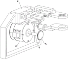
Fig. 1 is a schematic perspective view of the present invention.
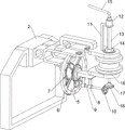
Fig. 2 is a schematic perspective view of the power module of the present invention.
FIG. 3 is a schematic perspective view of a vertical bamboo flute wall polishing component according to the present invention.
Figure 4 is a perspective view of the corner grinding assembly of the present invention.
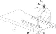
Fig. 5 is a perspective view of the clamping assembly of the present invention.
FIG. 6 is a schematic view of a first partial body structure according to the present invention.
FIG. 7 is a schematic view of a second partial body structure according to the present invention.
In the reference symbols: a base, 2.. a mounting frame, 3.. a reduction motor, 4.. a first rotating rod, 5.. a first gear, 6.. a grinding ring, 7.. a second gear, 8.. a first guide sleeve, 9.. a gear shaft, 10.. a first bevel gear, 11.. a first support frame, 12.. a first cylinder, 13.. a first deformed rod, 14.. a prismatic rod, 15.. a right-angled rod, 16.. an inner grinding wheel, 17.. a vertical rod, 18.. a second tapered gear, 19.. a second support frame, 20.. a third gear, 21.. a second deformed rod, 22.. a connecting rod, 23.. an corner grinding wheel, 24.. a first grinding wheel, 25.. a first belt, 26.. a first sliding rod, 29.. a first sliding rod, 30.. a first sliding rod, 17.. a first supporting rod, 12.. a second sliding rod, 21.. a second deformed rod, 22.. a sliding rod, 30.. a spring, 29.. a first sliding rod, a guide rail, 32.. second cylinder, 33.. helical groove, 34.. connecting rod, 35.. second guide sleeve, 36.. push rod, 37.. rotating shaft, 38.. long rack tooth, 39.. fourth gear, 40.. second spring, 41.. support sleeve, 42.. second rotating rod, 43.. fifth gear, 44.. overrunning clutch, 45.. second belt wheel, 46.. second flat belt.
Detailed Description
Embodiments of the present invention are described in detail below with reference to the accompanying drawings.
Example 1
An automatic flute wall grinding machine is shown in figures 1-4 and comprises a base 1, a mounting frame 2, a power assembly, a flute wall grinding assembly and a corner grinding assembly, wherein the mounting frame 2 is fixedly connected to the left side of the upper portion of the base 1 through bolts, the power assembly is arranged on the mounting frame 2, the flute wall grinding assembly is further arranged on the mounting frame 2, and the corner grinding assembly is arranged between the mounting frame 2 and the flute wall grinding assembly.
When the device is used for polishing the vertical bamboo flute wall at the position of the blowing hole, the power assembly is controlled to start working at first, the power assembly can drive the vertical bamboo flute wall polishing assembly and the corner polishing assembly to work, then the position of the blowing hole of the vertical bamboo flute is contacted with the vertical bamboo flute wall polishing assembly and the corner polishing assembly, the vertical bamboo flute wall at the position of the blowing hole is polished, the power assembly is controlled to stop working after polishing is completed, and then the polished vertical bamboo flute is taken away and collected.
The power assembly comprises a speed reducing motor 3, a first rotating rod 4 and a first gear 5, the speed reducing motor 3 is fixedly connected to the inner side of the upper portion of the mounting frame 2 through a bolt, the first rotating rod 4 is connected to an output shaft of the speed reducing motor 3 through a coupler, and the first gear 5 is connected to the right side of the first rotating rod 4 through a key.
When the device is used for polishing the vertical bamboo flute wall at the position of the blowing hole, firstly, the gear motor 3 is controlled to start working, the gear motor 3 can drive the first gear 5 to rotate through the first rotating rod 4, the first gear 5 can drive the vertical bamboo flute wall polishing component to work, the vertical bamboo flute wall polishing component can drive the corner polishing component to work when working, at the moment, the position of the blowing hole of the vertical bamboo flute can be in contact with the vertical bamboo flute wall polishing component and the corner polishing component, the polishing work is carried out, after the polishing work is finished, the gear motor 3 is controlled to stop working, and the vertical bamboo flute is taken away and collected.
The flute-wall polishing component comprises a polishing ring 6, a second gear 7, a first guide sleeve 8, a gear shaft 9, a first bevel gear 10, a first support frame 11, a first cylinder 12, a first special-shaped rod 13, a prismatic rod 14, a right-angle rod 15, an internal polishing wheel 16, a vertical rod 17 and a second bevel gear 18, wherein the polishing ring 6 is rotatably arranged at the middle position of the upper part of the mounting frame 2, the second gear 7 is respectively connected with the left side and the right side of the polishing ring 6 in a key way, the second gear 7 at the left side is meshed with the first gear 5, the first guide sleeve 8 is fixedly connected on the mounting frame 2 at the right side of the polishing ring 6 through bolts, the gear shaft 9 is rotatably arranged at the lower part of the first guide sleeve 8, the second gear 7 at the right side is meshed with the gear shaft 9, the first bevel gear 10 is connected at the right side of the gear shaft 9 in a key way, the first support frame 11 is fixedly connected at the right side of the upper part of the mounting frame 2 through bolts, the first support frame 11 is rotatably arranged with the first cylinder 12, first abnormal shape pole 13 is equipped with to slidingtype in the first drum 12, first abnormal shape pole 13 sub-unit connection has prismatic pole 14, prismatic pole 14 rotates and sliding fit with mounting bracket 2, first abnormal shape pole 13 upper portion rotary type is connected with right angle pole 15, prismatic pole 14 lower part slidingtype is equipped with inside grinding wheel 16, mounting bracket 2 right side rotary type is equipped with montant 17, montant 17 and inside grinding wheel 16 sliding connection, montant 17 lower part key-type is connected with second bevel gear 18, second bevel gear 18 and first bevel gear 10 meshing.
When the first gear 5 rotates, the second gear 7 on the left side of the polishing ring 6 drives the polishing ring 6 and the second gear 7 on the right side of the polishing ring 6 to rotate, the second gear 7 on the right side of the polishing ring 6 rotates to drive the gear shaft 9 and the first bevel gear 10 to rotate, the first bevel gear 10 rotates to drive the second bevel gear 18, the vertical rod 17, the prismatic rod 14, the internal polishing wheel 16, the first special-shaped rod 13 and the first cylinder 12 to rotate, the first cylinder 12 rotates to drive the corner polishing component to work, at the moment, the blowing hole of the flute can be contacted with the polishing ring 6, the internal polishing wheel 16 and the corner polishing component, the polishing ring 6 polishes the flute wall close to the blowing hole, the internal polishing wheel 16 polishes the blowing hole of the flute, the corner polishing component polishes the corner at the blowing hole, and after the polishing work is finished, the reduction motor 3 is controlled to stop working and take the flute down for collection, when the internal grinding wheel 16 needs to be replaced, the right-angle rod 15 can be pulled upwards, the upward movement of the right-angle rod 15 can drive the first special-shaped rod 13 and the prismatic rod 14 to move upwards, the internal grinding wheel 16 can be replaced after the prismatic rod 14 moves to be out of contact with the internal grinding wheel 16, and after the replacement is finished, the right-angle rod 15, the first special-shaped rod 13 and the prismatic rod 14 are controlled to reset.
The corner grinding component comprises a second supporting frame 19, a third gear 20, a second profile rod 21, a connecting rod 22, a corner grinding wheel 23, a first belt pulley 24 and a first flat belt 25, 2 upper portion right sides of mounting bracket have second support frame 19 through the bolt rigid coupling symmetrically around, equal rotary type is equipped with third gear 20 on the second support frame 19, two third gear 20 meshing, third gear 20 middle part all slidingtype is equipped with second deformed bar 21, second deformed bar 21 rotates and slidingtype cooperation with mounting bracket 2, the rotary type is connected with connecting rod 22 between second deformed bar 21 upper portion, connecting rod 22 is connected with right-angle pole 15 simultaneously, second deformed bar 21 lower part slidingtype is equipped with corner grinding wheel 23, corner grinding wheel 23 slides and rotates the formula cooperation with mounting bracket 2 simultaneously, all be equipped with first belt pulley 24 on the second deformed bar 21 upper portion of rear side and the first drum 12, be equipped with first flat belt 25 between the first belt pulley 24.
When the first cylinder 12 rotates, the second special-shaped rod 21 on the rear side is driven to rotate through the first belt pulley 24 and the first flat belt 25, the second special-shaped rod 21 on the rear side rotates to drive the second special-shaped rod 21 on the front side to rotate through the third gear 20, so that the corner polishing wheel 23 is driven to rotate, the corner of the vertical bamboo flute at the position of the hole blowing hole is polished, when the right-angle rod 15 moves upwards, the connecting rod 22 and the second special-shaped rod 21 can be driven to move upwards, therefore, the corner polishing wheel 23 can be replaced, and after the replacement is completed, the right-angle rod 15 is controlled to drive the connecting rod 22 and the second special-shaped rod 21 to reset.
Example 2
On the basis of embodiment 1, as shown in fig. 1, 5, 6 and 7, the portable electronic device further includes a slide rail 26, a support rod 27, a placing ring 28, a press rod 29 and a first spring 30, the slide rail 26 is fixedly connected to the front and rear sides of the right portion of the base 1 through bolts, the support rod 27 is slidably disposed on the slide rail 26, the placing ring 28 is connected between the support rods 27 through bolts, the press rod 29 is slidably disposed on the upper portion of the placing ring 28, and the first spring 30 is connected between the press rod 29 and the placing ring 28.
Before the vertical bamboo flute is polished, the pressure rod 29 can be pulled upwards, the first spring 30 is stretched, the vertical bamboo flute is placed in the placing ring 28, the blow hole of the vertical bamboo flute is located above the left side of the vertical bamboo flute, the pressure rod 29 is loosened, the first spring 30 can reset to drive the pressure rod 29 to reset at the moment, the vertical bamboo flute is fixed, the placing ring 28 can be pushed to move leftwards along the slide rail 26, the vertical bamboo flute is polished, after polishing is completed and the speed reduction motor 3 is closed, the placing ring 28 is controlled to reset, the pressure rod 29 is pulled upwards again, the vertical bamboo flute is taken down and then the pressure rod 29 is loosened, and the pressure rod 29 can automatically reset.
The device also comprises a guide rail 31, a second cylinder 32, a connecting rod 34, a second guide sleeve 35, a pushing rod 36, a rotating shaft 37, a strip tooth 38, a fourth gear 39, a second spring 40, a supporting sleeve 41, a second rotating rod 42, a fifth gear 43, an overrunning clutch 44, a second belt pulley 45 and a second flat belt 46, wherein the right side of the base 1 is fixedly connected with the guide rail 31 through bolts, the inner side of the guide rail 31 is rotatably provided with the second cylinder 32, the second cylinder 32 is provided with a spiral groove 33, the lower part of the placing ring 28 is welded with the connecting rod 34, the connecting rod 34 is in sliding fit with the spiral groove 33, the rear side of the base 1 is fixedly connected with the two second guide sleeves 35 through bolts, the pushing rod 36 is in sliding fit between the second guide sleeves 35, the pushing rod 36 is matched with the supporting rod 27, the left side of the second cylinder 32 is connected with the rotating shaft 37, the rotating shaft 37 is in rotating fit with the base 1, the lower part of the first gear 5 is fixedly connected with the strip tooth 38, the left side of the rotating shaft 37 is provided with the fourth gear 39 in sliding fit with the fourth gear 39, fourth gear 39 and rectangular tooth 38 cooperation, fourth gear 39 also can cooperate with catch bar 36, be connected with second spring 40 between fourth gear 39 and pivot 37, base 1 top front side has support cover 41 through the bolt rigid coupling, support cover 41 internal rotation formula is equipped with second bull stick 42, be equipped with freewheel clutch 44 on the second bull stick 42, be equipped with fifth gear 43 on the freewheel clutch 44, fifth gear 43 and fourth gear 39 meshing, first bull stick 4 left side and second bull stick 42 left side all are equipped with second belt pulley 45, be equipped with second flat belt 46 between the second belt pulley 45.
When the first gear 5 rotates, the long teeth 38 are driven to rotate, so that the fourth gear 39 drives the rotating shaft 37 to slowly rotate, the rotating shaft 37 rotates to drive the placing ring 28 and the supporting rod 27 to move leftwards through the connecting rod 34, while the first gear 5 rotates, the second rotating rod 42 is driven to rotate through the second belt pulley 45 and the second flat belt 46, due to the action of the overrunning clutch 44, the fifth gear 43 does not rotate, when the supporting rod 27 moves to a certain extent, the supporting rod 27 contacts with the pushing rod 36 to drive the pushing rod 36 to move leftwards, so as to push the fourth gear 39 to move leftwards, the second spring 40 is compressed, after the placing ring 28 moves to the leftmost end of the guide rail 31, the fourth gear 39 moves to be not matched with the long teeth 38 and is meshed with the fifth gear 43, at this time, the vertical bamboo flute wall is being polished, after the vertical bamboo flute wall is polished, the speed reduction motor 3 is controlled to drive the first rotating rod 4 to rotate reversely, the second belt pulley 45 can be used for driving the rotating shaft 37 to rotate reversely through the second belt pulley 45, the second flat belt 46, the second rotating rod 42, the fifth gear 43 and the fourth gear 39, so that the placing ring 28 and the supporting rod 27 start to reset, when the placing ring 28 and the supporting rod 27 reset, the second spring 40 also resets, the fourth gear 39 and the push rod 36 reset are driven, after the placing ring 28 and the supporting rod 27 reset, the speed reduction motor 3 is controlled to stop working, therefore, the placing ring 28 does not need to be manually pushed to move, and the workload of workers is reduced.
The above-mentioned embodiments are only preferred embodiments of the present invention, and should not be used to limit the scope of the present invention, so that all equivalent changes made by the contents of the claims of the present invention should be included in the scope of the claims of the present invention.
Claims (3)
1. The utility model provides an automatic polisher of vertical bamboo flute wall, characterized by, including:
a base (1);
the mounting rack (2) is mounted on the base (1);
the power assembly is arranged on the mounting frame (2);
the vertical bamboo flute wall polishing component is arranged on the mounting rack (2);
the corner polishing component is arranged between the mounting frame (2) and the vertical bamboo flute wall polishing component;
the speed reducing motor (3) is arranged on the mounting frame (2);
the first rotating rod (4) is arranged on an output shaft of the speed reducing motor (3) through a coupler;
a first gear (5) which is connected with the first rotating rod (4) in a key way;
the polishing circular ring (6) is rotatably arranged on the mounting frame (2);
the second gear (7) is in key connection with two sides of the polishing circular ring (6), and the second gear (7) on one side is meshed with the first gear (5);
the first guide sleeve (8) is arranged on one side, close to the polishing circular ring (6), of the mounting rack (2);
the gear shaft (9) is rotatably arranged on the first guide sleeve (8), and the second gear (7) on the other side is meshed with the gear shaft (9);
the first bevel gear (10) is connected to one side of the gear shaft (9) in a key mode;
the first support frame (11) is arranged on the mounting frame (2);
the first cylinder (12) is rotatably arranged on the first support frame (11);
a first profiled bar (13) slidably mounted in the first cylinder (12);
the prismatic rod (14) is arranged on the first special-shaped rod (13), and the prismatic rod (14) is in rotating and sliding fit with the mounting rack (2);
the right-angle rod (15) is rotatably arranged on the first special-shaped rod (13);
an internal grinding wheel (16) slidably mounted on the prismatic bar (14);
the vertical rod (17) is rotatably arranged on the mounting rack (2), and the vertical rod (17) is connected with the internal grinding wheel (16) in a sliding manner;
the second bevel gear (18) is connected to the vertical rod (17) in a key mode, and the second bevel gear (18) is meshed with the first bevel gear (10);
the second supporting frames (19) are symmetrically arranged on the mounting frame (2);
the third gear (20) is rotatably arranged on the second support frame (19), and the two third gears (20) are meshed;
a second profiled bar (21) slidably mounted on the third gear (20);
the connecting rod (22) is arranged between the second special-shaped rods (21), and the connecting rod (22) is simultaneously connected with the right-angle rod (15);
the corner polishing wheel (23) is slidably mounted on the second special-shaped rod (21), and the corner polishing wheel (23) is simultaneously in sliding and rotating fit with the mounting frame (2);
a first pulley (24) mounted on the second profile bar (21) on one side and on the first cylinder (12);
a first flat belt (25) mounted between the first pulleys (24).
2. The automatic sander for bamboo flute walls according to claim 1, further comprising:
the sliding rails (26) are arranged on two sides of the base (1);
a support rod (27) which is slidably mounted on the slide rail (26);
a placing ring (28) installed between the support rods (27);
a pressure lever (29) slidably mounted on the placing ring (28);
and the first spring (30) is arranged between the pressure rod (29) and the placing ring (28).
3. The automatic sander for bamboo flute walls according to claim 2, further comprising:
a guide rail (31) installed on one side of the base (1);
the second cylinder (32) is rotatably arranged on the inner side of the guide rail (31), and a spiral groove (33) is formed in the second cylinder (32);
the connecting rod (34) is arranged on the placing ring (28), and the connecting rod (34) is in sliding fit with the spiral groove (33);
the at least two second guide sleeves (35) are arranged on the base (1);
the pushing rod (36) is arranged between the second guide sleeves (35) in a sliding mode, and the pushing rod (36) is matched with the supporting rod (27);
the rotating shaft (37) is arranged on one side of the second cylinder (32), and the rotating shaft (37) is rotatably matched with the base (1);
a long tooth (38) mounted on the first gear (5);
the fourth gear (39) is slidably arranged on the rotating shaft (37), the fourth gear (39) is matched with the strip teeth (38), and the fourth gear (39) is also matched with the push rod (36);
a second spring (40) installed between the fourth gear (39) and the rotating shaft (37);
a support sleeve (41) mounted on the base (1);
a second rotating rod (42) rotatably mounted in the support sleeve (41);
an overrunning clutch (44) mounted on the second rotating rod (42);
a fifth gear (43) mounted on the overrunning clutch (44), the fifth gear (43) being engaged with the fourth gear (39);
a second pulley (45) mounted on the first rotating rod (4) and the second rotating rod (42);
and a second flat belt (46) installed between the second pulleys (45).
Priority Applications (1)
| Application Number | Priority Date | Filing Date | Title |
|---|---|---|---|
| CN202010738920.9A CN111843769B (en) | 2020-07-28 | 2020-07-28 | Automatic polishing machine for vertical bamboo flute wall |
Applications Claiming Priority (1)
| Application Number | Priority Date | Filing Date | Title |
|---|---|---|---|
| CN202010738920.9A CN111843769B (en) | 2020-07-28 | 2020-07-28 | Automatic polishing machine for vertical bamboo flute wall |
Publications (2)
| Publication Number | Publication Date |
|---|---|
| CN111843769A CN111843769A (en) | 2020-10-30 |
| CN111843769B true CN111843769B (en) | 2022-09-23 |
Family
ID=72948134
Family Applications (1)
| Application Number | Title | Priority Date | Filing Date |
|---|---|---|---|
| CN202010738920.9A Active CN111843769B (en) | 2020-07-28 | 2020-07-28 | Automatic polishing machine for vertical bamboo flute wall |
Country Status (1)
| Country | Link |
|---|---|
| CN (1) | CN111843769B (en) |
Families Citing this family (5)
| Publication number | Priority date | Publication date | Assignee | Title |
|---|---|---|---|---|
| CN112476134A (en) * | 2020-11-03 | 2021-03-12 | 陈四文 | Cutting and grinding device for side edge of wood round block |
| CN112643485B (en) * | 2020-12-10 | 2022-04-08 | 淮北伍恩信息科技有限公司 | Bamboo flute eye polishing equipment of polishing for musical instrument processing |
| CN113103104B (en) * | 2021-04-20 | 2022-04-01 | 株洲县太湖压件厂 | Burr removing device for insulator production |
| CN114833680B (en) * | 2022-05-12 | 2024-04-12 | 山东卉邦家居有限公司 | Fine core board corner burr treatment device |
| CN115365955B (en) * | 2022-08-08 | 2023-07-28 | 四川华能涪江水电有限责任公司 | Generator carbon brush grinder |
Family Cites Families (8)
| Publication number | Priority date | Publication date | Assignee | Title |
|---|---|---|---|---|
| CN206084645U (en) * | 2016-09-23 | 2017-04-12 | 重庆市汇畅钢管制造有限公司 | Pipeline mouth grinding device |
| CN107009241B (en) * | 2017-05-18 | 2018-10-30 | 浙江继创工贸有限公司 | A kind of be used to polish building stone and the sander with unilateral chamfering polishing function |
| CN107378719A (en) * | 2017-08-24 | 2017-11-24 | 烟台宇诚企业管理咨询有限公司 | A kind of efficiently steel pipe sanding apparatus |
| CN108942437A (en) * | 2018-07-27 | 2018-12-07 | 郑州派锐商贸有限责任公司 | A kind of short steel pipes automatically grinding device |
| CN110000636B (en) * | 2019-04-25 | 2019-12-03 | 常州机电职业技术学院 | A kind of fixed device of machine components polishing |
| CN210703923U (en) * | 2019-07-17 | 2020-06-09 | 雷米电子科技(天津)有限公司 | Novel automatic steel pipe polishing device |
| CN111152083B (en) * | 2020-02-28 | 2020-12-18 | 安徽英杰精工机械有限公司 | Polishing device for casting part of circular cylinder |
| CN111409002B (en) * | 2020-04-20 | 2021-07-23 | 山东交通职业学院 | Part grinding device for automobile machining |
-
2020
- 2020-07-28 CN CN202010738920.9A patent/CN111843769B/en active Active
Also Published As
| Publication number | Publication date |
|---|---|
| CN111843769A (en) | 2020-10-30 |
Similar Documents
| Publication | Publication Date | Title |
|---|---|---|
| CN111843769B (en) | Automatic polishing machine for vertical bamboo flute wall | |
| CN108673318B (en) | Efficient rust removing device for surface of steel plate for machining | |
| CN210024698U (en) | Efficient polishing device for sliding plate | |
| CN111590430A (en) | Polishing and dust removal integrated device for electronic part manufacturing and polishing method | |
| CN114770277B (en) | Automobile flywheel gear ring welding slag cleaning equipment | |
| CN115990799A (en) | Auto-parts processing is with equipment of polishing | |
| CN112476181A (en) | Automatic polishing device for automobile square parts | |
| CN212399143U (en) | Handheld metal surface treatment device with multi-rotating-speed adjusting mechanism | |
| CN214923339U (en) | Fluid equipment-based accessory polishing equipment | |
| CN114559359A (en) | Surface polishing device for motor rotor production | |
| CN211305071U (en) | Grinding device for machining automobile gear capable of uniformly grinding gear | |
| CN219853849U (en) | Board surface cleaning and polishing device for plate mill | |
| CN220561074U (en) | Bearing grinder fixing device | |
| CN219504353U (en) | Trimming device for producing and processing luggage pull rod | |
| CN220094067U (en) | Deburring device for brake disc machining | |
| CN216633891U (en) | Burnishing device is used in bumper shock absorber processing | |
| CN220362401U (en) | Pencil surface polishing dehairing device | |
| CN220074313U (en) | Differential mechanism casing burnishing device | |
| CN218947313U (en) | Auto-parts processing is with burnishing device | |
| CN218927202U (en) | Wall polishing device | |
| CN219212564U (en) | Deburring device convenient to adjust for decoration panel processing | |
| CN115284106B (en) | Fine treatment equipment for welding surface of automobile rotating shaft | |
| CN215825088U (en) | Burnishing machine is used in mahogany furniture processing | |
| CN216991209U (en) | Papermaking roller surface grinding device | |
| CN218017756U (en) | Burnishing device is used in floor processing |
Legal Events
| Date | Code | Title | Description |
|---|---|---|---|
| PB01 | Publication | ||
| PB01 | Publication | ||
| SE01 | Entry into force of request for substantive examination | ||
| SE01 | Entry into force of request for substantive examination | ||
| TA01 | Transfer of patent application right | ||
| TA01 | Transfer of patent application right |
Effective date of registration: 20220524 Address after: Weiyang campus of Xi'an University of technology, No. 2 Xuefu Middle Road, Weiyang District, Xi'an, Shaanxi 715515 Applicant after: Liang Jie Address before: 331700 Room 303, No. 76, Zhenqian Road, Wengang Town, Jinxian County, Nanchang City, Jiangxi Province Applicant before: Xiao Zhonghua |
|
| GR01 | Patent grant | ||
| GR01 | Patent grant |