CN1118360C - Method of making mold for patterned surface articles - Google Patents
Method of making mold for patterned surface articles Download PDFInfo
- Publication number
- CN1118360C CN1118360C CN99810583A CN99810583A CN1118360C CN 1118360 C CN1118360 C CN 1118360C CN 99810583 A CN99810583 A CN 99810583A CN 99810583 A CN99810583 A CN 99810583A CN 1118360 C CN1118360 C CN 1118360C
- Authority
- CN
- China
- Prior art keywords
- instrument
- sheet
- millimeter
- opposite ends
- closing line
- Prior art date
- Legal status (The legal status is an assumption and is not a legal conclusion. Google has not performed a legal analysis and makes no representation as to the accuracy of the status listed.)
- Expired - Fee Related
Links
Images


Classifications
-
- B—PERFORMING OPERATIONS; TRANSPORTING
- B29—WORKING OF PLASTICS; WORKING OF SUBSTANCES IN A PLASTIC STATE IN GENERAL
- B29C—SHAPING OR JOINING OF PLASTICS; SHAPING OF MATERIAL IN A PLASTIC STATE, NOT OTHERWISE PROVIDED FOR; AFTER-TREATMENT OF THE SHAPED PRODUCTS, e.g. REPAIRING
- B29C39/00—Shaping by casting, i.e. introducing the moulding material into a mould or between confining surfaces without significant moulding pressure; Apparatus therefor
- B29C39/14—Shaping by casting, i.e. introducing the moulding material into a mould or between confining surfaces without significant moulding pressure; Apparatus therefor for making articles of indefinite length
- B29C39/148—Shaping by casting, i.e. introducing the moulding material into a mould or between confining surfaces without significant moulding pressure; Apparatus therefor for making articles of indefinite length characterised by the shape of the surface
-
- B—PERFORMING OPERATIONS; TRANSPORTING
- B29—WORKING OF PLASTICS; WORKING OF SUBSTANCES IN A PLASTIC STATE IN GENERAL
- B29C—SHAPING OR JOINING OF PLASTICS; SHAPING OF MATERIAL IN A PLASTIC STATE, NOT OTHERWISE PROVIDED FOR; AFTER-TREATMENT OF THE SHAPED PRODUCTS, e.g. REPAIRING
- B29C33/00—Moulds or cores; Details thereof or accessories therefor
- B29C33/38—Moulds or cores; Details thereof or accessories therefor characterised by the material or the manufacturing process
-
- B—PERFORMING OPERATIONS; TRANSPORTING
- B23—MACHINE TOOLS; METAL-WORKING NOT OTHERWISE PROVIDED FOR
- B23K—SOLDERING OR UNSOLDERING; WELDING; CLADDING OR PLATING BY SOLDERING OR WELDING; CUTTING BY APPLYING HEAT LOCALLY, e.g. FLAME CUTTING; WORKING BY LASER BEAM
- B23K26/00—Working by laser beam, e.g. welding, cutting or boring
- B23K26/20—Bonding
- B23K26/21—Bonding by welding
- B23K26/24—Seam welding
- B23K26/26—Seam welding of rectilinear seams
- B23K26/262—Seam welding of rectilinear seams of longitudinal seams of tubes
-
- B—PERFORMING OPERATIONS; TRANSPORTING
- B23—MACHINE TOOLS; METAL-WORKING NOT OTHERWISE PROVIDED FOR
- B23K—SOLDERING OR UNSOLDERING; WELDING; CLADDING OR PLATING BY SOLDERING OR WELDING; CUTTING BY APPLYING HEAT LOCALLY, e.g. FLAME CUTTING; WORKING BY LASER BEAM
- B23K33/00—Specially-profiled edge portions of workpieces for making soldering or welding connections; Filling the seams formed thereby
-
- B—PERFORMING OPERATIONS; TRANSPORTING
- B23—MACHINE TOOLS; METAL-WORKING NOT OTHERWISE PROVIDED FOR
- B23K—SOLDERING OR UNSOLDERING; WELDING; CLADDING OR PLATING BY SOLDERING OR WELDING; CUTTING BY APPLYING HEAT LOCALLY, e.g. FLAME CUTTING; WORKING BY LASER BEAM
- B23K9/00—Arc welding or cutting
- B23K9/02—Seam welding; Backing means; Inserts
- B23K9/035—Seam welding; Backing means; Inserts with backing means disposed under the seam
-
- B—PERFORMING OPERATIONS; TRANSPORTING
- B29—WORKING OF PLASTICS; WORKING OF SUBSTANCES IN A PLASTIC STATE IN GENERAL
- B29C—SHAPING OR JOINING OF PLASTICS; SHAPING OF MATERIAL IN A PLASTIC STATE, NOT OTHERWISE PROVIDED FOR; AFTER-TREATMENT OF THE SHAPED PRODUCTS, e.g. REPAIRING
- B29C33/00—Moulds or cores; Details thereof or accessories therefor
- B29C33/38—Moulds or cores; Details thereof or accessories therefor characterised by the material or the manufacturing process
- B29C33/3842—Manufacturing moulds, e.g. shaping the mould surface by machining
-
- B—PERFORMING OPERATIONS; TRANSPORTING
- B29—WORKING OF PLASTICS; WORKING OF SUBSTANCES IN A PLASTIC STATE IN GENERAL
- B29C—SHAPING OR JOINING OF PLASTICS; SHAPING OF MATERIAL IN A PLASTIC STATE, NOT OTHERWISE PROVIDED FOR; AFTER-TREATMENT OF THE SHAPED PRODUCTS, e.g. REPAIRING
- B29C39/00—Shaping by casting, i.e. introducing the moulding material into a mould or between confining surfaces without significant moulding pressure; Apparatus therefor
- B29C39/14—Shaping by casting, i.e. introducing the moulding material into a mould or between confining surfaces without significant moulding pressure; Apparatus therefor for making articles of indefinite length
- B29C39/18—Shaping by casting, i.e. introducing the moulding material into a mould or between confining surfaces without significant moulding pressure; Apparatus therefor for making articles of indefinite length incorporating preformed parts or layers, e.g. casting around inserts or for coating articles
-
- B—PERFORMING OPERATIONS; TRANSPORTING
- B29—WORKING OF PLASTICS; WORKING OF SUBSTANCES IN A PLASTIC STATE IN GENERAL
- B29C—SHAPING OR JOINING OF PLASTICS; SHAPING OF MATERIAL IN A PLASTIC STATE, NOT OTHERWISE PROVIDED FOR; AFTER-TREATMENT OF THE SHAPED PRODUCTS, e.g. REPAIRING
- B29C53/00—Shaping by bending, folding, twisting, straightening or flattening; Apparatus therefor
- B29C53/36—Bending and joining, e.g. for making hollow articles
- B29C53/38—Bending and joining, e.g. for making hollow articles by bending sheets or strips at right angles to the longitudinal axis of the article being formed and joining the edges
- B29C53/387—Bending and joining, e.g. for making hollow articles by bending sheets or strips at right angles to the longitudinal axis of the article being formed and joining the edges the joining being done from the inside
-
- B—PERFORMING OPERATIONS; TRANSPORTING
- B29—WORKING OF PLASTICS; WORKING OF SUBSTANCES IN A PLASTIC STATE IN GENERAL
- B29D—PRODUCING PARTICULAR ARTICLES FROM PLASTICS OR FROM SUBSTANCES IN A PLASTIC STATE
- B29D11/00—Producing optical elements, e.g. lenses or prisms
- B29D11/00605—Production of reflex reflectors
- B29D11/00625—Moulds for reflex reflectors
-
- G—PHYSICS
- G02—OPTICS
- G02B—OPTICAL ELEMENTS, SYSTEMS OR APPARATUS
- G02B5/00—Optical elements other than lenses
- G02B5/12—Reflex reflectors
- G02B5/122—Reflex reflectors cube corner, trihedral or triple reflector type
- G02B5/124—Reflex reflectors cube corner, trihedral or triple reflector type plural reflecting elements forming part of a unitary plate or sheet
-
- B—PERFORMING OPERATIONS; TRANSPORTING
- B29—WORKING OF PLASTICS; WORKING OF SUBSTANCES IN A PLASTIC STATE IN GENERAL
- B29C—SHAPING OR JOINING OF PLASTICS; SHAPING OF MATERIAL IN A PLASTIC STATE, NOT OTHERWISE PROVIDED FOR; AFTER-TREATMENT OF THE SHAPED PRODUCTS, e.g. REPAIRING
- B29C65/00—Joining or sealing of preformed parts, e.g. welding of plastics materials; Apparatus therefor
- B29C65/02—Joining or sealing of preformed parts, e.g. welding of plastics materials; Apparatus therefor by heating, with or without pressure
- B29C65/14—Joining or sealing of preformed parts, e.g. welding of plastics materials; Apparatus therefor by heating, with or without pressure using wave energy, i.e. electromagnetic radiation, or particle radiation
- B29C65/16—Laser beams
- B29C65/1603—Laser beams characterised by the type of electromagnetic radiation
- B29C65/1612—Infrared [IR] radiation, e.g. by infrared lasers
- B29C65/1619—Mid infrared radiation [MIR], e.g. by CO or CO2 lasers
-
- B—PERFORMING OPERATIONS; TRANSPORTING
- B29—WORKING OF PLASTICS; WORKING OF SUBSTANCES IN A PLASTIC STATE IN GENERAL
- B29C—SHAPING OR JOINING OF PLASTICS; SHAPING OF MATERIAL IN A PLASTIC STATE, NOT OTHERWISE PROVIDED FOR; AFTER-TREATMENT OF THE SHAPED PRODUCTS, e.g. REPAIRING
- B29C66/00—General aspects of processes or apparatus for joining preformed parts
- B29C66/01—General aspects dealing with the joint area or with the area to be joined
- B29C66/05—Particular design of joint configurations
- B29C66/10—Particular design of joint configurations particular design of the joint cross-sections
- B29C66/11—Joint cross-sections comprising a single joint-segment, i.e. one of the parts to be joined comprising a single joint-segment in the joint cross-section
- B29C66/114—Single butt joints
- B29C66/1142—Single butt to butt joints
-
- B—PERFORMING OPERATIONS; TRANSPORTING
- B29—WORKING OF PLASTICS; WORKING OF SUBSTANCES IN A PLASTIC STATE IN GENERAL
- B29C—SHAPING OR JOINING OF PLASTICS; SHAPING OF MATERIAL IN A PLASTIC STATE, NOT OTHERWISE PROVIDED FOR; AFTER-TREATMENT OF THE SHAPED PRODUCTS, e.g. REPAIRING
- B29C66/00—General aspects of processes or apparatus for joining preformed parts
- B29C66/40—General aspects of joining substantially flat articles, e.g. plates, sheets or web-like materials; Making flat seams in tubular or hollow articles; Joining single elements to substantially flat surfaces
- B29C66/41—Joining substantially flat articles ; Making flat seams in tubular or hollow articles
- B29C66/43—Joining a relatively small portion of the surface of said articles
-
- B—PERFORMING OPERATIONS; TRANSPORTING
- B29—WORKING OF PLASTICS; WORKING OF SUBSTANCES IN A PLASTIC STATE IN GENERAL
- B29C—SHAPING OR JOINING OF PLASTICS; SHAPING OF MATERIAL IN A PLASTIC STATE, NOT OTHERWISE PROVIDED FOR; AFTER-TREATMENT OF THE SHAPED PRODUCTS, e.g. REPAIRING
- B29C66/00—General aspects of processes or apparatus for joining preformed parts
- B29C66/90—Measuring or controlling the joining process
- B29C66/91—Measuring or controlling the joining process by measuring or controlling the temperature, the heat or the thermal flux
- B29C66/914—Measuring or controlling the joining process by measuring or controlling the temperature, the heat or the thermal flux by controlling or regulating the temperature, the heat or the thermal flux
- B29C66/9161—Measuring or controlling the joining process by measuring or controlling the temperature, the heat or the thermal flux by controlling or regulating the temperature, the heat or the thermal flux by controlling or regulating the heat or the thermal flux, i.e. the heat flux
- B29C66/91641—Measuring or controlling the joining process by measuring or controlling the temperature, the heat or the thermal flux by controlling or regulating the temperature, the heat or the thermal flux by controlling or regulating the heat or the thermal flux, i.e. the heat flux the heat or the thermal flux being non-constant over time
-
- B—PERFORMING OPERATIONS; TRANSPORTING
- B29—WORKING OF PLASTICS; WORKING OF SUBSTANCES IN A PLASTIC STATE IN GENERAL
- B29C—SHAPING OR JOINING OF PLASTICS; SHAPING OF MATERIAL IN A PLASTIC STATE, NOT OTHERWISE PROVIDED FOR; AFTER-TREATMENT OF THE SHAPED PRODUCTS, e.g. REPAIRING
- B29C66/00—General aspects of processes or apparatus for joining preformed parts
- B29C66/90—Measuring or controlling the joining process
- B29C66/91—Measuring or controlling the joining process by measuring or controlling the temperature, the heat or the thermal flux
- B29C66/919—Measuring or controlling the joining process by measuring or controlling the temperature, the heat or the thermal flux characterised by specific temperature, heat or thermal flux values or ranges
-
- B—PERFORMING OPERATIONS; TRANSPORTING
- B29—WORKING OF PLASTICS; WORKING OF SUBSTANCES IN A PLASTIC STATE IN GENERAL
- B29C—SHAPING OR JOINING OF PLASTICS; SHAPING OF MATERIAL IN A PLASTIC STATE, NOT OTHERWISE PROVIDED FOR; AFTER-TREATMENT OF THE SHAPED PRODUCTS, e.g. REPAIRING
- B29C66/00—General aspects of processes or apparatus for joining preformed parts
- B29C66/90—Measuring or controlling the joining process
- B29C66/93—Measuring or controlling the joining process by measuring or controlling the speed
- B29C66/934—Measuring or controlling the joining process by measuring or controlling the speed by controlling or regulating the speed
-
- B—PERFORMING OPERATIONS; TRANSPORTING
- B29—WORKING OF PLASTICS; WORKING OF SUBSTANCES IN A PLASTIC STATE IN GENERAL
- B29C—SHAPING OR JOINING OF PLASTICS; SHAPING OF MATERIAL IN A PLASTIC STATE, NOT OTHERWISE PROVIDED FOR; AFTER-TREATMENT OF THE SHAPED PRODUCTS, e.g. REPAIRING
- B29C66/00—General aspects of processes or apparatus for joining preformed parts
- B29C66/90—Measuring or controlling the joining process
- B29C66/93—Measuring or controlling the joining process by measuring or controlling the speed
- B29C66/939—Measuring or controlling the joining process by measuring or controlling the speed characterised by specific speed values or ranges
-
- B—PERFORMING OPERATIONS; TRANSPORTING
- B29—WORKING OF PLASTICS; WORKING OF SUBSTANCES IN A PLASTIC STATE IN GENERAL
- B29K—INDEXING SCHEME ASSOCIATED WITH SUBCLASSES B29B, B29C OR B29D, RELATING TO MOULDING MATERIALS OR TO MATERIALS FOR MOULDS, REINFORCEMENTS, FILLERS OR PREFORMED PARTS, e.g. INSERTS
- B29K2995/00—Properties of moulding materials, reinforcements, fillers, preformed parts or moulds
- B29K2995/0018—Properties of moulding materials, reinforcements, fillers, preformed parts or moulds having particular optical properties, e.g. fluorescent or phosphorescent
- B29K2995/003—Reflective
-
- B—PERFORMING OPERATIONS; TRANSPORTING
- B29—WORKING OF PLASTICS; WORKING OF SUBSTANCES IN A PLASTIC STATE IN GENERAL
- B29L—INDEXING SCHEME ASSOCIATED WITH SUBCLASS B29C, RELATING TO PARTICULAR ARTICLES
- B29L2011/00—Optical elements, e.g. lenses, prisms
- B29L2011/0083—Reflectors
- B29L2011/0091—Reflex reflectors
-
- Y—GENERAL TAGGING OF NEW TECHNOLOGICAL DEVELOPMENTS; GENERAL TAGGING OF CROSS-SECTIONAL TECHNOLOGIES SPANNING OVER SEVERAL SECTIONS OF THE IPC; TECHNICAL SUBJECTS COVERED BY FORMER USPC CROSS-REFERENCE ART COLLECTIONS [XRACs] AND DIGESTS
- Y10—TECHNICAL SUBJECTS COVERED BY FORMER USPC
- Y10T—TECHNICAL SUBJECTS COVERED BY FORMER US CLASSIFICATION
- Y10T156/00—Adhesive bonding and miscellaneous chemical manufacture
- Y10T156/10—Methods of surface bonding and/or assembly therefor
- Y10T156/1002—Methods of surface bonding and/or assembly therefor with permanent bending or reshaping or surface deformation of self sustaining lamina
- Y10T156/1036—Bending of one piece blank and joining edges to form article
- Y10T156/1038—Hollow cylinder article
-
- Y—GENERAL TAGGING OF NEW TECHNOLOGICAL DEVELOPMENTS; GENERAL TAGGING OF CROSS-SECTIONAL TECHNOLOGIES SPANNING OVER SEVERAL SECTIONS OF THE IPC; TECHNICAL SUBJECTS COVERED BY FORMER USPC CROSS-REFERENCE ART COLLECTIONS [XRACs] AND DIGESTS
- Y10—TECHNICAL SUBJECTS COVERED BY FORMER USPC
- Y10T—TECHNICAL SUBJECTS COVERED BY FORMER US CLASSIFICATION
- Y10T428/00—Stock material or miscellaneous articles
- Y10T428/19—Sheets or webs edge spliced or joined
-
- Y—GENERAL TAGGING OF NEW TECHNOLOGICAL DEVELOPMENTS; GENERAL TAGGING OF CROSS-SECTIONAL TECHNOLOGIES SPANNING OVER SEVERAL SECTIONS OF THE IPC; TECHNICAL SUBJECTS COVERED BY FORMER USPC CROSS-REFERENCE ART COLLECTIONS [XRACs] AND DIGESTS
- Y10—TECHNICAL SUBJECTS COVERED BY FORMER USPC
- Y10T—TECHNICAL SUBJECTS COVERED BY FORMER US CLASSIFICATION
- Y10T428/00—Stock material or miscellaneous articles
- Y10T428/24—Structurally defined web or sheet [e.g., overall dimension, etc.]
- Y10T428/24479—Structurally defined web or sheet [e.g., overall dimension, etc.] including variation in thickness
- Y10T428/24612—Composite web or sheet
Abstract
The present invention relates to a method for making a substantially cylindrical tool from a substantially planar substrate, wherein the tooling has at least one patterned surface. The resulting tooling includes a patterned surface with a sufficiently strong weld that is capable of producing an article having a pattern surface that has a relatively narrow and preferably cosmetically pleasing seam line. Such articles include retroreflective sheeting, structured abrasive articles, adhesive articles suitable for use in personal care products, and the like.
Description
Technical field
The present invention relates to be used to the method for the instrument of making or a mould, this instrument or mould are used to make the goods with at least one patterned surface, for example reflecting piece (retroreflective sheeting), structured abrasive article and the adhesion goods that are used for the personal care product.Mould and product with at least one patterned surface also are provided.
Background technology
Reflecting piece is used in many occasions to improve the safety of pedestrian and automobile driver.Many these application scenarios require sheet material to have and watch comfortable or ornamental outward appearance.One useful especially pattern of reflecting piece is the cube corner retroreflective sheet.The type of these reflecting piece generally includes such sheet material, the cube corner retroreflective cellular array that it has a generally flat front surface and gives prominence to from the rear surface.This cube corner retroreflective unit comprises trihedral structure (promptly having three approximate orthogonal sides to intersect on an angle usually).In use, reflecting piece is arranged to make its front surface roughly to face toward observer's precalculated position.In this orientation, the light that incides front surface enters this sheet material, and by this sheet material itself, in internal reflection, basic facing to light source to show, i.e. the direction of retroeflection penetrates front surface by each angle of cube corner retroreflective unit.
Usually adopt mould to make retroreflection cube corner cell array, mainly with known technology, comprise pin bundle (pin bundling) and direct machined mfg. moulding die.By the many single pin manufacturing that is assembled together, each needle set has an end that is shaped with all features of a cube corner retroreflective unit by the mould of pin bundle manufacturing.This direct machining technique is also referred to as the delineation technology, and it comprises the some parts that machines away a substrate, produces all groove figure, and these grooves intersect the structure that formation comprises all cube corners unit.Usually use this fluted substrate as a master mold (master), can form a series of mould forms, duplicate or mould from this master mold.Then, use the mould of these products usually as reflecting piece.At U.S. Patent number 4,588, narrated a direct mach example among 258 (Hoopman).
After having made this mould, one plastic plate is carried out hot moulding processing and form a molded surface or thereafter crosslinked, a partially polymerized resin is placed on the mould that duplicates with this fluted substrate, usually it is exposed to a radiation then, a photochemical light or a thermal source for example, with cured resin, make reflecting piece.At U.S. Patent number 3,689, narrated an example that duplicates like this among 346 (Rowland).
These make normally processing continuously of processing.For the continuous manufacturing of reflecting piece, form an instrument with flat, original substrate or its duplicate carved drawn usually, promptly with one or more cylinder that crosses the sealing wire of its width.The resinous principle that flows into sealing wire is tending towards adhering to molded surface, and causes harmful jointing line and flaw in the sheet material that forms.And, a top layer film is being adhered in the step of cube corner unit's array, when sealing wire will form fault when a mold pressing ledge on the mold pressing roll aligns.
Heat or mechanical stress, resin shrinkage effect, take out and the shape of mould self can influence the efficient and the outward appearance of reflecting piece from mould.For example, in most reflecting piece, can observe the jointing line that crosses reflecting piece.Because these jointing lines have reduced the decorate properties of this sheet material, and weakened the retroreflection performance of this sheet material in some cases, studied and eliminate these shortcomings so carried out some.For example, U.S. Patent number 5,643,400 and 5,558,740 (all authorizing people such as Bernard) have been narrated a kind of equipment and a kind of method respectively, be used for the production reflecting piece, wherein use at least two die surfaces to produce two corner angle arrays, overlapping in a leading edge and/or the rear edge of each array.
Summary of the invention
Still need to make one and have the method for the instrument of at least one patterned surface, this patterned surface has the plumb joint of an abundant intensity, this plumb joint can have the goods of at least one patterned surface, for example produce on the reflecting piece one ornamental, make the comfortable narrow jointing line (seamline) of people.
Employed here term " instrument " is meant that one has the substrate of at least one patterned surface, and it forms an original pattern (template), and from reproducible other goods of this model, for example a mould or goods are as reflecting piece, abrasive product etc.Usually, this instrument comprises a plurality of instrument sheets (tile) that figure is arranged, and these instrument sheets combine formation all closing lines (1ay-up lines) between each instrument sheet.This instrument can comprise one with upper tool section (tooling segment), and itself can be used as an original pattern.
Employed here term " mould " is meant one by the formed structure of instrument.Mould is used in usually and further duplicates in the production, produces for example reflecting piece, abrasive product etc.
The invention provides the method for the instrument of manufacturing, comprise a basic flat tool is provided, it has relative first end and second end, a figure side and a rear side relative with the figure side mutually; Two opposite ends are put together the primary circle barrel shape that formation wherein has a cavity, and wherein trailing flank is facing to cavity; Both ends are welded together to form a cavity, the opposite end of rear side is combined.In this embodiment, the primary circle barrel shape has an almost circular cross section.
Preferably, the step that the end is welded together comprises: from inner chamber both ends are welded together, according to the present invention, the welding opposite end produces width in the figure side and arrives about 0.2 a millimeter closing line for about 0.0025 millimeter.Preferably, the welding penetration depth is less than 100% penetration depth (penetration) of generation plumb joint.In welding process, preferably utilize a securing member of from mechanical clamp, magnetic sheet etc., selecting or utilize vacuum that the opposite end is kept together.Instrument also can comprise more than one instrument sheet, and such instrument is included in more than one, the joint line that width is about 0.0025 millimeter to 0.2 millimeter on the figure side.
In one embodiment, instrument comprises a metal, and metal is selected from the one group of material that comprises aluminium, brass, copper, nickel and their combinations.If desired, can utilize other material and/or metal.
According to the present invention, the step of welding opposed end preferably comprises: the rear side of instrument is exposed to be selected from comprises carbon dioxide laser, ruby laser, neodymium: amorphous laser and neodymium: the laser instrument in a group of YAG laser.This instrument preferably is exposed to the laser instrument of about 2.5 centimeters/minute of feed speed to about 1600 centimeters/minute.This instrument preferably is exposed to the laser instrument of about 5 pulses of per second to about 100 pulses of per second.This instrument preferably is exposed to the laser instrument of about 20 Jiao Er of each pulse or littler energy.
According to method of the present invention, also can be included near the placement one fin figure side is afterwards placed together in two opposite ends.
Can form by being selected from the structure in a group that comprises banjo fixing butt jointing, welding point, lap joint or nib joint according to the formed closing line of the present invention.
Another aspect of the present invention is the instrument manufacturing mould that produces with said method, wherein mould comprise one have on the figure side width about 0.0025 millimeter to about 0.2 millimeter closing line.
The product with at least one patterned surface that produces with above-mentioned mould, at least one patterned surface of providing on the one hand more of the present invention has the basic jointing line identical with the closing line of mould of width.
Another aspect of the present invention provides a micro-structural composite sheet, it comprises the cubical array of the microstructure unit of the curing that forms with a polymeric material, wherein be present in any closing line in this array on the figure side, all have about 0.0025 millimeter to about 0.2 millimeter width.
Another aspect of the present invention is provided for making the mould of the product with a patterned surface, and this mould comprises that a figure outer surface, an inner surface and have the closing line less than the plumb joint penetration depth of about 1 00% instrument thickness.
The present invention is intended to solve the problem that reduces the joint outward appearance on instrument or substrate, make the processing of the product (referring to duplicate at this sometimes) of producing patterned surface keep simpler relatively, as at U.S. Patent number 5,643,400 and 5,558,740 (two all is to authorize people such as Bernard) are described like that, are intended to solve the problem that occurs in duplicate stage.
Description of drawings
Fig. 1 is the sketch that uses the illustrative process process of an instrument according to the present invention;
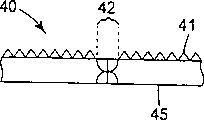
Fig. 2 is the cross-sectional side view of sleeve of expression one plumb joint thickness;
Fig. 3 is the cutaway view of traditional both sides plumb joint;
Thereby Fig. 4 is the cutaway view that had macro-energy to penetrate to cause the bandy rear side plumb joint of sleeve in welding process;
Fig. 5 is the cutaway view of the rear side plumb joint on butt joint type joint;
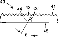
Fig. 6 is the cutaway view of the rear side plumb joint that has an angle on butt joint type joint;
Fig. 7 is the cutaway view of the rear side plumb joint on the lap jointing type joint;
Fig. 8 is the end of cutting sleeve before welding with an angle, then a welding material wedge is inserted the cutaway view of the formed rear side plumb joint of joint;
Fig. 9 is the cutaway view of nib welding;
Figure 10 is illustrated in and places a fin material on the molding side of instrument;
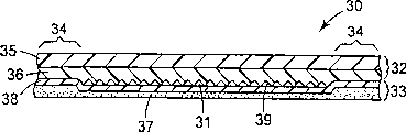
Figure 11 is the cutaway view of a reflecting piece;
Figure 12 a is the plane of a sleeve, wherein the axis of rotation of the relative sleeve of the sealing wire angle that tilts;
Figure 12 b illustrates the sleeve plane that sealing wire is a helix;
Figure 13 a to 13f shows instrument of the present invention, and wherein instrument comprises many instrument sheets that figure is arranged, and these instrument sheets combine, and forms closing line being parallel between each instrument sheet of the instrument ditch line of rabbet joint;
Figure 14 is according to the fiftyfold photo of the amplification of a closing line of the present invention;
Figure 15 is the fiftyfold photo of the amplification of traditional welding line;
Figure 16 is that the section according to the closing line in the instrument manufacture process of the present invention amplifies fiftyfold photo; And
Figure 17 is that the section of the traditional welding line in a conventional tool amplifies fiftyfold photo.
The specific embodiment
The invention provides a kind of have at least one figure (or molded) surface, be columnar instrument substantially, described surface is preferably by one and flat is originally drawn that the substrate carved or its duplicate forms.This instrument is preferably made like this, promptly from that surface soldered one plumb joint relative with at least one patterned surface, thereby forms a firm welding.The instrument that is made of like this at the closing line that produces a relative narrower from the reflecting piece of its manufacturing, is preferably had an appointment 0.0025 millimeter to about 0.2 millimeter width subsequently, and wherein this closing line produces the observer and has ornamental comfort.
Though the present invention narrates reflecting piece especially, also can be applicable to process other application scenario molded or that patterned surface is arranged.These application scenarios comprise the manufacturing of structurized abrasive product, as at U.S. Patent number 5,304,223 (people such as Pieper), U.S. Patent number 5,500,273 (people such as Holmes) and U.S. Patent number 5, several these series products of mentioning among 435,816 (people such as Spurgeon); Bonded product in the personal care product and mechanical fastener are for example at U.S. Patent number 4,973, described in 326 (people such as Miller), U.S. Patent number 5,312,387 (people such as Midgley) and the U.S. Patent number 5,679,302 (people such as Bychinski); Improve the brightness film, for example at U.S. Patent number 5,245, described in 454 (Blonder), U.S. Patent number 5,504,544 people such as () Dreyer and the U.S. Patent number 5,635,278 (Williams).
Fig. 1 is the schematic diagram of explanation technical process, partly shows the rotation mandrel (mandrel) 25 that a sleeve 27 is arranged on it.This sleeve is the illustrative shape of an instrument.Though will understanding easily, those skilled in the art are used for this sleeve is placed on many technology on the mandrel, but in one embodiment, be that heating one is columnar sleeve substantially and places it on the mandrel, in case after the cooling, sleeve just is contracted on this cylinder.Term " primary circle tubular " is meant an elongate hollow structure that wherein is formed with a cavity or open spaces and the cross section of selecting from shapes such as circle, ellipses is arranged.Perhaps, this sleeve can be fixed in cylinder with adhesive (for example organic bonding sticking, the scolder of thermosetting etc.) or with for example one or more pins of a mechanical device or one or more anchor clamps.According to the required purpose of the instrument of being produced, sleeve can have different sizes, and the multiple combination of sleeve diameter and bush material thickness can be arranged.
For example, in the manufacturing of reflecting sheet material, the diameter of sleeve is preferably between about 20 to 130 centimetres.But the common skilled person of this area knows that according to the size of process equipment (for example welding machine and/or molding apparatus), the diameter of sleeve can be a virtually any size.Though as long as material can form a primary circle tubular and just can use any thickness, the thickness of bush material can be between about 0.25 to 2.5 millimeter, preferably between about 0.4 to 1.0 millimeter.
In the process that forms sleeve, one embodiment comprises in such a way this instrument is rolled into a cylinder, promptly, cause the both ends that do not need basically firmly instrument to keep together, just in instrument, be not tending towards elasticity and separate both ends its residual force of getting back to the original plane state is existed.Utilize a rolling and processing can finish this requirement, wherein use an equipment usually, this equipment in a step generally under the high pressure effect roll extrusion and/or bending go out one one-tenth columnar complete curve.The example that is used for the suitable equipment of rolling and processing is the product that can be called ONE-PASSROLL BENDING MACHINE (once by the roll extrusion bending machine) from the commodity that the Acrotech company in Minnesotan Lake city buys.This clamping device that can keep together with the two ends with instrument is finished.The example of clamping device is that (1) copper anchor clamps, (2) magnetic sheet apply vacuum with (3).
Instrument has a molded surface, i.e. a patterned surface, and this surface has many its shape and size to be suitable for forming the dentalation of required reflecting unit (for example indenture) usually.In this instrument, at the opening at each indenture top surface place base portion corresponding to the reflecting unit that is generated.Suitable indenture and the reflecting unit that generates like this can be that pyramid three sides, that include a cube corner is arranged, as at U.S. Patent number 4,588, that is disclosed among 258 (Hoopman) is such, one rectangular base and two rectangle sides and two triangle sides perhaps can be arranged, and each unit just all includes two cube corners like this, as at U.S. Patent number 4, disclosed among 938,563 people such as () Nelson like that.And each indenture all has one corresponding to the back degree of depth to the reflecting unit height that is generated.For example, each indenture can have the degree of depth (therefore producing reflecting unit of this height) of 0.06 millimeter, 0.09 millimeter and 0.18 millimeter.But those skilled in the art will readily appreciate that according to the many indentures of the present invention in this instrument Any shape to be arranged, and a certain given instrument can comprise many indenture shape and size.Person skilled in the art also will readily appreciate that, can replace indenture or increase ledge except indenture with ledge.
In the process that forms many reflecting units, usually flowable resin is put on the molded surface of instrument, i.e. patterned surface.Resin should be with respect to molded surface mobile (for example entering in each die cavity of molded surface) when selectively using vacuum, pressurization or mechanical device.For pitted mould, preferably use the resin of sufficient amount, it fills up numerous indentures at least substantially.For the mould that reverse figure is arranged (for example making the needed ledge of sheet material described in the U.S. Patent number 09/227,963 that awaits the reply jointly), preferably apply the resin of q.s, it covers all ledges substantially and is suitable for tool surfaces.The resin that selection is used for the cube corner cell array preferably can produce the product that efficient retroreflection (reflective) and fully durable and against weather can be provided.Suitably the illustrative example of polymer for example comprises acrylic resin, Merlon, polyester, polyethylene, polyurethane, cellulose acetate butyrate polymer and chlorine vinyl chloride.
In many cases, wish to utilize the first generation of a mould or patterned surface or after a while the duplicate of several generations as instrument.According to the character of employed instrument and resinous principle, after the curing, a plurality of one-tenth figure reflecting units just can or can need separation (pating) layer to obtain required stalling characteristic from the instrument separation.The illustrative example of separating layer material comprises that one causes the combination of surface oxide layer, an intermediate thin metal coating, chemical silvering, different materials or coating.If desired, suitable preparation can be introduced resinous principle, use the required stalling characteristic of acquisition behind resin solidification.
The instrument that is used to duplicate reflecting unit is formed on the flat substantially plane of a matrix material usually, and matrix material is suitable for processing with the following direct machining technique that limits.Especially preferable material is that those can not form burr, low ductility and low graininess and those materials that keep dimensional accuracy after shaping surface are arranged machined.Because metal can form required shape and fabulous optical surface is provided, so that resulting reflecting unit structure is back to reflective function the best, so metal is a preferable baseplate material.Also can utilize various machinable plastics (comprising thermosetting and thermoplastic), for example acrylic resin.
" directly machined " technology is also referred to as " draw and carve " usually, and it comprises the cutting tip substrate, produces the indenture or the groove figure that intersect, comprises the structure cube corner unit, that form final reflecting unit thereby form.Directly machining technique is suitable for making the master mold of little cube of little array.Little cube of little array is particularly advantageous for the thin array that duplicates that production has the flexibility improved.Little cube of array also is useful for continuous processing and manufacturing.The processing of making little cube of big array trends towards using direct machine-tooled method, rather than other technology.At U.S. Patent number 4,588, disclosed a direct mach illustrative example among 258 (Hoopman).
Directly machining process formation one comprises flat " being delineated master mold " part (or " instrument sheet ") of required figure.Because the instrument sheet tool sizes than required usually is little, so the edge of each instrument sheet of machined makes it that certain size be arranged.Assemble these instrument sheets then and become a composite tool.In the past, assemble these instrument sheets with the seam of the bonding every instrument sheet of common adhesive.The common skilled person of this area will be understood that the dimension of picture on the instrument sheet is depended in the measure of assembling tool sheet.For example, when figure comprises less relatively cube of figure, because found that closing line is tending towards more remarkable in by the little cube of formed reflecting piece of figure, so special seam (being also referred to as closing line) of wishing that formation is less.
These closing lines between the instrument sheet are preferably less than 0.0025 millimeter, and are difficult to find them by naked eyes in flat substrate in batch piece installing.Can utilize these assemblies that image substrate is arranged as a master mold, can form a series of impressions, i.e. duplicate from this master mold.In some cases, master mold itself can be used as a back to reflective article.But duplicate comprises the duplicate in many generations, is used as the back more at large to reflective article.When instrument has required size, as shown in Figure 2 it is wound into sleeve 40 with a patterned surface 41 and a trailing flank 45.Sleeve 40 be preferably make its opposite end 43 and 43 ' mutually very close to so that they can for good and all engage.
Fig. 3 shows the cross section of traditional welding line 42, and the end of its middle sleeve relies on a banjo fixing butt jointing of formation usually and combines, and welds on front side (the figure side is promptly arranged) and rear side then.Usually the width that is formed on the sealing wire on the figure side of instrument is about 0.5 to 1.0 millimeter.This sealing wire can produce a seam mould that is generated or goods (for example reflecting piece of duplicating from it).In the reflecting piece of being produced by this instrument, the visibility of this seam under daylight and back reflected laser surpasses the degree of wishing.The grain surface of this seam causes catoptrical scattering and makes seam more obvious.If reflecting piece is by the instrument manufacturing that has metal coating on it, especially like this.And flowable resin can adhere to sealing wire, forms fault in the reflecting piece of making.In addition, the physical distortions that is adjacent to the figure of sealing wire can produce a reflecting piece that comprises undesirable optical gradient.
Fig. 4 shows one and is intended to usually weld the sealing wire 42 that (particularly by superlaser) produced from rear side.It is outwardly-bent that this instrument trends towards leaving the sleeve center.Therefore, except producing unsuitable wide sealing wire, the distortion of tool shape also can cause the fault of reflecting piece.
Fig. 5 to 10 and 12a and 12b cut into a target shape according to the present invention with the opposite end of instrument, to remedy the example of the problems referred to above.In Fig. 5, show a butt joint type joint, it has a rear side that forms closing line 44 welds, and can be used as the representative of one embodiment of the invention.According to the present invention, utilize a welding machine opposite end is bonded together and forms a closing line 44 from the rear side of instrument.
Though the welding machine of many types is deemed appropriate, a preferable welding machine is a laser welder.Usually laser welder has four types: the carbon dioxide laser that utilizes helium, nitrogen and carbon dioxide mixture; Utilization has the ruby laser of the synthetic ruby of chromium in aluminium dioxide; The neodymium of the neodymium of utilization in glass: amorphous laser; And the neodymium that utilizes the garnet crystal of yttrium, aluminium and doping neodymium: YAG laser.The laser welder that is fit to of Yttrium aluminium garnet (YAG) type can be buied from the HDESystems Co., Ltd in California Sunnyvale city or from the LMI company in state of Wisconsin Somerset city.
Preferably, laser instrument is installed on the support that is small enough to be installed in the sleeve diameter.Parameter crucial in welding processing is the feed speed of (1) laser beam along weld line, and unit is per minute cms (centimeters/minute); (2) impulse speed (PPS) in the per second; And the energy of (3) each pulse.These parameters have determined the percentage of the penetration depth of the spot size of each pulse and welding.Preferably above welding parameter is set for when 100% such penetration depth that when rear side welds, can't reach instrument thickness.Occur from the patterned surface side of instrument, in sealing wire or near it or during ejection, can regard one of percentage hundred penetration depths as the blister of deposite metal.Though these blisters can grind off, the welding modified line becomes unacceptable wide.Find that preferable maximum penetration is about 90%, a welding that makes the shrink-fit of sleeve on cylinder subsequently have required sufficient intensity so just can be provided, make the active force on the adjacent domain on the figure side of the width of joint and instrument keep minimum simultaneously.And, be preferably and when reaching this welding penetration depth, make the energy of each pulse remain on a minimum of a value.
When the figure side of instrument is observed, the closing line width that the present invention produced is usually from about 0.0025 millimeter to about 0.2 millimeter.Though surpass size or optical property that this width can influence cube corner, the closing line of reflecting piece color and outward appearance by day remains unchanged in this width, and produces pleasant improvement in aesthetic.When near this closing line of inspection, it demonstrates a series of single pad corresponding to the laser incidence point.All spacings along closing line umber of pulse of the per second by regulating laser are usually regulated, and preferably these points are overlapped.When too low or feed speed is too high when the umber of pulse of per second, welding become discontinuous and a little less than.Mainly weld the percentage of penetration depth by the requirement of strength decision.This numeral depends on the quality of the thickness and the welding machine of material, instrument.Wish that welding penetration depth percentage is lower, so that to the damage minimum of the cube corner on the molded surface of instrument.
As mentioned above, other parameter also influences the closing line of generation.For example, the laser machine is that about 2.5 centimeters/minute are to 1600 centimeters/minute along the preferable feed speed of closing line.One preferable impulse speed is that about 5PPS is to about 100PPS.The preferable energy of each pulse is about 20 Jiao Er or littler.Though provided preferred range for welding nickel, those skilled in the art are on the basis of disclosed content, can easily determine the setting value of above-mentioned parameter, thereby according to instruction of the present invention, to the percentage of the suitable welding penetration depth of other material production one.
A formed closing line 44 when Fig. 6 shows the thickness that end (43 and 43 ') when instrument crosses instrument and is an angle θ and is cut with the radius of relative sleeve.Utilize this embodiment to avoid the heating of the direct arrival molded surface that produced from the rear side welding processing and avoid damaging all cubes.
Fig. 7 shows lap jointing type closing line 44.The benefit of this closing line also comprises the mechanical interlocked bond strength that increased except from the effect of rear side welding.
Fig. 8 shows how to form a wedge joint 46, and wherein the opposite end 43 and 43 of cutting element ' be cut becomes to stay an open wedge 50, and forms trapezoidal bottom on rear side.As an example, a nickel system instrument cutting is become such shape, and the nickel system wedge 51 of this approximate open area is inserted in the opening of instrument.Weld from rear side then, obtain the welding of suitable intensity, simultaneously to the damage minimum of the molded surface of instrument.
Fig. 9 shows outstanding edge connector.Preferably remove the cube corner unit, so that the damage minimum of cube-corner from welding region 53.When watering resin in the instrument, just produced the nib that is fit to be adhered to a sealing film.It should be noted that, can be in molded surface with the pattern cut of all indentures, providing support the edge of sealing film, and avoid occurring the outward appearance of any closing line.
Figure 10 shows the fin 60 on the molded surface 41 of the instrument of being placed on 40, and it makes the temperature of graphic element minimum, thereby reduces physics and distortion optics of the width of molded surface 41 and closing line 44.Any highly heat-conductive material all is fit to, and wherein copper is preferable.In addition, cooling agent can be drawn fin material, with further reduction surface temperature.
Figure 11 shows a kind of cut-away view of porous sheet 30, and this plate has surface element 32, a basic component 33 of a substantially transparent and keeps surface element is that supporting separately seals leg member 34 to basic component.Surface element, basic component and sealing leg member form the stingy chamber 31 of many sealings.The part that forms all little air chambers is called hermetic unit.Each is stingy indoor as being included in to reflecting component 39 behind the individual layer of cube corner, thereby all cube corners have an air interface.An example of porous sheet is the top grade sheet material that can be called SCOTCHLITE DIAMOND GRADE from 960 series, white, the commodity that the 3M company in Minnesota State Borrow city buys.Find the back to reflective and narration reflecting piece from ASTM (American Standard Testing Manual) D4956-94 (in November, 1994) " the standard technique specification that is used for the reflecting piece of traffic control ".At U.S. Patent number 5,138,488 (Szczech), 5,450,235 (Smith), 5,614,286 (Bacon), 5,706,132 (people such as Nestegard), 5,714,233 (people such as Araki) and 5, some illustrative examples have also been disclosed among 754,338 (people such as Wilson) based on the reflecting piece of cube corner.
Surface element 32 preferably includes an overlapping film 35 and a body part 36.Body part comprises for example single layer of cube corner of all reflecting units 39.But a common boundary layer (land layer) is present between the individual layer of overlapping layer and all cube corners as the part of body part.Surface element 32 can be a homogenous material, but comprises the several layers of different materials usually.Be preferably dimensionally stable, durable, against weather and be configured as the material of desired structure easily for the selected material of surface element.For example can from the vinyl halide fluidized polymer of fluorinated polymer, the ethylene copolymer that contains ionic bond, low density polyethylene (LDPE), plasticising, polyethylene and ethylene copolymers and aliphatic series and polyurethane material aromatics, select optical superposition film 35.The thickness of overlapping film is usually between about 0.01 to 0.2 millimeter.The thickness of boundary layer preferably wishes to have the minimum thickness near zero millimeter usually less than 0.25 millimeter.The polymeric material that selection is used for body part 36 be thermoplastic be the harder rigid material that relative other polymer has higher Vicat (dimension card) softening temperature with being tending towards.It is traditional using term " thermoplastic " here, means when being heated the material that softens, gets back to its original state when catching a cold again substantially.The examples of material that is suitable for body part comprises polyacrylic polymer, acrylic resin, PC, polyimides and their mixture.
Basic component 33 also can be described as backing sheet or sealing film.Basic component 33 has first side 38 and one second side that contacts with air or sealing shank, and second side has its adhesive that is provided with a liner (not shown) 37 usually.Basic component is arranged on after the individual layer cube corner unit, is used for keeping space on every side, many cube corners unit.Preferably this basic component comprises a thermoplastic.As the preferable polymer of basic component is as U.S. Patent number 5,754, among the styrene family of the multiphase copolymer resin described in 338 people such as () Wilson.The vicat softening temperature of basic component is usually less than about 30 ℃ of the softening temperature of the body part of surface element.The thickness of basic component is usually between about 0.01 to 0.25 millimeter.
Individual layer cube corner unit also can be described as prism, little prism or triple mirror.The height of cube corner unit is usually between about 0.02 to 0.5 millimeter.Among the molded body part that enters surface element of this microstructured layers.
The sealing leg member also can be described as abutment wall, bonding part or barrier film.As U.S. Patent number 4,025, suggested among 1 59 (McGrath), usually to surface element and basic component heating and pressurization formation sealing leg member.
Sometimes, the ledge on the mold pressing roll is aimed at closing line and produce a transparent thread in the sealing leg member.Can utilize the inclination of closing line 44 as shown in Figure 12 to solve this problem.As shown in Figure 12 a, suitable angle is approximately 2.5 degree, but any angle that can reduce the degree of registration of this ledge and closing line all is useful.
Figure 12 b is an example that changes the design of Figure 12 a, and wherein closing line 44 has a helix shape of the width that crosses this sheet material.As mentioned above, this shape also can be avoided the aliging of ledge on closing line and the mold pressing roll.Person skilled in the art will be understood that the many target shapes that can finish this purpose are arranged within the scope of the invention.
In a preferred embodiment of the present invention, design cavity or profile that one or more closing line is parallel to this tool profile.In better embodiment, closing line also will not be the straight line that crosses belt or roller.Therefore, any duplicating of closing line will can not be parallel to an application station or mould lip in this plate.This feature helps avoid the unstability that flows in coating processing, and allows to increase coating speed.When closing line is the inclination of oblique line shape, require long welding.These long welding preferably help to finish higher following thin slice (down-web) intensity, distributed stress, and " take paulin (tenting) " when instrument causes less instrument during bending on a radius.
As previously discussed, the process that scales up that is used for these instruments often requires figure to be bonded into a thin slice that is extended.Require accurate sheet that sheet is assembled, but may be difficult to finish this work.In the described embodiment of Figure 13 a-13f, the edge of the master mold by making finishing is parallel to the ditch line of rabbet joint of instrument, can finish assembling easily.Equally, in when assembling, master mold forms has a belt that is parallel to the closing line of the ditch line of rabbet joint.
Figure 13 a shows and how to cut a series of ditch line of rabbet joint (52,54,56) and to form a master mold figure 50 at an in-plane.All cube corners position is not shown in Figure 13 a, but will will be ledge in each complete triangle 58 inside that illustrates.Person skilled in the art are appreciated that and can be used to provide the thin slice with different optical corner angle and/or other reflective characteristic (for example improving the viewing angle performance) by the orientation of the various angular turn ditch line of rabbet joint.
Figure 13 b shows the master mold 60 after whole fluted finishings.Figure 13 c and 13d show the master mold (70+80) after the other finishing, are used as the avris part of magnify tool in proportion.
Can (i) as shown in Figure 13 e or 13f, the end that the master mold (60,70 and 80) after the finishing is combined and (ii) will combine welds and forms a reel, just can produce a finished product instrument.As shown in the figure, the joint line of Figure 13 e and Figure 13 f is parallel to the groove of instrument.It will be understood that for a certain instrument, in conjunction with the quantity of master mold decide by the size of master mold and the required size of finished product instrument.Except shown in rhombus and the triangle master mold, according to principle of the present invention, can utilize other shape.
Tool device shown in Figure 13 a-f also is fit to utilize the solder technology in this narration.Preferably, weld together from the cavity side of cylinder end these instruments.But the instrument shown in Figure 13 a-f also can connect from the non-NULL face down bonding, and other advantage described herein still can be provided.And the described instrument sheet of Figure 13 a to 13f method can be used for assembling with the nonmetallic materials instrument made of plastics (for example Merlon, polyester, acrylic resin etc.) for example.These instruments still can provide the significant advantage and the benefit of the groove that closing line is parallel to instrument.
Example
Now will be in conjunction with only being that illustrative some example is described the present invention.
The employed material nickel of formation instrument (can buy its particle shape product from the INCO company of Britain), this material of electroforming, formation thickness are 0.4 millimeter smooth substantially instrument.
A flat substrate that utilizes rolling technology will have a patterned surface and the rear surface relative with this patterned surface forms a cylinder, wherein flat substrate is installed on the roll unit, this roll unit is a product that can buy from the Acrotech company of Minnesota State Lake, commodity ONE-PASS roll BENDINGMACHINE by name.
Then cylindrical sleeve is placed on the cylinder and utilizes a mechanical clamp to remain on the appropriate location.One laser-welding machine (can be the product of LUMONICS JK 702 from the commodity that the Laser Processing company in state of Wisconsin Somerst city buys) is placed on the center of cylindrical sleeve.Regulate this laser instrument by following parameter: laser instrument is 63.5 centimeters/minute along the feed speed of cylinder inboard, and pulse rate is that the energy of 45 pulses of per second and each pulse is each pulse 6 Jiao Er.
Figure 14 is that an aforesaid closing line amplifies fiftyfold photo.The width of having measured this closing line is 0.008 millimeter.As a comparison, Figure 15 is that a traditional welding line amplifies fiftyfold photo.The width of having measured this weld line is 0.7 millimeter.Also noticed in this instrument sealing wire near patterned surface distortion is arranged.
Figure 16 is that fiftyfold photo is amplified in the cross section of the closing line in the instrument made in accordance with the present invention.Shown in Fig. 16, through welding processing, near the figure the closing line is kept perfectly substantially.As a comparison, Figure 17 is that fiftyfold photo is amplified in the cross section of the traditional welding line in a conventional tool.As shown in the figure, the sealing wire in the conventional tool has moderate finite deformation at rear side and figure side.
Should be appreciated that, be illustrative and nonrestrictive with above-mentioned chatting.Without departing from the scope of the invention, according to above narrating content, various modifications and variations of the present invention will be conspicuous for those skilled in the art, should be appreciated that, the present invention is not restricted to the embodiment shown in above.
Claims (22)
1. the method for a fabrication tool, it comprises the following steps:
Provide one to be the instrument on plane substantially, it has relative first end and second end, a figure side and a rear side relative with the figure side mutually;
Two opposite ends are put together the primary circle tubular that formation wherein has a cavity, and wherein trailing flank is facing to cavity; It is characterized in that,
Weld described two ends from inner chamber, two opposite ends of rear side are bonded together;
On the figure side, provide width to arrive about 0.2 a millimeter closing line for about 0.0025 millimeter.
2. according to the method for claim 1, it is characterized in that the step that both ends are welded together comprises: from cavity that two ends are welded together, formed welding penetration depth is less than 100%.
3. according to the method for claim 1, it is characterized in that, also comprise the following steps: to utilize from mechanical clamp, magnetic sheet or use that selected fastener keeps together two opposite ends this group of vacuum.
4. according to the method for claim 1, it is characterized in that described primary circle tubular has one to be the cross section of circle substantially.
5. according to the method for claim 1, it is characterized in that this instrument comprises more than one instrument section, so that this instrument comprises the about 0.0025 millimeter closing line to about 0.2 millimeter one or more of width in the figure side.
6. according to the method for claim 1, it is characterized in that described instrument comprises a metal.
7. according to the method for claim 6, it is characterized in that described metal is to select from formed one group of aluminium, brass, copper, nickel and their combination.
8. according to the method for claim 1, it is characterized in that the step of welding two opposite ends comprises: the rear side of instrument is exposed to from carbon dioxide laser, ruby laser, neodymium: amorphous laser and neodymium: the laser instrument of selecting a group of yttroalumite pomegranate laser instrument.
9. according to the method for claim 1, it is characterized in that the step that two opposite ends are welded together comprises: it is the laser instruments of about 2.5 centimeters/minute to about 1600 centimeters/minute that the rear side of this instrument is exposed to feed speed.
10. according to the method for claim 1, it is characterized in that the step that two opposite ends are welded together comprises: the rear side of this instrument is exposed to pulse rate is 5 pulses of about per second laser instruments of 100 pulses of about per second extremely.
11. the method according to claim 1 is characterized in that, the step that two opposite ends are welded together comprises: about 20 Jiao Er of energy or the littler laser instrument that the rear side of this instrument are exposed to each pulse at least.
12. the method according to claim 1 is characterized in that, after two opposite ends are put together, a fin is placed near the figure side.
13. the method according to claim 1 is characterized in that, the step that two opposite ends are put together produces the joint of selecting from banjo fixing butt jointing, welding point, lap joint or nib joint one group.
14. the method according to claim 1 is characterized in that, the figure side of this flat tool comprises many reflecting units in an array, and two abutting ends of instrument form a closing line that is parallel to all reflecting unit arrays.
15. the method according to claim 1 is characterized in that, provides the step of a basic flat tool to comprise the step of assembling polylith instrument sheet, thereby forms all closing lines between the adjacent tool sheet.
16. the method according to claim 15 is characterized in that, all instrument sheets comprise all rhombuses and the leg-of-mutton instrument sheet of a plurality of microstructure units that have in an array, and the closing line between the adjacent tool sheet is parallel to the array of all microstructure units.
17. a mould that is used to make the goods with a patterned surface, this mould comprises: one has outer surface, an inner surface and a closing line of figure, it is characterized in that, be included on the figure side width and be about 0.0025 millimeter to about 0.2 a millimeter closing line.
18. mould as claimed in claim 17 is characterized in that, the welding penetration depth of described closing line is less than about 100% instrument thickness.
19. micro-structural composite sheet of making by the described mould of claim 17, it comprises: the cubical array of cube microstructure unit that forms with a polymeric material wherein is present in about 0.0025 millimeter to about 0.2 millimeter of the width of any suture in this array in the figure side.
20. the method for a fabrication tool, it comprises the following steps:
By assembling polylith instrument sheet, the instrument on one basic plane is provided, this instrument has the figure side and a rear side relative with the figure side that the first mutually relative end and second end, comprise all microstructure unit arrays, thereby form all closing lines between the adjacent tool sheet, wherein all closing lines between the adjacent tool sheet are parallel to the array of microstructure unit;
Two opposite ends are put together the primary circle tubular that formation wherein has a cavity, and wherein trailing flank is facing to cavity; Two ends are bonded together, engage two opposite ends of rear side at least; It is characterized in that,
The step of described joint comprises from described cavity both ends is welded together.
21. the method according to claim 20 is characterized in that, instrument comprises a plastic sheet.
22. the method according to claim 21 is characterized in that, the step of joint comprises the both ends with thermal weld or the bonding described plastic sheet of adhesive.
Applications Claiming Priority (4)
| Application Number | Priority Date | Filing Date | Title |
|---|---|---|---|
| US14810498A | 1998-09-04 | 1998-09-04 | |
| US09/148,104 | 1998-09-04 | ||
| US09/379,398 | 1999-08-24 | ||
| US09/379,398 US6322652B1 (en) | 1998-09-04 | 1999-08-24 | Method of making a patterned surface articles |
Publications (2)
| Publication Number | Publication Date |
|---|---|
| CN1316945A CN1316945A (en) | 2001-10-10 |
| CN1118360C true CN1118360C (en) | 2003-08-20 |
Family
ID=26845525
Family Applications (1)
| Application Number | Title | Priority Date | Filing Date |
|---|---|---|---|
| CN99810583A Expired - Fee Related CN1118360C (en) | 1998-09-04 | 1999-08-27 | Method of making mold for patterned surface articles |
Country Status (8)
| Country | Link |
|---|---|
| US (4) | US6322652B1 (en) |
| EP (1) | EP1117517A1 (en) |
| JP (1) | JP2002524298A (en) |
| KR (1) | KR100627081B1 (en) |
| CN (1) | CN1118360C (en) |
| AU (1) | AU6023199A (en) |
| CA (1) | CA2340453A1 (en) |
| WO (1) | WO2000013873A1 (en) |
Cited By (1)
| Publication number | Priority date | Publication date | Assignee | Title |
|---|---|---|---|---|
| CN110065249A (en) * | 2014-11-20 | 2019-07-30 | 艾利丹尼森公司 | The method that manufacture splice product and manufacture form the mold of Retroflective article |
Families Citing this family (50)
| Publication number | Priority date | Publication date | Assignee | Title |
|---|---|---|---|---|
| US6322652B1 (en) * | 1998-09-04 | 2001-11-27 | 3M Innovative Properties Company | Method of making a patterned surface articles |
| EP1211992B1 (en) * | 1999-09-13 | 2004-01-14 | Synthes AG Chur | Bone plate system |
| US6908295B2 (en) * | 2000-06-16 | 2005-06-21 | Avery Dennison Corporation | Process and apparatus for embossing precise microstructures and embossing tool for making same |
| US6508558B1 (en) * | 2000-10-02 | 2003-01-21 | Printmark Industries, Inc. | Retroflective prismatic retro-reflectors without visually disturbing seams |
| US6644818B2 (en) * | 2000-10-02 | 2003-11-11 | Printmark Industries, Inc. | Retroreflective prismatic retro-reflectors without visually disturbing seams |
| DE10049283A1 (en) * | 2000-10-05 | 2002-04-11 | Hueck Folien Gmbh & Co Kg | Method and device for producing a cylindrical embossing mold |
| US6931665B2 (en) * | 2001-07-30 | 2005-08-23 | 3M Innovative Properties Company | Vapor permeable retroreflective garment |
| JP4413491B2 (en) * | 2002-12-11 | 2010-02-10 | 矢崎総業株式会社 | How to connect wires and connection terminals |
| US7174619B2 (en) | 2003-03-06 | 2007-02-13 | 3M Innovative Properties Company | Methods of making microstructured lamina and apparatus |
| US7410604B2 (en) * | 2003-03-06 | 2008-08-12 | 3M Innovative Properties Company | Method of making retroreflective sheeting and slot die apparatus |
| US6884371B2 (en) * | 2003-03-06 | 2005-04-26 | 3M Innovative Properties Company | Method of making retroreflective sheeting and articles |
| US9307648B2 (en) | 2004-01-21 | 2016-04-05 | Microcontinuum, Inc. | Roll-to-roll patterning of transparent and metallic layers |
| US20060128852A1 (en) * | 2004-12-13 | 2006-06-15 | General Electric Company | Compositions for articles comprising replicated microstructures |
| US20060128853A1 (en) * | 2004-12-13 | 2006-06-15 | General Electric Company | Compositions for articles comprising replicated microstructures |
| GB0427607D0 (en) * | 2004-12-16 | 2005-01-19 | Microsharp Corp Ltd | Structured optical film |
| JP4951873B2 (en) * | 2005-04-14 | 2012-06-13 | 大日本印刷株式会社 | Method for producing relief formed body |
| KR101341606B1 (en) * | 2005-09-21 | 2013-12-13 | 오리엔트 가가쿠 고교 가부시키가이샤 | Laser welded product |
| CA2643510C (en) * | 2006-02-27 | 2014-04-29 | Microcontinuum, Inc. | Formation of pattern replicating tools |
| US7963827B2 (en) * | 2006-07-14 | 2011-06-21 | Saint-Gobain Abrastives, Inc. | Backingless abrasive article |
| US8940117B2 (en) | 2007-02-27 | 2015-01-27 | Microcontinuum, Inc. | Methods and systems for forming flexible multilayer structures |
| US8179034B2 (en) | 2007-07-13 | 2012-05-15 | 3M Innovative Properties Company | Light extraction film for organic light emitting diode display and lighting devices |
| US20090015142A1 (en) | 2007-07-13 | 2009-01-15 | 3M Innovative Properties Company | Light extraction film for organic light emitting diode display devices |
| KR101664124B1 (en) * | 2007-09-05 | 2016-10-10 | 알바니 인터내셔널 코포레이션 | Process for producing papermaker's and industrial fabric seam and seam produced by that method |
| WO2009042118A1 (en) * | 2007-09-24 | 2009-04-02 | Reflexite Corporation | Retroreflective structure with fabric face |
| KR100918191B1 (en) | 2007-10-12 | 2009-09-22 | 미래나노텍(주) | A pattern formed sheet, a forming mold and apparatus for manufacturing an the sheet |
| KR20100091215A (en) * | 2007-11-19 | 2010-08-18 | 쓰리엠 이노베이티브 프로퍼티즈 컴파니 | Articles and methods of making articles having a concavity or convexity |
| CN101456667B (en) * | 2007-12-10 | 2011-12-21 | 鸿富锦精密工业(深圳)有限公司 | Prismatic lens producing method |
| JP5140499B2 (en) * | 2008-06-25 | 2013-02-06 | 東芝機械株式会社 | Transfer roll and transfer device |
| US7957621B2 (en) | 2008-12-17 | 2011-06-07 | 3M Innovative Properties Company | Light extraction film with nanoparticle coatings |
| WO2010080378A1 (en) | 2008-12-19 | 2010-07-15 | 3M Innovative Properties Company | Method and system for fabricating nanostructure mass replication tool |
| USD665584S1 (en) * | 2010-03-05 | 2012-08-21 | Orafol Europe Gmbh | Retro-reflective sheeting with a corner cube surface pattern having angular corner cube circular regions |
| US8845912B2 (en) | 2010-11-22 | 2014-09-30 | Microcontinuum, Inc. | Tools and methods for forming semi-transparent patterning masks |
| CN103998972B (en) * | 2011-10-17 | 2017-06-09 | 斯坦雷电气株式会社 | Reflector array optical device and its manufacture method |
| JP2013097286A (en) * | 2011-11-04 | 2013-05-20 | Asahi Kasei E-Materials Corp | Cylindrical mold |
| US20130193597A1 (en) * | 2012-02-01 | 2013-08-01 | Reflexite Corporation | Reflector molding apparatuses and methods thereof |
| JP5687232B2 (en) * | 2012-03-08 | 2015-03-18 | 旭化成イーマテリアルズ株式会社 | Transfer device |
| US9050762B2 (en) | 2012-03-23 | 2015-06-09 | Orafol Americas Inc. | Methods for fabricating retroreflector tooling and retroreflective microstructures and devices thereof |
| WO2013151691A1 (en) * | 2012-04-06 | 2013-10-10 | 3M Innovative Properties Company | Tools for making retroreflective articles |
| EP2687318B1 (en) | 2012-07-18 | 2015-01-14 | Emerson Climate Technologies GmbH | Method of joining two components together by means of a welding process using an intermediate parts |
| US20140093692A1 (en) * | 2012-09-28 | 2014-04-03 | Soken Chemical & Engineering Co., Ltd. | Resin Mold, Production Process Therefor and Uses Thereof |
| US9815230B2 (en) | 2012-11-22 | 2017-11-14 | Soken Chemical & Engineering Co., Ltd. | Imprint mold manufacturing method, imprint mold, and imprint mold manufacturing kit |
| ES2410655B1 (en) * | 2013-04-08 | 2014-01-30 | Jesús PÉREZ GÓMEZ | Sanitary elements manufacturing procedure |
| US9589797B2 (en) | 2013-05-17 | 2017-03-07 | Microcontinuum, Inc. | Tools and methods for producing nanoantenna electronic devices |
| JP2016539011A (en) * | 2013-10-18 | 2016-12-15 | スリーエム イノベイティブ プロパティズ カンパニー | Coated abrasive article and method for producing the same |
| JP6271319B2 (en) * | 2014-03-28 | 2018-01-31 | 株式会社総合車両製作所 | Laser welding method |
| JP2018501981A (en) * | 2014-12-10 | 2018-01-25 | ザ・チャールズ・スターク・ドレイパー・ラボラトリー・インコーポレイテッド | Polymer micro wedge and method of manufacturing the same |
| US9817163B2 (en) | 2015-04-15 | 2017-11-14 | Avery Dennison Corporation | Vented tooling belt for production of structured surfaces |
| TW201718228A (en) * | 2015-09-17 | 2017-06-01 | Soken Chemical & Engineering Co Ltd | Method for manufacturing mold for imprinting |
| IL270791B2 (en) | 2017-05-25 | 2023-10-01 | Magic Leap Inc | Double-sided imprinting |
| GB2580822B (en) | 2017-09-11 | 2022-07-13 | Orafol Americas Inc | Methods of fabricating retroreflector prisms with polygonal apertures and devices thereof |
Family Cites Families (45)
| Publication number | Priority date | Publication date | Assignee | Title |
|---|---|---|---|---|
| US3207644A (en) * | 1959-07-20 | 1965-09-21 | Garlock Inc | Method of making a fluorocarbon resin jacketed gasket |
| US3454442A (en) * | 1965-10-19 | 1969-07-08 | Heller William C Jun | Art of thermally joining materials |
| US3689346A (en) | 1970-09-29 | 1972-09-05 | Rowland Dev Corp | Method for producing retroreflective material |
| US3791020A (en) * | 1971-09-07 | 1974-02-12 | Torrance Machinery & Eng | Inverted tube mill method |
| US4000392A (en) * | 1974-07-01 | 1976-12-28 | United Technologies Corporation | Fusion zone purification by controlled laser welding |
| JPS5922289B2 (en) * | 1975-11-20 | 1984-05-25 | ソニー株式会社 | How to get started |
| CA1046801A (en) * | 1975-12-10 | 1979-01-23 | Edward G. Spisak | Welding machine |
| US4025159A (en) | 1976-02-17 | 1977-05-24 | Minnesota Mining And Manufacturing Company | Cellular retroreflective sheeting |
| US4202600A (en) * | 1978-04-24 | 1980-05-13 | Avery International Corporation | Diced retroreflective sheeting |
| US4155693A (en) * | 1978-07-24 | 1979-05-22 | Ethyl Corporation | Embossed screen assembly |
| JPS58128287A (en) * | 1982-01-27 | 1983-07-30 | Fujikura Ltd | Formation of seam welded zone of metallic pipe containing wire rod |
| US4478769A (en) | 1982-09-30 | 1984-10-23 | Amerace Corporation | Method for forming an embossing tool with an optically precise pattern |
| US4588258A (en) | 1983-09-12 | 1986-05-13 | Minnesota Mining And Manufacturing Company | Cube-corner retroreflective articles having wide angularity in multiple viewing planes |
| DE3405985C2 (en) | 1983-09-14 | 1986-01-16 | J.H. Benecke Gmbh, 3000 Hannover | Process for the production of an embossing roller for the continuous embossing of the surface of a thermoplastic film with a grain |
| US4577088A (en) | 1984-06-27 | 1986-03-18 | Sws Inc. | Method of laser butt welding |
| US4751777A (en) | 1986-09-02 | 1988-06-21 | Jpi Aquisition, Inc. | Method for making a full round bushing |
| US4938563A (en) | 1986-11-21 | 1990-07-03 | Minnesota Mining And Manufacturing Company | High efficiency cube corner retroflective material |
| DE3713527A1 (en) | 1987-04-22 | 1988-11-10 | Bernd Buedenbender | WELD |
| FR2619336B1 (en) | 1987-08-13 | 1989-12-01 | Marechal Ets | PROCESS FOR THE PRODUCTION OF A HOT-GRAINING CYLINDER OF THERMOPLASTIC SHEETS |
| US4973326A (en) | 1987-11-30 | 1990-11-27 | Minnesota Mining And Manufacturing Company | Disposable diaper with improved fastener attachment |
| US5138488A (en) | 1990-09-10 | 1992-08-11 | Minnesota Mining And Manufacturing Company | Retroreflective material with improved angularity |
| US5679302A (en) | 1990-09-21 | 1997-10-21 | Minnesota Mining And Manufacturing Company | Method for making a mushroom-type hook strip for a mechanical fastener |
| US5152917B1 (en) | 1991-02-06 | 1998-01-13 | Minnesota Mining & Mfg | Structured abrasive article |
| JP2967239B2 (en) * | 1991-02-14 | 1999-10-25 | 日本ステンレス工材株式会社 | Method for producing outer skin of drum for electrodeposition foil production |
| US5256227A (en) | 1991-05-09 | 1993-10-26 | Minnesota Mining And Manufacturing Company | Method of splicing endless abrasive belts and cones |
| US5256277A (en) * | 1991-07-24 | 1993-10-26 | Mobil Oil Corporation | Paraffin isomerization process utilizing a catalyst comprising a mesoporous crystalline material |
| US5575873A (en) | 1991-08-06 | 1996-11-19 | Minnesota Mining And Manufacturing Company | Endless coated abrasive article |
| US5245454A (en) | 1991-12-31 | 1993-09-14 | At&T Bell Laboratories | Lcd display with microtextured back reflector and method for making same |
| US5435816A (en) | 1993-01-14 | 1995-07-25 | Minnesota Mining And Manufacturing Company | Method of making an abrasive article |
| US5312387A (en) | 1993-02-11 | 1994-05-17 | Minnesota Mining And Manufacturing Company | Rounded corner fastening tab diaper closure |
| US5549962A (en) | 1993-06-30 | 1996-08-27 | Minnesota Mining And Manufacturing Company | Precisely shaped particles and method of making the same |
| US5614286A (en) | 1993-10-20 | 1997-03-25 | Minnesota Mining And Manufacturing Company | Conformable cube corner retroreflective sheeting |
| US5450235A (en) | 1993-10-20 | 1995-09-12 | Minnesota Mining And Manufacturing Company | Flexible cube-corner retroreflective sheeting |
| DE4338467C1 (en) * | 1993-11-11 | 1995-02-23 | Roland Man Druckmasch | Method for producing a sleeve-shaped printing forme |
| DE4339661C2 (en) | 1993-11-22 | 1996-09-26 | Fraunhofer Ges Forschung | Process for the production of tubular blanks from thin or very thin sheet |
| JP3231191B2 (en) * | 1994-08-22 | 2001-11-19 | 本田技研工業株式会社 | Butt welding method using high density energy beam |
| US5504544A (en) | 1994-11-23 | 1996-04-02 | Minnesota Mining And Manufacturing Company | Projector with multiple lamp light source |
| US5635278A (en) | 1995-02-03 | 1997-06-03 | Minnesota Mining And Manufacturing Company | Scratch resistant optical films and method for producing same |
| US5603853A (en) * | 1995-02-28 | 1997-02-18 | The Twentyfirst Century Corporation | Method of high energy density radiation beam lap welding |
| JP3493245B2 (en) | 1995-05-12 | 2004-02-03 | ミネソタ マイニング アンド マニュファクチャリング カンパニー | Retroreflective sheet and article having retroreflective performance |
| US5558740A (en) | 1995-05-19 | 1996-09-24 | Reflexite Corporation | Method and apparatus for producing seamless retroreflective sheeting |
| US5706132A (en) | 1996-01-19 | 1998-01-06 | Minnesota Mining And Manufacturing Company | Dual orientation retroreflective sheeting |
| US5754338A (en) | 1996-04-01 | 1998-05-19 | Minnesota Mining And Manufacturing Company | Structured retroreflective sheeting having a rivet-like connection |
| US6036322A (en) * | 1997-12-01 | 2000-03-14 | Reflexite Corporation | Multi-orientation retroreflective structure |
| US6322652B1 (en) * | 1998-09-04 | 2001-11-27 | 3M Innovative Properties Company | Method of making a patterned surface articles |
-
1999
- 1999-08-24 US US09/379,398 patent/US6322652B1/en not_active Expired - Fee Related
- 1999-08-27 JP JP2000568659A patent/JP2002524298A/en not_active Withdrawn
- 1999-08-27 CN CN99810583A patent/CN1118360C/en not_active Expired - Fee Related
- 1999-08-27 EP EP99968648A patent/EP1117517A1/en not_active Withdrawn
- 1999-08-27 AU AU60231/99A patent/AU6023199A/en not_active Abandoned
- 1999-08-27 CA CA002340453A patent/CA2340453A1/en not_active Abandoned
- 1999-08-27 WO PCT/US1999/019843 patent/WO2000013873A1/en active IP Right Grant
- 1999-08-27 KR KR1020017002843A patent/KR100627081B1/en not_active IP Right Cessation
-
2001
- 2001-07-02 US US09/897,861 patent/US6709258B2/en not_active Expired - Fee Related
-
2004
- 2004-03-22 US US10/805,893 patent/US20040175528A1/en not_active Abandoned
-
2006
- 2006-08-02 US US11/461,867 patent/US20060274416A1/en not_active Abandoned
Cited By (2)
| Publication number | Priority date | Publication date | Assignee | Title |
|---|---|---|---|---|
| CN110065249A (en) * | 2014-11-20 | 2019-07-30 | 艾利丹尼森公司 | The method that manufacture splice product and manufacture form the mold of Retroflective article |
| CN110065249B (en) * | 2014-11-20 | 2022-02-08 | 艾利丹尼森公司 | Methods of making a splice article and making a mold for forming a retroreflective article |
Also Published As
| Publication number | Publication date |
|---|---|
| US6322652B1 (en) | 2001-11-27 |
| US6709258B2 (en) | 2004-03-23 |
| KR20010074953A (en) | 2001-08-09 |
| US20010032703A1 (en) | 2001-10-25 |
| US20060274416A1 (en) | 2006-12-07 |
| CN1316945A (en) | 2001-10-10 |
| JP2002524298A (en) | 2002-08-06 |
| KR100627081B1 (en) | 2006-09-22 |
| US20040175528A1 (en) | 2004-09-09 |
| CA2340453A1 (en) | 2000-03-16 |
| AU6023199A (en) | 2000-03-27 |
| WO2000013873A1 (en) | 2000-03-16 |
| EP1117517A1 (en) | 2001-07-25 |
Similar Documents
| Publication | Publication Date | Title |
|---|---|---|
| CN1118360C (en) | Method of making mold for patterned surface articles | |
| CN1147741C (en) | Cube corner article having improved entrance angularity on one or more planes | |
| US8485672B2 (en) | Structured surface articles containing geometric structures with compound faces and methods for making same | |
| KR101089459B1 (en) | Method of making retroreflective sheeting and articles | |
| CN1086981C (en) | Retroreflective cube corner sheeting, molds therefor and method of making same | |
| US20130148201A1 (en) | Compound mold and structured surface articles containing geometric structures with compound faces and method of making same | |
| CN1286657A (en) | Retroreflective cube corner sheeting mold, lamina for creating such mold and method for mfg. such lamina | |
| JP2018072850A (en) | Tool for making retroreflective article | |
| JP3824471B2 (en) | Cube corner type retroreflective sheet and cube corner mold | |
| CN1187246A (en) | Retroreflective cube corner article having scalene base triangles |
Legal Events
| Date | Code | Title | Description |
|---|---|---|---|
| C06 | Publication | ||
| PB01 | Publication | ||
| C10 | Entry into substantive examination | ||
| SE01 | Entry into force of request for substantive examination | ||
| C14 | Grant of patent or utility model | ||
| GR01 | Patent grant | ||
| C19 | Lapse of patent right due to non-payment of the annual fee | ||
| CF01 | Termination of patent right due to non-payment of annual fee |