CN111800554B - Information processing system, method and storage medium - Google Patents
Information processing system, method and storage medium Download PDFInfo
- Publication number
- CN111800554B CN111800554B CN202010257433.0A CN202010257433A CN111800554B CN 111800554 B CN111800554 B CN 111800554B CN 202010257433 A CN202010257433 A CN 202010257433A CN 111800554 B CN111800554 B CN 111800554B
- Authority
- CN
- China
- Prior art keywords
- information
- operation screen
- user
- screen
- image forming
- Prior art date
- Legal status (The legal status is an assumption and is not a legal conclusion. Google has not performed a legal analysis and makes no representation as to the accuracy of the status listed.)
- Active
Links
Images


Classifications
-
- H—ELECTRICITY
- H04—ELECTRIC COMMUNICATION TECHNIQUE
- H04N—PICTORIAL COMMUNICATION, e.g. TELEVISION
- H04N1/00—Scanning, transmission or reproduction of documents or the like, e.g. facsimile transmission; Details thereof
- H04N1/00127—Connection or combination of a still picture apparatus with another apparatus, e.g. for storage, processing or transmission of still picture signals or of information associated with a still picture
- H04N1/00281—Connection or combination of a still picture apparatus with another apparatus, e.g. for storage, processing or transmission of still picture signals or of information associated with a still picture with a telecommunication apparatus, e.g. a switched network of teleprinters for the distribution of text-based information, a selective call terminal
- H04N1/00307—Connection or combination of a still picture apparatus with another apparatus, e.g. for storage, processing or transmission of still picture signals or of information associated with a still picture with a telecommunication apparatus, e.g. a switched network of teleprinters for the distribution of text-based information, a selective call terminal with a mobile telephone apparatus
-
- H—ELECTRICITY
- H04—ELECTRIC COMMUNICATION TECHNIQUE
- H04N—PICTORIAL COMMUNICATION, e.g. TELEVISION
- H04N1/00—Scanning, transmission or reproduction of documents or the like, e.g. facsimile transmission; Details thereof
- H04N1/0035—User-machine interface; Control console
- H04N1/00405—Output means
- H04N1/00408—Display of information to the user, e.g. menus
- H04N1/00464—Display of information to the user, e.g. menus using browsers, i.e. interfaces based on mark-up languages
-
- H—ELECTRICITY
- H04—ELECTRIC COMMUNICATION TECHNIQUE
- H04N—PICTORIAL COMMUNICATION, e.g. TELEVISION
- H04N1/00—Scanning, transmission or reproduction of documents or the like, e.g. facsimile transmission; Details thereof
- H04N1/00127—Connection or combination of a still picture apparatus with another apparatus, e.g. for storage, processing or transmission of still picture signals or of information associated with a still picture
- H04N1/00204—Connection or combination of a still picture apparatus with another apparatus, e.g. for storage, processing or transmission of still picture signals or of information associated with a still picture with a digital computer or a digital computer system, e.g. an internet server
-
- G—PHYSICS
- G06—COMPUTING; CALCULATING OR COUNTING
- G06F—ELECTRIC DIGITAL DATA PROCESSING
- G06F16/00—Information retrieval; Database structures therefor; File system structures therefor
- G06F16/90—Details of database functions independent of the retrieved data types
- G06F16/95—Retrieval from the web
- G06F16/955—Retrieval from the web using information identifiers, e.g. uniform resource locators [URL]
- G06F16/9566—URL specific, e.g. using aliases, detecting broken or misspelled links
-
- G—PHYSICS
- G06—COMPUTING; CALCULATING OR COUNTING
- G06F—ELECTRIC DIGITAL DATA PROCESSING
- G06F16/00—Information retrieval; Database structures therefor; File system structures therefor
- G06F16/90—Details of database functions independent of the retrieved data types
- G06F16/95—Retrieval from the web
- G06F16/957—Browsing optimisation, e.g. caching or content distillation
- G06F16/9574—Browsing optimisation, e.g. caching or content distillation of access to content, e.g. by caching
-
- H—ELECTRICITY
- H04—ELECTRIC COMMUNICATION TECHNIQUE
- H04N—PICTORIAL COMMUNICATION, e.g. TELEVISION
- H04N1/00—Scanning, transmission or reproduction of documents or the like, e.g. facsimile transmission; Details thereof
- H04N1/00127—Connection or combination of a still picture apparatus with another apparatus, e.g. for storage, processing or transmission of still picture signals or of information associated with a still picture
- H04N1/00204—Connection or combination of a still picture apparatus with another apparatus, e.g. for storage, processing or transmission of still picture signals or of information associated with a still picture with a digital computer or a digital computer system, e.g. an internet server
- H04N1/00244—Connection or combination of a still picture apparatus with another apparatus, e.g. for storage, processing or transmission of still picture signals or of information associated with a still picture with a digital computer or a digital computer system, e.g. an internet server with a server, e.g. an internet server
-
- H—ELECTRICITY
- H04—ELECTRIC COMMUNICATION TECHNIQUE
- H04N—PICTORIAL COMMUNICATION, e.g. TELEVISION
- H04N1/00—Scanning, transmission or reproduction of documents or the like, e.g. facsimile transmission; Details thereof
- H04N1/0035—User-machine interface; Control console
- H04N1/00405—Output means
- H04N1/00408—Display of information to the user, e.g. menus
- H04N1/00413—Display of information to the user, e.g. menus using menus, i.e. presenting the user with a plurality of selectable options
-
- H—ELECTRICITY
- H04—ELECTRIC COMMUNICATION TECHNIQUE
- H04N—PICTORIAL COMMUNICATION, e.g. TELEVISION
- H04N1/00—Scanning, transmission or reproduction of documents or the like, e.g. facsimile transmission; Details thereof
- H04N1/0035—User-machine interface; Control console
- H04N1/00501—Tailoring a user interface [UI] to specific requirements
- H04N1/00509—Personalising for a particular user or group of users, e.g. a workgroup or company
- H04N1/00514—Personalising for a particular user or group of users, e.g. a workgroup or company for individual users
-
- H—ELECTRICITY
- H04—ELECTRIC COMMUNICATION TECHNIQUE
- H04N—PICTORIAL COMMUNICATION, e.g. TELEVISION
- H04N1/00—Scanning, transmission or reproduction of documents or the like, e.g. facsimile transmission; Details thereof
- H04N1/00912—Arrangements for controlling a still picture apparatus or components thereof not otherwise provided for
- H04N1/00938—Software related arrangements, e.g. loading applications
-
- H—ELECTRICITY
- H04—ELECTRIC COMMUNICATION TECHNIQUE
- H04N—PICTORIAL COMMUNICATION, e.g. TELEVISION
- H04N1/00—Scanning, transmission or reproduction of documents or the like, e.g. facsimile transmission; Details thereof
- H04N1/00962—Input arrangements for operating instructions or parameters, e.g. updating internal software
-
- H—ELECTRICITY
- H04—ELECTRIC COMMUNICATION TECHNIQUE
- H04N—PICTORIAL COMMUNICATION, e.g. TELEVISION
- H04N1/00—Scanning, transmission or reproduction of documents or the like, e.g. facsimile transmission; Details thereof
- H04N1/00127—Connection or combination of a still picture apparatus with another apparatus, e.g. for storage, processing or transmission of still picture signals or of information associated with a still picture
- H04N1/00344—Connection or combination of a still picture apparatus with another apparatus, e.g. for storage, processing or transmission of still picture signals or of information associated with a still picture with a management, maintenance, service or repair apparatus
-
- H—ELECTRICITY
- H04—ELECTRIC COMMUNICATION TECHNIQUE
- H04N—PICTORIAL COMMUNICATION, e.g. TELEVISION
- H04N2201/00—Indexing scheme relating to scanning, transmission or reproduction of documents or the like, and to details thereof
- H04N2201/0008—Connection or combination of a still picture apparatus with another apparatus
- H04N2201/0074—Arrangements for the control of a still picture apparatus by the connected apparatus
- H04N2201/0075—Arrangements for the control of a still picture apparatus by the connected apparatus by a user operated remote control device, e.g. receiving instructions from a user via a computer terminal or mobile telephone handset
-
- H—ELECTRICITY
- H04—ELECTRIC COMMUNICATION TECHNIQUE
- H04N—PICTORIAL COMMUNICATION, e.g. TELEVISION
- H04N2201/00—Indexing scheme relating to scanning, transmission or reproduction of documents or the like, and to details thereof
- H04N2201/0077—Types of the still picture apparatus
- H04N2201/0094—Multifunctional device, i.e. a device capable of all of reading, reproducing, copying, facsimile transception, file transception
-
- Y—GENERAL TAGGING OF NEW TECHNOLOGICAL DEVELOPMENTS; GENERAL TAGGING OF CROSS-SECTIONAL TECHNOLOGIES SPANNING OVER SEVERAL SECTIONS OF THE IPC; TECHNICAL SUBJECTS COVERED BY FORMER USPC CROSS-REFERENCE ART COLLECTIONS [XRACs] AND DIGESTS
- Y02—TECHNOLOGIES OR APPLICATIONS FOR MITIGATION OR ADAPTATION AGAINST CLIMATE CHANGE
- Y02D—CLIMATE CHANGE MITIGATION TECHNOLOGIES IN INFORMATION AND COMMUNICATION TECHNOLOGIES [ICT], I.E. INFORMATION AND COMMUNICATION TECHNOLOGIES AIMING AT THE REDUCTION OF THEIR OWN ENERGY USE
- Y02D10/00—Energy efficient computing, e.g. low power processors, power management or thermal management
Abstract
The invention discloses an information processing system, method and storage medium. A state of a user operation performed on a mobile terminal is registered in a Web server accessible from the mobile terminal and a multifunction peripheral (MFP) in association with information about the user, and the state of the user operation can be handed over to the MFP based on the registered information only by the user logging in to the MFP.
Description
Technical Field
The present disclosure relates to a link (linking) technique in a plurality of information processing apparatuses.
Background
In recent years, the number of image forming apparatuses (e.g., multifunction peripherals (MFPs)) having functions in cooperation with mobile terminals installed in offices has increased. For example, in a known technique, a mobile terminal transmits print data to an MFP and the MFP executes print processing, and the mobile terminal acquires image data read by a scanner of the MFP. Japanese patent application laid-open No.2017-108338 discusses a technique in which, in a case where an MFP executes mail transmission processing, the MFP receives transmission setting information indicating transmission setting from a mobile terminal, reflects the received transmission setting information, and executes the mail transmission processing. As described above, the setting operation can be handed over between the MFP and the mobile terminal.
However, the conventional technique is inconvenient for the user because the setting operation can be handed over between the mobile terminal and the MFP only at a limited timing. For example, unless predetermined settings have been executed with the mobile terminal, the user cannot hand over the settings to the MFP. Therefore, in a case where a user starts to perform settings with a mobile terminal while the MFP is being used by another user, the user cannot immediately start performing operations on the MFP when the MFP becomes available. In this case, the user must complete the setting with the mobile terminal, or perform the setting with the MFP from the beginning after canceling the setting performed with the mobile terminal. The present disclosure is directed to a technique of handing over a setting operation at a timing desired by a user.
Disclosure of Invention
According to an aspect of the present disclosure, a Web server configured to provide a plurality of operation screens involving screen transition and to be accessed from an information processing apparatus and an image forming apparatus; the Web server includes a first memory and a first processor in communication with the first memory. The first processor performs: an identifier of an operation screen operated by a user via an information processing apparatus and an operation status of the operation are registered in association with identification information about the user of the information processing apparatus, and the operation screen is provided to the image forming apparatus. In the providing, an operation screen reflecting the operation condition is provided to the image forming apparatus based on first information corresponding to an identifier of the operation screen and the operation condition.
Other features of the present invention will become apparent from the following description of exemplary embodiments with reference to the attached drawings.
Drawings
Fig. 1 is a diagram illustrating a configuration of an information processing system according to a first exemplary embodiment of the present disclosure.
Fig. 2 is a block diagram illustrating a hardware configuration of a multifunction peripheral (MFP) according to a first exemplary embodiment of the present disclosure.
Fig. 3 is a block diagram illustrating a hardware configuration of a mobile terminal according to a first exemplary embodiment of the present disclosure.
Fig. 4 is a block diagram illustrating a hardware configuration of a management server and an application server according to a first exemplary embodiment of the present disclosure.
Fig. 5 is a block diagram illustrating a software configuration of an MFP according to a first exemplary embodiment of the present disclosure.
Fig. 6 is a block diagram illustrating a software configuration of an application server according to a first exemplary embodiment of the present disclosure.
Fig. 7 is a block diagram illustrating a software configuration of a management server according to a first exemplary embodiment of the present disclosure.
Fig. 8 is a sequence diagram illustrating a series of processes performed by the information processing system according to the first exemplary embodiment of the present disclosure.
Fig. 9A and 9B are flowcharts illustrating processing performed by an application server according to a first exemplary embodiment of the present disclosure.
Fig. 10A to 10D are each a flowchart illustrating processing performed by the management server according to the first exemplary embodiment of the present disclosure.
Fig. 11 is a flowchart illustrating a process performed by the MFP according to the first exemplary embodiment of the present disclosure.
Fig. 12 illustrates an example of a sequence management table according to a first exemplary embodiment of the present disclosure.
Fig. 13 illustrates an example of a handover management table according to the first exemplary embodiment of the present disclosure.
Fig. 14A to 14G illustrate examples of User Interfaces (UIs) of operation screens of web applications according to a first exemplary embodiment of the present disclosure.
Fig. 15 is a flowchart illustrating a process performed by the MFP according to the second exemplary embodiment of the present disclosure.
Detailed Description
Hereinafter, exemplary embodiments for implementing the present disclosure will be described with reference to the accompanying drawings.
The embodiments described below are not intended to limit the scope of the present disclosure described in the appended claims, and not all combinations of features described in the exemplary embodiments are essential to the present disclosure. The various embodiments of the invention described below can be implemented individually or as a combination of multiple embodiments or features, where necessary or where combinations of elements or features from individual embodiments are advantageous in a single embodiment.
A first exemplary embodiment of the present invention will be described below. Fig. 1 is a diagram illustrating an example of a system configuration of an information processing system according to the present exemplary embodiment. The information processing system includes a multifunction peripheral (MFP) 101 connected via a Local Area Network (LAN) 110, a mobile terminal 102 connected via a Wide Area Network (WAN) 120, a management server 103, and an application server 104. Devices connected via the LAN 110 and devices connected via the WAN 120 may communicate with each other via respective networks. Fig. 1 illustrates an example of a typical network configuration, and the respective devices may be connected to any one of the LAN 110 and the WAN 120.
The MFP101 is an image forming apparatus having a scanner and a printer. In the present exemplary embodiment, an MFP is taken as an example of the image forming apparatus. However, the image forming apparatus is not limited to the MFP, and may be an apparatus having a single function. The MFP101 includes a web browser as a software application. Although only a single MFP is illustrated in fig. 1, a plurality of MFPs may be included in the system. The mobile terminal 102 is a portable information processing apparatus. The mobile terminal 102 includes a web browser as a software application. In the present exemplary embodiment, the description will be provided on the assumption that the mobile terminal 102 is a terminal device such as a smartphone and a tablet terminal. However, the mobile terminal 102 is not limited thereto. The mobile terminal 102 may be any type of information processing device including a web browser. The management server 103 is a server for managing information for handing over the operation state of a web application provided by the application server 104 (described below) from the mobile terminal 102 to the MFP 101. The application server 104 is a Web server that provides Web applications. The web application to be provided can be accessed from the MFP101 and the mobile terminal 102. The number of application servers need not always be one, and there may be more than one server depending on the number of web applications to be used.
Fig. 2 is a block diagram illustrating a hardware configuration of the MFP 101. A control unit 210 including a Central Processing Unit (CPU) 211 controls the overall operation of the MFP 101. The CPU 211 reads a control program stored in a Read Only Memory (ROM) 212 or a Hard Disk Drive (HDD) 214, and executes various types of control processing such as read control and transmission control. A Random Access Memory (RAM) 213 is used as a temporary storage area, such as a main memory or a work area of the CPU 211. The HDD 214 stores image data and various programs.
An operation unit interface (I/F) 215 connects the operation unit 219 to the control unit 210. The operation unit 219 includes a liquid crystal display unit having a touch panel function and a keyboard. The printer I/F216 connects the printer 220 to the control unit 210. Image data to be printed by the printer 220 is transferred from the control unit 210 to the printer 220 via the printer I/F216, and printed on a recording medium by the printer 220. The scanner I/F217 connects the scanner 221 to the control unit 210. The scanner 221 reads an image on a document, generates image data, and inputs the image data to the control unit 210 via the scanner I/F217. The network I/F218 connects the control unit 210 (MFP 101) to the LAN 110. The network I/F218 transmits/receives various types of information to/from another device connected to the LAN 110 or the WAN 120.
Fig. 3 is a block diagram illustrating a hardware configuration of the mobile terminal 102. The control unit 310 including the CPU 311 controls the overall operation of the mobile terminal 102. The CPU 311 reads a control program stored in the ROM 312 or the flash memory 314, and executes various types of control processing. The RAM 313 is used as a temporary storage area such as a main memory and a work area of the CPU 311. The flash memory 314 stores various programs and data. The operation unit I/F315 connects the operation unit 317 to the control unit 310. The operation unit 317 includes a liquid crystal display unit having a touch panel function. The network I/F316 connects the control unit 310 to the WAN 120 or the LAN 110. The network I/F316 is capable of performing wireless communication and transmitting/receiving various types of information to/from another device connected to the LAN 110 or the WAN 120 through wireless communication.
Fig. 4 is a block diagram illustrating a hardware configuration of the management server 103 and the application server 104. The control unit 410 including the CPU 411 controls the overall operation of the apparatus. The CPU 411 reads a control program stored in the ROM412 or the HDD 414, and executes various types of control processing. The RAM 413 is used as a temporary storage area such as a main memory or a work area of the CPU 411. The HDD 414 stores various programs and data.
The display unit I/F415 connects the display unit 418 to the control unit 410. The keyboard I/F416 connects the keyboard 419 to the control unit 410. The CPU 411 recognizes a user instruction provided via the keyboard 419, and causes the screen displayed on the display unit 418 to transition based on the recognized instruction. The network I/F417 connects the control unit 410 to the WAN 120 or the LAN 110. The network I/F417 transmits/receives various types of information to/from another device connected to the LAN 110 or the WAN 120.
Fig. 5 is a block diagram illustrating a software configuration of the MFP101 of the present exemplary embodiment. The CPU 211 reads a program stored in the ROM 212 or HDD 214 of the MFP101 to the RAM 213, and executes the program to realize each of the software functional blocks shown in fig. 5.
The login management unit 501 manages user authentication performed when a user logs in to the MFP 101. The menu display unit 502 displays a menu screen on the operation unit 219. The menu display unit 502 displays a button for calling an application (i.e., an application button) on the menu screen. The application button is used to call various functions such as an application and a web application installed in the MFP 101.
The Web browser 503 accesses a Web server to acquire Web content. Further, the MFP101 may have other functions not illustrated in fig. 5.
Fig. 6 is a block diagram illustrating a software configuration of the application server 104 according to the present exemplary embodiment. Each of the software functional blocks illustrated in fig. 6 is realized by the CPU 411 reading a program stored in the ROM412 or the HDD 414 of the application server 104 to the RAM 413 and executing the program. web application 601 is a program operating on application server 104. The web application 601 provides the MFP101 and/or the mobile terminal 102 with an operation screen of the web application 601, and the MFP101 and the mobile terminal 102 display the operation screen on the web browser. The MFP101 and the mobile terminal 102 display an operation screen of the web application 601 by accessing the application server 104, receive a user operation through the operation screen, and return the received operation information to the application server 104. If the web application 601 is used as a web application instructing the MFP101 to perform scanning, the user accesses the application server 104 via a web browser and performs setting in a scan setting operation screen provided by the web application 601. In the present exemplary embodiment, the user accesses the application server 104 a plurality of times to perform setting with a plurality of operation screens. This allows the user to provide a scan execution instruction with the scan execution operation screen provided by the web application 601.
The sequence management table 602 is used to manage the state (e.g., operating condition) of a series of processes (hereinafter referred to as "sequence") in which a user operates the web application 601 via a web browser. The sequence refers to a process from the beginning to the end of the processing set of each web application, including screen transition. For example, in the case of a scan application, the process from execution of scan setting to supply of an execution instruction is regarded as a sequence. Further, the application server 104 may have other functions not illustrated in fig. 6.
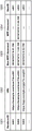
Fig. 12 is a diagram illustrating an example of the sequence management table 602 according to the present exemplary embodiment. The sequence management table 602 includes four columns 1201 to 1204.
The sequence ID column 1201 includes a value for defining identification information (hereinafter referred to as "sequence ID") for uniquely identifying the sequence information. The sequence information includes user information and information associated with the user indicating an operational state of the sequence. The sequence id column 1201 and the operational state of the sequence are associated with each other. The value included in the sequence id column 1201 also serves as an identifier that uniquely specifies a row of the sequence management table 602. Hereinafter, the value of the sequence id column 1201 is used to specify a row of the sequence management table 602. For example, a row having "s001" as the value of the sequence id column 1201 is described as "row s001".
The SequenceData column 1202 indicates the operating state at the point in time in the sequence indicated by the SequenceID column 1201. In the sequence data column 1202, information necessary to specify and/or restore the operating state of the sequence (hereinafter referred to as "sequence operating state data") is saved. Examples of the necessary information include an identifier of the operation screen and an operation status including a set value set with the operation screen.
The handover ID column 1204 includes an identifier (hereinafter referred to as "handover ID") for uniquely specifying a row of the handover management table 702 described below. The sequence management table 602 and the handover management table 702 are associated with each other through a handover id column 1204.
Fig. 7 is a block diagram illustrating a software configuration of the management server 103 according to the present exemplary embodiment. The CPU 411 reads a program stored in the ROM412 or HDD 414 of the management server 103 to the RAM 413, and executes the program to realize each of the software functional blocks. The handover management unit 701 manages information (hereinafter referred to as "handover information") for handing over the sequence information of the web application 601 from the mobile terminal 102 to the MFP 101. The handover management table 702 is a table for recording handover information. The handover management unit 701 and the handover management table 702 do not necessarily have to be arranged on the management server 103, but may be arranged on the application server 104. Further, the management server 103 may have other functions not illustrated in fig. 7.
Fig. 13 is a diagram illustrating an example of the handover management table 702 according to the present exemplary embodiment. The handover management table 702 includes five columns 1301 to 1305.
The handover id column 1301 includes a value defining an identifier for uniquely identifying the handover information, and corresponds to the handover id column 1204 of the sequence management table 602. The value included in the handover id column 1301 also serves as an identifier for uniquely specifying a row of the handover management table 702. In the exemplary embodiment described below, the value of the HandoverID column 1301 is used to specify its row. For example, a row having "h001" as a value of the HandoverID column 1301 is described as "row h001".
The URL column 1302 includes a Uniform Resource Locator (URL) to be accessed from the web browser 503 of the MFP101 (hereinafter, referred to as "handover URL") when the sequence information about the web application 601 is handed over to the MFP 101. The information included in the URL column 1302 is the URL of the web application 601, and the URL is different for each web application. In the present exemplary embodiment, as an example of the handover URL, a URL of a web application is used to which a value in the sequence id column 1201 is attached as a query string. The value in the sequence id column 1201 indicates the operation state of the sequence, and thus, the operation state of the sequence of the target web application can be specified and restored with the handover URL.
The Non-MFP-Accessed column 1303 includes information indicating the last date and time of access to the web application 601 of the application server 104 from a web browser other than the web browser 503 of the MFP101 in the corresponding sequence. The MFP-Accessed column 1304 includes information indicating the last date and time of access to the web application 601 from the web browser 503 of the MFP101 in the corresponding sequence. No value in a field in the MFP-Accessed column 1304 indicates that the web application 601 has not been Accessed from the web browser 503 of the MFP101 in the corresponding sequence.
The UserID column 1305 includes a user ID used to specify handover information associated with a logged-in user.
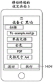
Before describing the sequence diagram in fig. 8, an overview of the operation setting handover process according to the present exemplary embodiment will be described with reference to fig. 14A to 14G. In the present exemplary embodiment, a description will be provided using an example in which the mobile terminal 102 and the MFP101 can operate a web application capable of transmitting scanned data to a destination specified by a user operation, and the user executes setting of the web application with a screen of the mobile terminal 102 or the MFP 101. Fig. 14A to 14D are diagrams illustrating transition of the setting screen in the mobile terminal 102. When the user inputs user information on the screen in fig. 14A and presses a "next" button 1401, the screen is transitioned to setting screen 1 in fig. 14B. When the user presses the "next" button 1402 after performing setting on the setting screen 1, the screen is transitioned to a setting screen 2 in fig. 14C. Similarly, when the "next" button 1403 is pressed, the screen is transitioned to the setting screen 3 in fig. 14D, and when the "execute" button 1404 is pressed, a scan execution instruction is transmitted to the MFP 101. Fig. 14E to 14G are diagrams illustrating transition of the setting screen in the MFP 101. The setting screen is similar to the setting screen shown in fig. 14B to 14D, and the setting screen transition is performed in a similar manner. For example, the user performs setting on the mobile terminal 102 with the setting screen 1 shown in fig. 14B, and presses the "next" button 1402 to make the screen transition to the setting screen 2 shown in fig. 14C. When the user logs in to the MFP101 while the setting screen 2 is being displayed, the user can continue to perform setting with the setting screen 2 of fig. 14F displayed on the MFP 101. Similarly, in the case where the setting screen 1 or the setting screen 3 is displayed on the mobile terminal 102, the user can continue to perform setting on the MFP101 from the setting screen displayed on the mobile terminal 102. When the user advances the handover setting screen 2 to the setting screen 3 of fig. 14G on the MFP101 and presses the "execute" button 1407, the MFP101 executes scanning and transmits a mail.
Fig. 8 is a sequence diagram illustrating a series of processes collectively executed by the MFP101, the mobile terminal 102, the management server 103, and the application server 104 of the present exemplary embodiment. In this sequence diagram, a description will be provided using an example in which the sequence is handed over to the MFP101 after the web application 601 provided by the application server 104 is operated with the mobile terminal 102.
The application server 104 provides the web application 601, and the web application 601 is called by the MFP101 and the mobile terminal 102. The management server 103 is used to manage information for handing over the operation state of the web application 601 from the mobile terminal 102 to the MFP 101.
First, in step S801, the mobile terminal 102 receives a user instruction and transmits a request including a user authentication request to the application server 104, that is, the user presses the "next" button 1401 in fig. 14A. At this point, the user accesses web application 601 using the URL as the start of the sequence. The URL that is the start of the sequence may be registered in a menu screen of the mobile terminal 102 or may be called from a dedicated application installed in the mobile terminal 102.
In step S802, the application server 104 performs user authentication by using user information including a user ID set by the user. In the present exemplary embodiment, as an example of the authentication method, the external authentication server performs authentication. In step S803, the application server 104 newly registers the sequence information in the sequence management table 602. At this time, the sequence information includes sequence operation state data and an authenticated user ID. In step S804, the application server 104 instructs the management server 103 to register the handover information based on the sequence information. At this time, the application server 104 transmits the URL of the web application 601 being executed by the mobile terminal 102 and the authenticated user ID as handover information. In step S805, the management server 103 newly registers the handover information in the handover management table 702. In step S806, the application server 104 executes the processing for the request in step S801. Herein, "request" refers to, for example, a process of requesting an operation screen in the sequence of the web application 601 (i.e., an operation in which the user presses a "next" button 1401 in fig. 14A to input an acquisition request for a next screen). The application server 104 specifies the state in the sequence from the sequence information registered in step S803, and executes processing appropriate to the request in step S801 (i.e., processing of generating a screen shown in fig. 14B in response to the screen acquisition request). In step S807, the application server 104 updates the sequence management table 602 with sequence information reflecting the processing performed in step S806. More specifically, application server 104 additionally updates the information in the SequenceData column 1202 of sequence management table 602 in response to the request. In step S808, the application server 104 returns a response to the request in step S801 to the mobile terminal 102 (displays the screen of fig. 14B).
In step S809, the mobile terminal 102 receives the user instruction and transmits a next request to the application server 104 (the user performs setting on the setting screen 1 in fig. 14B and presses the "next" button 1402). This request includes user information and information indicating the sequence.
In step S810, the application server 104 transmits access information (described below) to the management server 103. In step S811, when the management server 103 receives the access information, the management server 103 updates the handover information in the handover management table 702. More specifically, the management server 103 updates the value in the Non-MFP-Accessed column 1303 of the handover management table 702 with the system time.
In step S812, the application server 104 executes processing for the request in step S809 (recording settings such as "one-sided document" and "full color" set as in the setting screen 1 shown in fig. 14B, and generating the setting screen 2 shown in fig. 14C). The application server 104 specifies a state in the sequence from information indicating the sequence included in the request, and performs processing appropriate for the request. In step S813, the application server 104 updates the sequence management table 602 with sequence information (i.e., setting information such as "double-sided document" and "full color" set with the setting screen 1 in fig. 14B) reflecting the processing performed in step S812. In step S814, the application server 104 returns a response to the request in step S809 to the mobile terminal 102 (i.e., displays the screen of fig. 14C).
The processing in steps S809 to S814 is executed each time the mobile terminal 102 receives a user operation performed on the web browser and transmits a request by accessing the application server 104 (a description will be provided hereinafter on the assumption that the setting screen 2 of fig. 14C is being displayed on the mobile terminal 102).
Subsequently, a description will be provided of processing based on an assumption that the information processing apparatus operated by the user is changed from the mobile terminal 102 to the MFP 101.
In step S815, when the user has logged in to the MFP101, the MFP101 receives the user information and performs user authentication. In the present exemplary embodiment, the MFP101 performs authentication by using the same external authentication server as that used by the application server 104 in step S802. In step S816, the MFP101 acquires, from the handover management table 702 in the management server 103, handover information associated with user information about the user (hereinafter referred to as "logged-in user") that has logged in step S815. In step S817, the MFP101 determines whether or not there is handover information for the logged-in user. If there is handover information (yes in step S817), the processing proceeds to step S818. If there is no handover information (no at step S817), the processing proceeds to step S828.
In step S828, the MFP101 displays a menu screen on which application buttons are arranged.
In step S818, the MFP101 starts the web browser 503 and accesses the handover URL included in the handover information (i.e., the acquisition request to the setting screen 2 in fig. 14F).
In step S819, the application server 104 transmits the access information to the management server 103. In step S820, the management server 103 updates the handover information in the handover management table 702. More specifically, the management server 103 updates the value in the MFP-Accessed column 1304 with the system time.
In step S821, the application server 104 executes processing for the request in step S818. The application server 104 refers to the sequence management table 602 based on the sequence information included in the handover information, specifies the states in the sequence (such as the operation screen and the operation history), and executes processing appropriate to the request (in response to an acquisition request for the setting screen 2 shown in fig. 14F, the application server 104 generates the setting screen 2 in fig. 14F in which the operation history is retained and reflected). In step S822, the application server 104 updates the sequence management table 602 with the sequence information reflecting the processing executed in step S821.
In step S823, the application server 104 determines whether the sequence is completed. If the sequence is completed (yes to the step S823), the processing proceeds to a step S824. If the sequence has not been completed (NO in step S823), the processing proceeds to step S827.
In step S827, the application server 104 returns a response to the request in step S818 to the MFP101 (i.e., displays the screen of fig. 14F). The processing in steps S818 to S827 is executed each time the MFP101 receives a user operation performed on the web browser 503 and transmits a request to the application server 104. It is assumed that the request processing in step S818 at the second time and thereafter is executed based on a user instruction provided via the MFP 101. (for example, the user presses the "next" button 1406 on the setting screen 2 in fig. 14F to request acquisition of the setting screen 3 in fig. 14G. Then the user presses the "execute" button 1407 on the setting screen 3 in fig. 14G to request execution of the scanning process using the MFP 101.) in step S823, if the sequence is completed (that is, if the user has pressed the "execute" button 1407 on the setting screen 3 in fig. 14G in step S818), the process proceeds to step S824. In step S824, the application server 104 instructs the management server 103 to delete the handover information. In step S825, the management server 103 deletes the corresponding handover information from the handover management table 702.
In step S826, the application server 104 deletes the sequence information from the sequence management table 602.
Here, if there is handover information relating to the user who has logged in to the MFP101, the web browser has been automatically started in step S818. However, the present exemplary embodiment is not limited thereto. A button for calling the handover information may be displayed on the menu screen as one of application buttons so that the web browser is started when the user presses the button.
The effect of the sequence diagram will be described. The user can hand over the operation state of the web application 601 operated halfway using the mobile terminal 102 by logging in to the MFP 101.
Fig. 9A and 9B are flowcharts illustrating processing performed by the application server 104 according to the present exemplary embodiment. A description will be provided of processing from receiving a request from the web browser of the MFP101 or the mobile terminal 102 to returning a response. The flowcharts in fig. 9A and 9B correspond to the processing executed by the application server 104 in the series of processing shown in the sequence diagram in fig. 8. The CPU 411 reads a program stored in the HDD 414 of the application server 104 to the RAM 413, and executes the program to perform the corresponding operation in the steps of the flowcharts in fig. 9A and 9B.
In step S901, the web application 601 receives a hypertext transfer protocol (HTTP) request from the web browser of the MFP101 or the mobile terminal 102. Hereinafter, in the description of this flowchart, the HTTP request received in step S901 will be simply referred to as a "request". In step S902, the web application 601 determines whether the request is a user authentication request. If the request is a user authentication request (yes at step S902), the processing proceeds to step S950. If the request is not a user authentication request (no at step S902), the processing proceeds to step S903.
In step S903, the web application 601 determines whether the request source has been authenticated by the user. More specifically, web application 601 makes the determination based on whether the request includes information that can identify the user. For example, the request may include authentication information in a cookie or information capable of identifying the user in an HTTP header. If the request source has been authenticated by the user (yes at step S903), the processing proceeds to step S904. If the request source has not been authenticated (no in step S903), the processing proceeds to step S920. Hereinafter, in the description of this flowchart, the user determined as the authenticated user in step S903 will be referred to as a "logged-in user".
In step S904, the web application 601 identifies the type of the request source device (i.e., the MFP101 or the mobile terminal 102).
In step S905, the web application 601 determines whether the request includes information for specifying the sequence of the web application 601. In the present exemplary embodiment, a description will be provided using an example in which such a determination is made based on whether or not a sequence ID is attached to a request URL as a query string. However, another method may be adopted. For example, information that can specify a sequence may be included in a cookie or an HTTP header. If the request includes information specifying the sequence (yes at step S905), the processing proceeds to step S906. If the request does not include the information (NO at step S905), the processing proceeds to step S930.
In step S906, the web application 601 extracts, from the sequence management table 602, sequence information including a sequence ID conforming to the sequence ID included in the query attached to the request URL. More specifically, the web application 601 extracts a record from the sequence ID column 1201 that has a value that conforms to the value of the sequence ID included in the query appended to the requesting URL. In step S907, the web application 601 determines whether the sequence information is extracted in step S906. If the sequence information is extracted (yes at step S907), the processing proceeds to step S908. If the sequence information is not extracted (no at step S907), the processing proceeds to step S930.
In step S908, the web application 601 transmits the access information to the handover management unit 701 of the management server 103. The access information includes the type of the request source device identified in step S903 and the handover ID (i.e., the value in the handover ID column 1204) included in the sequence information extracted in step S906. In step S909, the web application 601 receives a response to the operation in step S908 from the handover management unit 701 of the management server 103. In step S910, the web application 601 determines whether an error is indicated in the response received in step S909. If an error is indicated in the response (yes in step S910), the processing proceeds to step S940. If no error is indicated in the response (no in step S910), the processing proceeds to step S911.
In step S911, the web application 601 specifies the operation state in the sequence from the sequence operation state data (i.e., information in the sequence data column 1202) included in the sequence information extracted in step S906, and performs processing appropriate to the request. In step S912, the web application 601 updates the sequence operation state data in the sequence management table 602 with the state of the sequence reflecting the processing performed in step S911.
In step S913, the web application 601 determines whether the target sequence has been completed to the end based on the sequence operation state data. If the sequence has been completed (yes to the step S913), the processing proceeds to a step S914. If the sequence has not been completed (NO at step S913), the processing proceeds to step S917.
In step S914, the web application 601 transmits a handover information deletion instruction for deleting the handover information to the handover management unit 701 of the management server 103. Here, the web application 601 includes the handover ID (the value in the handover ID column 1204) in the sequence information extracted in step S906 as information for specifying the deletion target in the deletion instruction to be transmitted. In step S915, the web application 601 receives a response to the deletion instruction in step S914 from the handover management unit 701 of the management server 103. In step S916, the web application 601 deletes the sequence information from the sequence management table 602. The sequence information to be deleted is sequence information having a sequence ID in the sequence ID column 1201 that matches the sequence ID included in the query attached to the request URL.
In step S917, in response to the request in step S901, the web application 601 returns the result of the processing in step S911 to the request source device, and ends the processing.
In step S920, in response to the request in step S901, the web application 601 returns information for the user authentication screen to the request source device, and ends the processing.
In step S930, the web application 601 newly issues a sequence ID. In step S931, the web application 601 newly registers the sequence information having the sequence ID issued in step S930 in the sequence management table 602. The issued serial ID, current serial operation state data, and user ID of the logged-in user are registered in the sequence ID column 1201, the sequence data column 1202, and the UserID column 1203, respectively. At this time, the HandoverID column 1204 is blank.
In step S932, the web application 601 transmits a handover information registration instruction for registering handover information to the handover management unit 701 of the management server 103. Here, the web application 601 includes, as handover information, a handover URL (URL of the web application 601 to which the sequence ID is attached as a query), a user ID of the logged-in user, and the type of the request source apparatus identified in step S903, in the registration instruction to be transmitted. In step S933, the web application 601 receives a response to the registration instruction in step S932 from the handover management unit 701 of the management server 103. The response includes a handover ID for specifying the registered handover information. In step S934, the web application 601 registers the handover ID received in step S933 in the HandoverID column 1204 of the sequence management table 602. Next, the web application 601 advances the process to step S911 and executes the subsequent process.
In step S940, in response to the request in step S901, the web application 601 returns error information for prohibiting a subsequent operation to the request source apparatus, and ends the processing.
In step S950, the web application 601 performs user authentication. In the present exemplary embodiment, an authentication method using an external authentication server is used as an example of the authentication method, as described with reference to fig. 8. In step S951, in response to the request in step S901, the web application 601 returns the result of user authentication to the request source device, and ends the processing.
The effects of the flowcharts in fig. 9A and 9B will be described. The application server 104 is capable of registering user information and a sequence operation state of the web application 601 in association with each other, and is capable of acquiring and updating the registered information each time the user accesses the web application 601 via the web browser of the MFP101 or the mobile terminal 102. The application server 104 can notify the management server 103 of the registered information.
Fig. 10A to 10D are flowcharts each illustrating a process of the management server 103 according to the present disclosure. The CPU 411 reads a program stored in the HDD 414 of the management server 103 to the RAM 413, and executes the program to perform operations in the respective steps of the flowcharts of fig. 10A to 10D.
Fig. 10A is a flowchart illustrating processing executed when the management server 103 receives a handover information registration instruction from the application server 104. The flowchart in fig. 10A corresponds to the processing executed by the management server 103 in steps S804 to S805 of the sequence diagram in fig. 8.
In step S1001, the handover management unit 701 receives a handover information registration instruction from the application server 104. The registration instruction includes a handover URL, a user ID, and the type of the request source apparatus identified in step S903.
In step S1002, the handover management unit 701 newly issues a handover ID. In step S1003, the handover management unit 701 newly registers the handover information having the handover ID issued in step S1002 in the handover management table 702. The handover ID, handover URL, and user ID are registered in a handover ID column 1301, a URL column 1302, and a UserID column 1305, respectively. If the request source device is the MFP101, the system time is registered in the MFP-Accessed column 1304, and if the request source device is not the MFP101, the system time is recorded in the Non-MFP-Accessed column 1303.
In step S1004, in response to the registration instruction in step S1001, the handover management unit 701 transmits a response indicating completion of registration to the application server 104, and ends the processing. Here, the response includes the handover ID issued in step S1002.
Fig. 10B is a flowchart illustrating processing performed when the management server 103 receives access information from the application server 104. The flowchart in fig. 10B corresponds to the processing executed by the management server 103 in steps S810 to S811 and steps S819 to S820 of the sequence diagram of fig. 8.
In step S1010, the handover management unit 701 receives access information from the application server 104. The access information includes the handover ID and the type of the request source device identified in step S903. In step S1011, the handover management unit 701 extracts handover information having a handover ID conforming to the received handover ID in the handover ID column 1301 from the handover management table 702.
In step S1012, the handover management unit 701 determines whether or not handover information is extracted in step S1011. If the handover information is extracted (yes at step S1012), the processing proceeds to step S1013. If the handover information cannot be extracted (no in step S1012), the processing proceeds to step S1030. In step S1030, the handover management unit 701 transmits an error indicating that the handover information does not exist to the application server 104, and ends the processing.
In step S1013, the handover management unit 701 identifies whether the type of the device that is the transmission source of the access information received from the application server 104 in step S1010 is an MFP. If the type of the apparatus is the MFP (yes in step S1013), the processing proceeds to step S1014. If the type of the apparatus is not the MFP (no in step S1013), the processing proceeds to step S1015.
In step S1014, the handover management unit 701 registers the system time in the field of the MFP-Accessed column 1304 corresponding to the handover information extracted from the handover management table 702 in step S1011. Then, the process proceeds to step S1017.
In step S1015, the handover management unit 701 determines whether or not the field of the MFP-Accessed column 1304 corresponding to the handover information extracted in step S1011 is blank (unset value). If the corresponding field of the MFP-Accessed column 1304 is blank (YES in step S1015), the processing proceeds to step S1016. If the corresponding field of the MFP-Accessed column 1304 is not blank (NO in step S1015), the processing proceeds to step S1020. In step S1020, the handover management unit 701 returns an error indicating that the subsequent operation is prohibited to the application server 104, and ends the processing.
In step S1016, the handover management unit 701 sets the system time to the field of the Non-MFP-Accessed column 1303 corresponding to the handover information extracted in step S1011, and updates the handover management table 702.
In step S1017, the handover management unit 701 transmits a response to the application server 104 indicating that the access information was normally received in step S1010, and ends the processing.
Fig. 10C is a flowchart illustrating processing executed when the management server 103 receives a handover information deletion instruction from the application server 104. The processing in the flowchart in fig. 10C corresponds to the processing executed by the management server 103 in steps S824 to S825 of the sequence diagram in fig. 8.
In step S1040, the handover management unit 701 receives a handover information deletion instruction from the application server 104. The deletion instruction includes a handover ID. In step S1041, the handover management unit 701 determines whether the handover management table 702 includes handover information indicating that the handover management unit 701 deletes. More specifically, the handover management unit 701 determines whether there is a record having a value conforming to the value of the handover ID received in step S1040 in the handover ID column 1301. If the handover information exists (yes in step S1041), the processing proceeds to step S1042. If the handover information does not exist (no in step S1041), the processing proceeds to step S1050. In step S1050, the handover management unit 701 transmits a response indicating that the handover information to be deleted does not exist to the application server 104, and ends the processing.
In step S1042, the handover management unit 701 deletes the record having a value in the handover ID column 1301 that matches the value of the handover ID received in step S1040 from the handover management table 702.
In step S1043, in response to the deletion instruction in step S1040, the handover management unit 701 notifies the application server 104 that the handover information has been deleted, and ends the processing.
Fig. 10D is a flowchart illustrating processing executed when the management server 103 receives a handover information acquisition request from the MFP 101. The flowchart in fig. 10D corresponds to the processing executed by the management server 103 in step S816 of the sequence diagram in fig. 8.
In step S1060, the handover management unit 701 receives a handover information acquisition request from the MFP 101. The user ID is included in the acquisition request.
In step S1061, the handover management unit 701 refers to the handover management table 702, and extracts handover information corresponding to the user ID included in the acquisition request.
In step S1062, the handover management unit 701 determines that handover information has been extracted in step S1061. If the handover information has been extracted (yes at step S1062), the processing proceeds to step S1063. If the handover information cannot be extracted (no to step S1062), the processing proceeds to step S1064.
In step S1063, the handover management unit 701 transmits the extracted handover information to the MFP101 as a response to the acquisition request in step S1060, and ends the processing.
In step S1064, in response to the operation in step S1060, the handover management unit 701 transmits a notification that there is no handover information to the MFP101, and ends the processing.
Effects of the flowcharts in fig. 10A to 10D will be described. The sequence information registered in the management server 103 may be updated by an instruction from the web application. The management server 103 can provide the sequence information according to the acquisition request from the MFP 101.
Fig. 11 is a flowchart illustrating processing from login processing to processing of displaying a menu screen executed by the MFP101 according to the present disclosure. The flowchart in fig. 11 corresponds to the processing executed by the MFP101 in steps S815 to S828 of the sequence diagram in fig. 8. The CPU 211 reads a program stored in the ROM 212 or HDD 214 of the MFP101 to the RAM 213, and executes the program to perform operations in respective steps in the flowchart of fig. 11.
In step S1101, the login management unit 501, which has received login information from the user along with the login operation, performs user authentication by using an external authentication server. The external authentication server used herein is the same as the authentication server used by the web application 601 to perform authentication.
In step S1102, if the user authentication is successful (yes in step S1102), the processing proceeds to step S1103. If the user authentication fails (no in step S1102), the processing proceeds to step S1120. In step S1120, the login management unit 501 displays an error and ends the processing.
In step S1103, the menu display unit 502 transmits a handover information acquisition request to the handover management unit 701 of the management server 103. Here, in order to acquire only the handover information corresponding to the logged-in user, the menu display unit 502 includes the user ID authenticated in step S1101 in the acquisition request to be transmitted.
In step S1104, the menu display unit 502 receives a response to the acquisition request from the handover management unit 701 of the management server 103.
In step S1105, the menu display unit 502 determines whether the handover information is included in the response received in step S1104. If the handover information exists (yes at step S1105), the processing proceeds to step S1106. If the handover information does not exist (no at step S1105), the processing proceeds to step S1110.
In step S1106, in order to access the handover URL included in the handover information, the menu display unit 502 calls the web browser 503. In step S1107, the web browser 503 accesses the handover URL. Here, the web browser 503 includes authentication information about the user authenticated in step S1101 in the request to be transmitted. Thereafter, the web browser 503 receives a user operation, communicates with the web application 601, and executes the web application 601 as necessary.
In step S1110, the menu display unit 502 displays the menu screen on which the application buttons are arranged, and ends the processing.
The effect of the flowchart in fig. 11 will be described. By simply logging in to the MFP101, the user can acquire the handover information associated with the user registered in the management server 103 and hand over the operation state of the web application 601 indicated in the handover information to the MFP 101.
As described above, with the method described in the present exemplary embodiment, the user can hand over the operation state of the web application 601 operated by the mobile terminal 102 by simply logging in to the MFP 101. Therefore, user convenience can be enhanced.
A second exemplary embodiment of the present invention will be described below. In the first exemplary embodiment, if there is handover information for a user who has logged in when the user has logged in to the MFP101, the handover process is always performed. However, in some cases, even if there is handover information, the handover process should not be performed. For example, in some cases, if the user has already logged into another MFP and has handed over the handover information before the user has logged into the MFP101, the handover information should not be handed over when the user logs into the MFP101 without the operation having been completed to the end of the sequence. In a case where the user logs in to the MFP101 after a long time has elapsed since the operation was performed on the web application of the information processing apparatus and the handover information was registered, there is a possibility that the handover process should not be performed.
In the present exemplary embodiment, if there is handover information when the user logs in to the MFP101, the MFP101 determines whether a predetermined condition is satisfied, and does not perform handover processing depending on the result of the determination. The present exemplary embodiment is a variation of the first exemplary embodiment, and therefore, only the differences will be described.
Processing of the MFP101 according to the present exemplary embodiment will be described. The flowchart in fig. 15 is a variation of the flowchart in fig. 11. This flowchart differs from the flowchart in fig. 11 in that steps S1501 to S1503 are newly added between steps S1105 and S1106. Further, steps S1501 and S1502 are each an independent conditional branch, and therefore, it is not always necessary to add both steps S1501 and S1502 to the process, and either of steps S1501 and S1502 may be added.
In step S1501, the menu display unit 502 determines whether the handover information received in step S1104 has been handed over. More specifically, if time is recorded in the MFP-Accessed column 1304 of the handover management table 702, the menu display unit 502 determines that the handover information has been handed over. If the handover information has been handed over (yes in step S1501), the processing proceeds to step S1503. If the handover information has not been handed over (no in step S1501), the processing proceeds to step S1502.
In step S1502, the menu display unit 502 determines whether a certain period of time (e.g., 6 hours) has elapsed since the web application 601 was operated with the mobile terminal 102 and the handover information was updated. More specifically, the menu display unit 502 compares the time recorded in the field of the Non-MFP-Accessed column 1303 corresponding to the handover information received in step S1140 with the current system time, and determines whether a certain period of time has elapsed. If a certain period of time has elapsed (yes in step S1502), the processing proceeds to step S1503. If a certain period of time has not elapsed (no in step S1502), the processing proceeds to step S1106.
In step S1503, the menu display unit 502 displays a menu screen including a button for calling the handover information received in step S1104 as one of the application buttons. More specifically, the shortcut of the handover URL is displayed as an application button for calling handover information. This configuration prevents handover information from always being handed over in the presence of handover information, i.e., if a predetermined condition is satisfied, handover information is not handed over in the presence thereof. By displaying a shortcut of the handover URL as an application button, the handover information can be handed over only when the user desires so.
With the method described in the present exemplary embodiment, if a predetermined condition is satisfied, even if there is handover information for a logged-in user, the handover process is not performed, and the handover information is handed over only when the user desires.
OTHER EMBODIMENTS
The embodiment(s) of the present invention can also be implemented by reading out and executing computer-executable instructions (e.g., one or more programs) recorded on a storage medium (also can be more fully referred to as "non-transitory computer-readable storage medium") to perform the functions of one or more of the above-described embodiments and/or a computer of a system or apparatus including one or more circuits (e.g., application Specific Integrated Circuits (ASICs)) for performing the functions of one or more of the above-described embodiments, and by a computer of the system or apparatus by, for example, reading out and executing the computer-executable instructions from the storage medium to perform the functions of one or more of the above-described embodiments and/or controlling the one or more circuits to perform the functions of the above-described embodiment(s)To the functions of one or more embodiments of the invention. The computer may include one or more processors (e.g., central Processing Unit (CPU), micro Processing Unit (MPU)) and may include a separate computer or a network of separate processors to read out and execute computer-executable instructions. The computer-executable instructions may be provided to the computer, for example, from a network or a storage medium. The storage medium may include, for example, a hard disk, a Random Access Memory (RAM), a read-only memory (ROM), a storage device for a distributed computing system, an optical disk such as a Compact Disk (CD), a Digital Versatile Disk (DVD), or a Blu-ray disk (BD) TM ) One or more of a flash memory device, a memory card, etc.
The embodiments of the present invention can also be realized by a method in which software (programs) that perform the functions of the above-described embodiments are supplied to a system or an apparatus through a network or various storage media, and a computer or a Central Processing Unit (CPU), a Micro Processing Unit (MPU) of the system or the apparatus reads out and executes the methods of the programs.
While the present invention has been described with reference to exemplary embodiments, it is to be understood that the invention is not limited to the disclosed exemplary embodiments. It will be understood that the present invention has been described above by way of example only and modifications of detail can be made within the scope of the invention.
Claims (13)
1. A system includes an information processing apparatus (102), an image forming apparatus (101), and a Web server (104),
wherein the Web server (104) performs:
in an operation screen involving screen transition, an operation screen including a setting screen for executing a process on an image forming apparatus is provided to an information processing apparatus (102) and the image forming apparatus (101), and the information processing apparatus and the image forming apparatus make a series of settings for the process while sequentially transitioning the provided operation screen,
wherein the information processing apparatus (102) executes:
displaying an operation screen provided in the providing;
receiving an operation on the displayed operation screen from a user, wherein the operation includes an operation for setting contents and screen transition; and
transmitting the operation information on the operation and the identification information on the user received in the receiving to a Web server (104);
wherein the Web server (104) further performs:
registering (S803) first information in association with identification information about a user, wherein the first information includes setting content and information representing a first operation screen, the first operation screen being an operation screen provided in the providing and a transition to the first operation screen being caused by a received operation, the setting content being set as a result of the received operation performed on a previous operation screen prior to the transition to the first operation screen,
wherein the image forming apparatus (101) performs:
identifying a user operating the image forming apparatus;
transmitting identification information about the user identified in the identifying to the Web server (104); and
displaying an operation screen provided in the providing,
wherein in the providing, setting contents and a first operation screen are provided to the image forming apparatus based on first information associated with the identification information on the user transmitted in the transmitting, which is registered in the registration, and the first operation screen is displayed in a state in which the setting contents set on a previous operation screen before the transition to the first operation screen are retained in the displaying.
2. The system of claim 1, wherein the first and second sensors are disposed in a common housing,
wherein the image forming apparatus further performs: acquiring second information corresponding to the first information associated with the identification information on the specified user,
wherein the image forming apparatus (101) is configured to access the Web server using the second information acquired in the acquisition and the provided operation screen displayed in the display.
3. The system of claim 2, wherein the first and second sensors are arranged in a single package,
wherein the Web server further executes issuing of an instruction for instructing registration of the second information in association with identification information about a user of the information processing apparatus.
4. The system of claim 3, further comprising a management server configured to manage the second information;
wherein, in the issuing instruction, the management server is instructed to register the second information.
5. The system according to claim 4, wherein in the acquisition, the second information associated with the identification information on the specified user is acquired from the management server by the identification information on the specified user transmitted to the management server.
6. The system according to claim 2, wherein the operation setting contents are information including setting information set in each operation screen.
7. The system as set forth in claim 2, wherein,
wherein, in the second information, information corresponding to an identifier of the operation screen and the operation setting contents is attached to a uniform resource locator URL for accessing the Web server; and
in the display, an operation screen obtained by accessing the Web server using the URL to which the information is attached is displayed.
8. The system as set forth in claim 2, wherein,
wherein a date and time when the user accessed the Web server is included in the second information, an
Wherein the Web server is configured to update the date and time of the access included in the second information every time the access is performed.
9. The system of claim 3, wherein the Web server further executes
In a case where transition of the operation screen is made to the end of the predetermined series of processes by an operation of the user, information associated with the identification information on the user registered is deleted, an
An instruction to delete the second information associated with the deleted information is issued.
10. The system of claim 2, wherein the operation screen is an operation screen of a web application.
11. The system according to claim 1, wherein the operation screen is an operation screen for executing a scanning process or a printing process on the image forming apparatus.
12. A control method of a system including an information processing apparatus (102), an image forming apparatus (101), and a Web server (104),
wherein, by the Web server, in an operation screen involving screen transition, an operation screen including a setting screen for executing processing on the image forming apparatus is provided to the information processing apparatus and the image forming apparatus, and the information processing apparatus and the image forming apparatus make a series of settings for the processing while sequentially transitioning the provided operation screen,
the control method comprises the following steps:
executing, by an information processing apparatus (102):
displaying an operation screen provided in the providing;
receiving an operation on the displayed operation screen from a user, wherein the operation includes an operation for setting contents and screen transition; and
transmitting operation information on the received operation and identification information on the user to the Web server,
wherein, by the Web server, first information is registered in association with identification information on a user, wherein the first information includes setting content and information representing a first operation screen, the first operation screen being an operation screen provided in the providing and a transition to the first operation screen being caused by a received operation, the setting content being set as a result of the received operation performed on a previous operation screen before the transition to the first operation screen,
wherein the image forming apparatus (101) performs:
identifying a user operating the image forming apparatus;
transmitting identification information about the user identified in the identifying to the Web server (104); and
displaying an operation screen provided in the providing,
wherein in the providing, setting contents and a first operation screen are provided to the image forming apparatus based on first information associated with the identification information on the user transmitted in the transmitting, which is registered in the registration, and the first operation screen is displayed in a state in which the setting contents set on a previous operation screen before the transition to the first operation screen are retained in the displaying.
13. A non-transitory computer-readable storage medium storing a program that causes a computer to execute a control method for controlling a system including an information processing apparatus (102), an image forming apparatus (101), and a Web server (104),
wherein the information processing apparatus and the image forming apparatus are provided with an operation screen including a setting screen for executing a process on the image forming apparatus in an operation screen involving screen transition by the Web server, and the information processing apparatus and the image forming apparatus make a series of settings for the process while sequentially transitioning the provided operation screen,
the control method comprises the following steps:
executing, by an information processing apparatus (102):
displaying an operation screen provided in the providing;
receiving an operation on the displayed operation screen from a user, wherein the operation includes an operation for setting contents and screen transition; and
transmitting operation information on the received operation and identification information on the user to the Web server,
wherein, by the Web server, first information is registered in association with identification information on a user, wherein the first information includes setting content and information indicating a first operation screen, the first operation screen being an operation screen provided in the providing and a transition to the first operation screen being caused by a received operation, the setting content being set as a result of the received operation performed on a previous operation screen before the transition to the first operation screen,
wherein the image forming apparatus (101) performs:
identifying a user operating the image forming apparatus;
transmitting identification information about the user identified in the identification to the Web server (104); and
displaying an operation screen provided in the providing,
wherein in the providing, setting contents and a first operation screen are provided to the image forming apparatus based on first information associated with the identification information on the user transmitted in the transmitting, which is registered in the registration, and the first operation screen is displayed in a state in which the setting contents set on a previous operation screen before the transition to the first operation screen are retained in the displaying.
Applications Claiming Priority (2)
| Application Number | Priority Date | Filing Date | Title |
|---|---|---|---|
| JP2019-074415 | 2019-04-09 | ||
| JP2019074415A JP7330735B2 (en) | 2019-04-09 | 2019-04-09 | Information processing system and its control method |
Publications (2)
| Publication Number | Publication Date |
|---|---|
| CN111800554A CN111800554A (en) | 2020-10-20 |
| CN111800554B true CN111800554B (en) | 2022-11-15 |
Family
ID=70049842
Family Applications (1)
| Application Number | Title | Priority Date | Filing Date |
|---|---|---|---|
| CN202010257433.0A Active CN111800554B (en) | 2019-04-09 | 2020-04-03 | Information processing system, method and storage medium |
Country Status (4)
| Country | Link |
|---|---|
| US (2) | US11218608B2 (en) |
| EP (1) | EP3723355B1 (en) |
| JP (1) | JP7330735B2 (en) |
| CN (1) | CN111800554B (en) |
Families Citing this family (1)
| Publication number | Priority date | Publication date | Assignee | Title |
|---|---|---|---|---|
| JP7451101B2 (en) * | 2019-07-05 | 2024-03-18 | キヤノン株式会社 | Information processing system and its control method |
Citations (3)
| Publication number | Priority date | Publication date | Assignee | Title |
|---|---|---|---|---|
| CN102006381A (en) * | 2009-08-31 | 2011-04-06 | 京瓷美达株式会社 | Image forming system and image forming apparatus |
| JP2016201744A (en) * | 2015-04-13 | 2016-12-01 | キヤノン株式会社 | Information processing apparatus and control method therefor, data transmitter and control method therefor, and program |
| CN108995403A (en) * | 2017-06-06 | 2018-12-14 | 柯尼卡美能达株式会社 | Print system and the computer-readable recording medium for storing program |
Family Cites Families (20)
| Publication number | Priority date | Publication date | Assignee | Title |
|---|---|---|---|---|
| JP2001243165A (en) * | 2000-03-02 | 2001-09-07 | Fujitsu Ltd | Shared-information use system, method and recording medium |
| US8319989B2 (en) * | 2006-02-21 | 2012-11-27 | Ricoh Company, Ltd. | Image processing apparatus for processing and communicating with an information processing apparatus which does not have an image processing apparatus driver software |
| JP5451372B2 (en) * | 2009-12-28 | 2014-03-26 | キヤノン株式会社 | Information processing system, information processing method, and program |
| JP2011191888A (en) * | 2010-03-12 | 2011-09-29 | Canon Inc | Image forming apparatus, control method and program |
| JP5616695B2 (en) * | 2010-06-18 | 2014-10-29 | キヤノン株式会社 | Image processing apparatus, control method thereof, and program |
| JP2012185651A (en) * | 2011-03-04 | 2012-09-27 | Canon Inc | Information processor, information processing system, information processor control method and program |
| JP5751910B2 (en) * | 2011-04-26 | 2015-07-22 | キヤノン株式会社 | Server, server control method and program |
| JP6060651B2 (en) * | 2012-01-18 | 2017-01-18 | 株式会社リコー | Electronic device, information processing system, information processing apparatus, information processing method, and program |
| JP2014026163A (en) | 2012-07-27 | 2014-02-06 | Konica Minolta Inc | Image forming apparatus, control program of image forming apparatus, and image forming system |
| JP5920581B2 (en) | 2012-08-29 | 2016-05-18 | コニカミノルタ株式会社 | Print server printing system |
| JP2014175882A (en) | 2013-03-11 | 2014-09-22 | Canon Marketing Japan Inc | Image processing system, processing method therefor and program |
| JP2015125620A (en) * | 2013-12-26 | 2015-07-06 | キヤノン株式会社 | Information processor, control method therefor, program, and information processing system |
| WO2015136940A1 (en) * | 2014-03-14 | 2015-09-17 | Canon Kabushiki Kaisha | Information processing apparatus, method for controlling information processing apparatus, and storage medium |
| JP6429583B2 (en) * | 2014-10-10 | 2018-11-28 | キヤノン株式会社 | Image processing apparatus, control method therefor, and computer program |
| JP2017108338A (en) | 2015-12-11 | 2017-06-15 | キヤノン株式会社 | Information processing device, information processing device control method, mobile terminal, mobile terminal control method, and program |
| JP6613940B2 (en) | 2016-02-10 | 2019-12-04 | 株式会社リコー | Information processing system, setting method, information device, and program |
| US10310782B2 (en) * | 2016-04-20 | 2019-06-04 | Ricoh Company, Ltd. | Image forming apparatus having a scanner, information processing system having the same, and information processing method using the same |
| JP6761304B2 (en) * | 2016-08-26 | 2020-09-23 | キヤノン株式会社 | Information processing system, information processing device and its control method, and program |
| JP6929147B2 (en) * | 2017-06-29 | 2021-09-01 | キヤノン株式会社 | Image processing device, its control method, and program |
| JP6417468B2 (en) | 2017-12-25 | 2018-11-07 | キヤノン株式会社 | Information processing apparatus, control method thereof, and program |
-
2019
- 2019-04-09 JP JP2019074415A patent/JP7330735B2/en active Active
-
2020
- 2020-03-26 EP EP20165843.2A patent/EP3723355B1/en active Active
- 2020-04-03 US US16/840,121 patent/US11218608B2/en active Active
- 2020-04-03 CN CN202010257433.0A patent/CN111800554B/en active Active
-
2021
- 2021-11-09 US US17/522,747 patent/US11695886B2/en active Active
Patent Citations (3)
| Publication number | Priority date | Publication date | Assignee | Title |
|---|---|---|---|---|
| CN102006381A (en) * | 2009-08-31 | 2011-04-06 | 京瓷美达株式会社 | Image forming system and image forming apparatus |
| JP2016201744A (en) * | 2015-04-13 | 2016-12-01 | キヤノン株式会社 | Information processing apparatus and control method therefor, data transmitter and control method therefor, and program |
| CN108995403A (en) * | 2017-06-06 | 2018-12-14 | 柯尼卡美能达株式会社 | Print system and the computer-readable recording medium for storing program |
Also Published As
| Publication number | Publication date |
|---|---|
| EP3723355B1 (en) | 2023-12-06 |
| JP7330735B2 (en) | 2023-08-22 |
| JP2020174262A (en) | 2020-10-22 |
| US11218608B2 (en) | 2022-01-04 |
| CN111800554A (en) | 2020-10-20 |
| US20200329162A1 (en) | 2020-10-15 |
| KR20200119196A (en) | 2020-10-19 |
| EP3723355A1 (en) | 2020-10-14 |
| US11695886B2 (en) | 2023-07-04 |
| US20220070313A1 (en) | 2022-03-03 |
Similar Documents
| Publication | Publication Date | Title |
|---|---|---|
| CN104917917B (en) | Image forming apparatus, system, and information processing method | |
| JP6562660B2 (en) | COMMUNICATION DEVICE, ITS CONTROL METHOD, AND PROGRAM | |
| EP3070593B1 (en) | Information processing apparatus and method of controlling the same, and storage medium | |
| JP6656026B2 (en) | Information processing apparatus, information processing control method, and computer program | |
| JP2024050669A (en) | JOB PROCESSING APPARATUS, CONTROL METHOD FOR JOB PROCESSING APPARATUS, AND PROGRAM - Patent application | |
| JP6560559B2 (en) | Information processing apparatus, information processing apparatus control method, and program | |
| CN112019695B (en) | Information processing system, control method, and storage medium | |
| KR102277214B1 (en) | Communication terminal, control method of communication terminal, and storage medium | |
| JP2011124957A (en) | Information processor, method to control the same, program, and memory medium | |
| CN111800554B (en) | Information processing system, method and storage medium | |
| JP2018005295A (en) | Program and mobile terminal | |
| US9706067B2 (en) | Information processing terminal and non-transitory readable recording medium for file transfer and file processing | |
| CN107995385B (en) | Information processing apparatus, control method therefor, and storage medium | |
| KR102659464B1 (en) | Information processing system, method and storage medium | |
| JP2023072169A (en) | Print system and method | |
| JP7141211B2 (en) | Information processing device, information processing method, and program | |
| JP2024059952A (en) | Information processing device | |
| JP2017199219A (en) | Driver program | |
| JP2023082794A (en) | Information processing system, information processing device, control method therefor, and program | |
| JP2021100795A (en) | Image formation device and control method and program of the same | |
| CN112188023A (en) | Information processing system, control method thereof, and storage medium | |
| JP2021019339A (en) | Mobile terminal, information processing system, mobile terminal control method, and program | |
| JP2018136609A (en) | Information processing system, information processing device, information processing method and program | |
| JP2017182573A (en) | Information processing device, method for controlling information processing device, and program |
Legal Events
| Date | Code | Title | Description |
|---|---|---|---|
| PB01 | Publication | ||
| PB01 | Publication | ||
| SE01 | Entry into force of request for substantive examination | ||
| SE01 | Entry into force of request for substantive examination | ||
| GR01 | Patent grant | ||
| GR01 | Patent grant |