CN111780098A - Air distribution units, combustion systems and solid material handling equipment - Google Patents
Air distribution units, combustion systems and solid material handling equipment Download PDFInfo
- Publication number
- CN111780098A CN111780098A CN202010724608.4A CN202010724608A CN111780098A CN 111780098 A CN111780098 A CN 111780098A CN 202010724608 A CN202010724608 A CN 202010724608A CN 111780098 A CN111780098 A CN 111780098A
- Authority
- CN
- China
- Prior art keywords
- air distribution
- outer tube
- inner tube
- distribution device
- holes
- Prior art date
- Legal status (The legal status is an assumption and is not a legal conclusion. Google has not performed a legal analysis and makes no representation as to the accuracy of the status listed.)
- Granted
Links
- 238000009826 distribution Methods 0.000 title claims abstract description 134
- 239000011343 solid material Substances 0.000 title claims abstract description 7
- 238000002485 combustion reaction Methods 0.000 title description 3
- 238000005243 fluidization Methods 0.000 claims abstract description 30
- 230000000149 penetrating effect Effects 0.000 claims description 3
- 230000000694 effects Effects 0.000 description 13
- 239000000463 material Substances 0.000 description 13
- 239000002893 slag Substances 0.000 description 10
- 238000010586 diagram Methods 0.000 description 9
- 238000005516 engineering process Methods 0.000 description 6
- 229910000831 Steel Inorganic materials 0.000 description 4
- 230000009191 jumping Effects 0.000 description 4
- 239000010959 steel Substances 0.000 description 4
- 239000000306 component Substances 0.000 description 3
- 238000001816 cooling Methods 0.000 description 3
- 239000012530 fluid Substances 0.000 description 3
- 238000012423 maintenance Methods 0.000 description 3
- 238000000034 method Methods 0.000 description 3
- 239000007787 solid Substances 0.000 description 3
- 238000004519 manufacturing process Methods 0.000 description 2
- 238000005272 metallurgy Methods 0.000 description 2
- 239000002245 particle Substances 0.000 description 2
- 239000000126 substance Substances 0.000 description 2
- 238000009825 accumulation Methods 0.000 description 1
- 238000004523 catalytic cracking Methods 0.000 description 1
- 238000006555 catalytic reaction Methods 0.000 description 1
- 238000012824 chemical production Methods 0.000 description 1
- 239000003245 coal Substances 0.000 description 1
- 238000004939 coking Methods 0.000 description 1
- 239000008358 core component Substances 0.000 description 1
- 238000001035 drying Methods 0.000 description 1
- 230000007613 environmental effect Effects 0.000 description 1
- 238000002309 gasification Methods 0.000 description 1
- 238000010438 heat treatment Methods 0.000 description 1
- 238000009434 installation Methods 0.000 description 1
- 230000007774 longterm Effects 0.000 description 1
- 238000002156 mixing Methods 0.000 description 1
- 239000011236 particulate material Substances 0.000 description 1
- 238000005120 petroleum cracking Methods 0.000 description 1
- 239000004449 solid propellant Substances 0.000 description 1
- XLYOFNOQVPJJNP-UHFFFAOYSA-N water Substances O XLYOFNOQVPJJNP-UHFFFAOYSA-N 0.000 description 1
- 238000003466 welding Methods 0.000 description 1
Images


Classifications
-
- F—MECHANICAL ENGINEERING; LIGHTING; HEATING; WEAPONS; BLASTING
- F23—COMBUSTION APPARATUS; COMBUSTION PROCESSES
- F23C—METHODS OR APPARATUS FOR COMBUSTION USING FLUID FUEL OR SOLID FUEL SUSPENDED IN A CARRIER GAS OR AIR
- F23C10/00—Fluidised bed combustion apparatus
- F23C10/18—Details; Accessories
- F23C10/20—Inlets for fluidisation air, e.g. grids; Bottoms
-
- F—MECHANICAL ENGINEERING; LIGHTING; HEATING; WEAPONS; BLASTING
- F23—COMBUSTION APPARATUS; COMBUSTION PROCESSES
- F23C—METHODS OR APPARATUS FOR COMBUSTION USING FLUID FUEL OR SOLID FUEL SUSPENDED IN A CARRIER GAS OR AIR
- F23C10/00—Fluidised bed combustion apparatus
- F23C10/18—Details; Accessories
- F23C10/24—Devices for removal of material from the bed
Landscapes
- Engineering & Computer Science (AREA)
- Chemical & Material Sciences (AREA)
- Combustion & Propulsion (AREA)
- Mechanical Engineering (AREA)
- General Engineering & Computer Science (AREA)
- Fluidized-Bed Combustion And Resonant Combustion (AREA)
Abstract
本发明涉及一种布风装置,包括:外管,外管的第一端为盲端;内管,内管的第一端位于外管内,内管的第二端位于外管之外,外管的第二端闭合连接到内管的外壁,内管的第二端适于与气体源相通,其中:内管与外管之间形成有布风空间,内管在外管内的部分设置有与所述布风空间相通的第一通道,外管设置有贯穿外管的侧壁的第二通道。本发明还涉及一种具有上述布风装置的流化系统,以及一种固体物料处理设备。
The invention relates to an air distribution device, comprising: an outer pipe, the first end of which is a blind end; an inner pipe, the first end of the inner pipe is located inside the outer pipe, the second end of the inner pipe is located outside the outer pipe, and the outer pipe is located outside the outer pipe. The second end of the tube is closed and connected to the outer wall of the inner tube, and the second end of the inner tube is suitable for communicating with the gas source, wherein: an air distribution space is formed between the inner tube and the outer tube, and the part of the inner tube in the outer tube is provided with a The air distribution space communicates with the first channel, and the outer tube is provided with a second channel that penetrates the side wall of the outer tube. The invention also relates to a fluidization system with the above air distribution device, and a solid material processing equipment.
Description
技术领域technical field
本发明的实施例涉及流态化技术领域,尤其涉及一种布风装置、一种具有该布风装置的燃烧系统,以及一种固体物料处理设备。Embodiments of the present invention relate to the field of fluidization technology, and in particular, to an air distribution device, a combustion system having the air distribution device, and a solid material processing device.
背景技术Background technique
流态化技术是一种处理固体颗粒物料的常用技术,其具有物料混合均匀、传热传质效率高、适用颗粒范围广等优点,现已广泛应用于固体燃料的燃烧、煤炭的气化与焦化、固体物料的输送、化工生产中的气固相催化反应、物料干燥、加热与冷却、石油裂解、冶金、环保等领域。Fluidization technology is a common technology for processing solid particulate materials. It has the advantages of uniform material mixing, high heat and mass transfer efficiency, and a wide range of applicable particles. It has been widely used in solid fuel combustion, coal gasification and Coking, transportation of solid materials, gas-solid catalytic reaction in chemical production, material drying, heating and cooling, petroleum cracking, metallurgy, environmental protection and other fields.
流态化技术是依靠流化气体(或其他流体)使得固体颗粒呈现出与流体相似的流动性,要实现合理的流态化状态,就需要进行合理的布风,因此布风装置是流态化技术和系统的核心设备之一。Fluidization technology relies on fluidizing gas (or other fluids) to make solid particles exhibit similar fluidity to fluids. To achieve a reasonable fluidization state, reasonable air distribution is required, so the air distribution device is a fluid state. One of the core equipment of chemical technology and system.
目前,流化床布风装置的现有技术已经比较成熟,中国专利CN201680362U公开了一种循环流化床锅炉的组合式布风装置,该循环流化床锅炉的布风装置总体上是目前较为常用的一种布风装置,附图1所示,该布风装置主要包括布风板1’和风帽3’、4’,风帽3’、4’以“栽种”的方式安装在布风板1’顶部,流化气体从风室进入风帽后流出实现布风效果。At present, the prior art of the fluidized bed air distribution device is relatively mature. Chinese patent CN201680362U discloses a combined air distribution device of a circulating fluidized bed boiler. The air distribution device of the circulating fluidized bed boiler is generally relatively A commonly used air distribution device, as shown in Figure 1, the air distribution device mainly includes an air distribution plate 1' and air caps 3', 4', and the air caps 3', 4' are installed on the air distribution plate in a "planting" manner. At the top of 1', the fluidizing gas enters the air cap from the air chamber and flows out to realize the air distribution effect.
另外,返料器是常用的流态化系统循环流化床的核心部件之一,返料器中也有布风装置,中国专利CN200972112Y公开了一种典型的循环流化床返料器布风装置,如图2所示。与图1的技术方案相比,图2中返料器布风装置的布风板由风管2”替代,风帽3”安装在风管2”上。In addition, the returner is one of the core components of the commonly used circulating fluidized bed in the fluidization system, and there is also an air distribution device in the returner. Chinese patent CN200972112Y discloses a typical circulating fluidized bed returner. Air distribution device ,as shown in
专利CN201680362U和CN200972112Y公开的布风装置已经被广泛应用于流化床锅炉、气化炉、催化裂化、化工、冶金等多个领域。在各种不同的流态化装置上,上述布风装置应用较为成功。但是,上述布风装置也存在强度较低的薄弱位置,如风帽的芯管是整个布风装置中直径尺寸最小的部件,其强度相对较弱;而布风板(管)与风帽是通过将风帽的芯管和布风板(管)焊接实现连接的,此处的强度也较弱。当设备在高温、高压、长期磨损等恶劣运行条件下长期运行时,这些薄弱位置就容易发生损坏。The air distribution devices disclosed in patents CN201680362U and CN200972112Y have been widely used in fluidized bed boilers, gasifiers, catalytic cracking, chemical industry, metallurgy and other fields. In various fluidization devices, the above-mentioned air distribution device has been successfully applied. However, the above-mentioned air distribution devices also have weak positions with low strength. For example, the core tube of the air cap is the component with the smallest diameter in the entire air distribution device, and its strength is relatively weak; The core tube of the hood and the air distribution plate (tube) are welded to achieve the connection, and the strength here is also weak. When the equipment runs for a long time under harsh operating conditions such as high temperature, high pressure and long-term wear, these weak positions are prone to damage.
另外,风帽结构较为复杂,且为了布风均匀,流化床往往需要布置的风帽数量巨大,造成传统的布风装置复杂,加工和安装难度大。In addition, the structure of the air cap is relatively complex, and in order to distribute the air evenly, the fluidized bed often needs to arrange a large number of air caps, which makes the traditional air distribution device complex and difficult to process and install.
当布风结构使用布风板+风帽的结构时(例如专利CN201680362U中公开的结构),布风板事实上是风室的上顶板,风室本身尺寸较大,在高温下容易发生变形,目前常用的方法是在风室四周布置水冷管进行冷却以防止高温变形,这使得整个布风装置进一步变得更加复杂。When the air distribution structure adopts the structure of air distribution plate + air cap (for example, the structure disclosed in the patent CN201680362U), the air distribution plate is actually the upper top plate of the air chamber, and the air chamber itself is large in size and easily deformed under high temperature. The common method is to arrange water cooling pipes around the air chamber for cooling to prevent high temperature deformation, which further complicates the entire air distribution device.
布风板+风帽的布风结构还存在排渣较为困难的问题,由于流化床底部全部被风室覆盖,只能在少数几个位置布置排渣管进行排渣,排渣能力有限。The air distribution structure of the air distribution plate + air cap also has the problem of difficult slag discharge. Since the bottom of the fluidized bed is completely covered by the air chamber, only a few positions can be arranged with slag discharge pipes for slag discharge, and the slag discharge capacity is limited.
发明内容SUMMARY OF THE INVENTION
为缓解或解决上述问题中的至少一个方面或者至少一点,为提出本发明。例如,为克服现有技术中布风装置结构相对复杂,且风帽和布风板(管)连接处等位置强度较低容易损坏等问题,提供一种结构简单、强度高的一体化布风装置。The present invention is proposed to alleviate or solve at least one aspect or at least one of the above problems. For example, in order to overcome the problems in the prior art that the structure of the air distribution device is relatively complex, and the joints between the air cap and the air distribution plate (pipe) have low strength and are easily damaged, an integrated air distribution device with a simple structure and high strength is provided.
根据本发明的实施例的一个方面,提出了一种布风装置,包括:According to an aspect of the embodiments of the present invention, an air distribution device is proposed, comprising:
外管,外管的第一端为盲端;The outer tube, the first end of the outer tube is a blind end;
内管,内管的第一端位于外管内,内管的第二端位于外管之外,外管的第二端闭合连接到内管的外壁,内管的第二端适于与气体源相通,The inner tube, the first end of the inner tube is located in the outer tube, the second end of the inner tube is located outside the outer tube, the second end of the outer tube is closed and connected to the outer wall of the inner tube, and the second end of the inner tube is suitable for connecting with the gas source connected,
其中:in:
内管与外管之间形成有布风空间,内管在外管内的部分设置有与所述布风空间相通的第一通道,外管设置有贯穿外管的侧壁的第二通道。An air distribution space is formed between the inner tube and the outer tube, the part of the inner tube inside the outer tube is provided with a first channel communicating with the air distribution space, and the outer tube is provided with a second channel penetrating the side wall of the outer tube.
根据本发明的实施例的另一方面,提出了一种流化系统,包括:流化空间;和上述的布风装置,所述布风装置的第二通道与所述流化空间相通。According to another aspect of an embodiment of the present invention, a fluidization system is proposed, comprising: a fluidization space; and the above-mentioned air distribution device, wherein a second channel of the air distribution device communicates with the fluidization space.
根据本发明的实施例的再一方面,提出了一种固体物料处理设备,包括上述的流化系统,或者上述的布风装置。According to another aspect of the embodiments of the present invention, a solid material processing equipment is provided, including the above-mentioned fluidization system, or the above-mentioned air distribution device.
附图说明Description of drawings
图1为现有技术中的布风装置的示意图,该布风装置用于循环流化床锅炉;Fig. 1 is the schematic diagram of the air distribution device in the prior art, and this air distribution device is used for circulating fluidized bed boiler;
图2为现有技术中的布风装置的示意图,该布风装置用于返料器;Fig. 2 is the schematic diagram of the air distribution device in the prior art, and the air distribution device is used for the return device;
图3为根据本发明的一个示例性实施例的布风装置设置在炉膛内的示意图;Fig. 3 is a schematic diagram of an air distribution device arranged in a furnace according to an exemplary embodiment of the present invention;
图4A-4D分别示出了根据本发明的一个示例性实施例的布风装置的纵截面图、横截面图、外管和内管;4A-4D respectively show a longitudinal section view, a cross section view, an outer tube and an inner tube of an air distribution device according to an exemplary embodiment of the present invention;
图5为根据本发明的一个示例性实施例的布风装置的结构示意图;5 is a schematic structural diagram of an air distribution device according to an exemplary embodiment of the present invention;
图6为根据本发明的另一个示例性实施例的布风装置的结构示意图;6 is a schematic structural diagram of an air distribution device according to another exemplary embodiment of the present invention;
图7为根据本发明的另一个示例性实施例的布风装置的结构示意图,其中布风装置上设置罩部。7 is a schematic structural diagram of an air distribution device according to another exemplary embodiment of the present invention, wherein a cover portion is provided on the air distribution device.
具体实施方式Detailed ways
下述参照附图对本发明实施方式的说明旨在对本发明的总体发明构思进行解释,而不应当理解为对本发明的一种限制。在本发明中,相同的附图标记表示相同或相似的部件。The following description of the embodiments of the present invention with reference to the accompanying drawings is intended to explain the general inventive concept of the present invention, and should not be construed as a limitation of the present invention. In the present invention, the same reference numerals denote the same or similar parts.
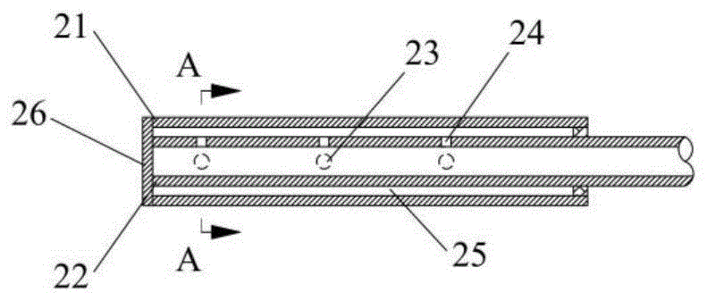
图3为根据本发明的一个示例性实施例的布风装置设置在炉膛内的示意图,图4A-4D分别示出了根据本发明的一个示例性实施例的布风装置的纵截面图、横截面图、外管和内管。Fig. 3 is a schematic diagram of an air distribution device according to an exemplary embodiment of the present invention arranged in a furnace, and Figs. 4A-4D respectively show a longitudinal sectional view, a transverse cross-sectional view of the air distribution device according to an exemplary embodiment of the present invention Sectional view, outer and inner tubes.
如图3所示,布风装置2为风管型式,水平布置在流化床炉膛1的底部,风管侧壁开有通孔,风管上不设置风帽。风管可根据布风需要设置多排,每根风管上的通孔可根据布风需要进行布置。在设置多排的情况下,可以在多排布风装置或者布风管之间形成排渣通道。As shown in FIG. 3 , the
布风装置2的内部结构示例性的如图4A-4D所示。布风装置2包括外管21和内管22,二管之间限定一环缝25(该环缝对应于布风空间),外管21和内管22一端共同由盲板26封闭,外管21另一端封闭于内管22侧壁,内管22的另一端为流化气体入口,与流化气体气源(未示出)连通。The internal structure of the
在穿过内管22中心线的水平面以上的内管壁上开有内管通孔24。在穿过外管中心线的水平面或以下的外管壁开有外管通孔23,在如图所示的实施例中,外管通孔23布置在穿过外管中心线的水平面上。虽然没有示出,外管通孔23也可以布置在外管的中心线的水平面以上。An inner tube through
如图4A-4D所示,外管21在同一横截面上的外管通孔23数量不小于2,如图4B所示,外管通孔23以y轴(对应于穿过外管的中心轴线的竖直面)为对称轴对称分布,外管通孔23位于x轴(对应于穿过外管的中心轴线的水平面)所在的水平面。如前面提及的,外管通孔23也可以位于x轴的下方或上方且与y轴方向的角度α为0~±90°。在图4A所示的结构中,内管22的内管通孔24数量不小于1,在图4B所示的横截面中,内管通孔24与竖直方向的y轴角度重合,在图4B所示的实施例中,内管通孔24位于x轴上方。但是,如能够理解的,内管通孔24与竖直方向的y轴角度还可为0~±90°,例如,内管通孔24可以位于x轴下方。As shown in FIGS. 4A-4D , the number of the outer tube through
外管21在同一横截面上的外管通孔23为一组,可沿轴向布置多组,换言之,外管通孔24可以包括至少一列外管通孔,该列外管通孔可以沿外管的轴向排布;内管22在同一横截面上的内管通孔24为一组,可沿轴向布置多组,换言之,所述内管通孔包括至少一列内管通孔,该列内管通孔可以沿内管的轴向排布。The outer tube through
在图4A-4D所示的实施例中,每组外管通孔23和内管通孔24沿轴向一一对齐,换言之,内管通孔和对应的外管通孔在轴向方向上的位置相同。In the embodiment shown in FIGS. 4A-4D , each set of outer tube through
如图4A所示,内管22与外管21同轴布置,但是如能够理解的,两者也可以非同轴布置,均在本发明的保护范围之内。As shown in FIG. 4A , the
如图7所示,布风装置上还可以设置罩部,所述罩部具有外凸的弧形顶部或三角形顶部,所述罩部支撑在或者覆盖所述外管的上侧部分。如此,罩部可以保护布风管,也可以尽量减少床料在布风管上堆积,还可以提高布风管的强度。As shown in FIG. 7 , a cover part may be further provided on the air distribution device, the cover part has a convex arc top or a triangular top, and the cover part is supported on or covers the upper part of the outer pipe. In this way, the cover part can protect the air distribution pipe, can also minimize the accumulation of bed material on the air distribution pipe, and can also improve the strength of the air distribution pipe.
下面示例性说明图4A-4D所示的布风装置或布风管的布风原理。The air distribution principle of the air distribution device or the air distribution duct shown in FIGS. 4A-4D is exemplarily described below.
流化气体从气源进入内管22,通过内管通孔24进入环缝25或布风空间,在环缝中经过流态调整后通过外管通孔23流出进入炉膛1,实现流化作用。The fluidizing gas enters the
本技术方案具有防止床料反蹿至布风装置内部的技术效果,具体说明如下:当流化状态发生波动时,炉膛1内的流化气体可能夹带床料穿过外管21上的外管通孔23进入环缝25,由于环缝25的流通面积大于外管通孔23的流通面积,反蹿的气体进入环缝25后流速瞬间下降,无法继续携带床料继续流动到达内管22上的内管通孔24,也就无法穿过内管通孔24进入内管22。当流化状态恢复正常时,流化气体即可逐渐将环缝25中的床料携带通过外管通孔23流出布风装置外管21。This technical solution has the technical effect of preventing the bed material from jumping back into the air distribution device. The specific explanation is as follows: when the fluidization state fluctuates, the fluidizing gas in the
本发明提供的一体化布风装置结构简单,具有加工制造、维护维修简单的技术效果。本装置的外管(21)和内管(22)均可以使用标准规格的厚壁钢管直接加工而成,材质为耐磨损耐高温钢材。根据布风参数在两管上进行开孔再进行组装即可完成布风装置的加工。每根布风管上可以开多组通孔,每组通孔可以起到现有技术中1个风帽的作用,其加工复杂程度远低于风帽。本装置的通孔一旦发生损坏,只需重新钻孔或修补即可,维修简单。The integrated air distribution device provided by the invention has a simple structure, and has the technical effects of simple manufacturing, maintenance and repair. Both the outer pipe (21) and the inner pipe (22) of the device can be directly processed by thick-walled steel pipes of standard specifications, and the material is wear-resistant and high-temperature-resistant steel. According to the air distribution parameters, the two pipes are opened and then assembled to complete the processing of the air distribution device. Multiple groups of through holes can be opened on each air distribution pipe, and each group of through holes can function as a hood in the prior art, and the processing complexity is much lower than that of the hood. Once the through hole of the device is damaged, it only needs to be re-drilled or repaired, and the maintenance is simple.
本发明提供的布风装置为一体化布风装置,有别于现有技术中的“风室/风管+风帽”的结构,取消了风帽,简化了布风结构,从而避免了风帽结构的缺点,消除了强度较为薄弱的位置,具有不易损坏的技术效果。因为取消了风帽,所以彻底避免了风帽脱落的风险;根据本发明的布风装置主要结构是外管21和内管22,这可以是两根钢管,本身较现有技术的风帽尺寸更大,强度更高,不易损坏。根据本发明的布风装置的外管21可采用耐磨损耐高温钢材,焊接位置仅有端盖以及内外管联接处等少数位置,强度薄弱位置很少。此外,内管22嵌套于外管21内部,磨损较小;且流化气体流过管中时可起到冷却作用,高温损坏的风险也较小。The air distribution device provided by the present invention is an integrated air distribution device, which is different from the structure of "air chamber/air duct + air cap" in the prior art. The disadvantage is that it eliminates the weaker position, and has the technical effect of not being easily damaged. Because the hood is cancelled, the risk of the hood falling off is completely avoided; the main structure of the air distribution device according to the present invention is the
本发明提供的一体化布风装置,采用风管结构,在用于流化床锅炉炉膛等部件中时,与现有技术采用的风室相比尺寸大大缩小,具有排渣方便、不易变形的技术效果。本发明的布风装置采用风管型式,可使用一排并列布置风管实现与风室上布置大量风帽相同的布风效果。但风管的尺寸较风室小很多,因此在高温运行时变形较小。另外当流化床产生炉渣时,可以从风管之间的空间穿过,再在风管下方布置排渣装置排出,排渣更为方便彻底。The integrated air distribution device provided by the present invention adopts an air duct structure, and when used in components such as a fluidized bed boiler furnace, the size is greatly reduced compared with the air chamber adopted in the prior art, and it has the advantages of convenient slag discharge and not easy to deform. technical effect. The air distribution device of the present invention adopts an air duct type, and can use a row of parallel air ducts to achieve the same air distribution effect as arranging a large number of air caps on the air chamber. However, the size of the air duct is much smaller than that of the air chamber, so there is less deformation during high temperature operation. In addition, when the fluidized bed produces slag, it can pass through the space between the air ducts, and then arrange a slag discharge device under the air duct to discharge, so that the slag discharge is more convenient and thorough.
图5为根据本发明的一个示例性实施例的布风装置的结构示意图。图5所示的布风装置的结构与图4A-4D所示的结构的区别在于,在图5中,外管通孔23和内管通孔24并不沿轴向对齐(即在轴向方向上的处于相同的位置,例如距离外管的盲端具有相同的轴向距离),而是存在一定偏移。该布置方式具有布风更加均匀、防止床料反蹿能力更强的技术效果。由于内外管通孔交错布置,流化气体从内管22穿过内管通孔24进入环缝25后,不会立刻穿过外管通孔23流出,而是在环缝25中实现一定整流后再穿过外管通孔23流出,因此其总体布风更加均匀。另外,由于内管通孔和外管通孔交错布置,当流化状态发生波动时,可能发生炉膛1内的流化气体夹带床料穿过外管21上的外管通孔23进入环缝25的情形,但由于环缝25的流通面积大于外管通孔23的流通面积,反蹿的气体进入环缝25后流速瞬间下降,且由于外管通孔与内管通孔有一定距离,穿过外管通孔23的流化气体及其携带的床料将更难到达内管通孔24并穿过内管通孔24进入内管22。因此,图5所示的布风装置的防止床料反蹿效果更好。FIG. 5 is a schematic structural diagram of an air distribution device according to an exemplary embodiment of the present invention. The difference between the structure of the air distribution device shown in FIG. 5 and the structure shown in FIGS. 4A-4D is that, in FIG. 5 , the outer tube through
图6为根据本发明的另一个示例性实施例的布风装置的结构示意图。图6所示的布风装置的结构与图4A-4D所示的结构的区别在于,在图6中,内管22不在管侧壁开孔,内管22远离流化气体源、朝向外管21内部的一端(即插入到外管21内的一端)不与外管21的盲板接触和连接,并且设置为开口端,开口27代替内管通孔,将流化风送入环缝25。该布置方式也具有布风均匀、防床料反蹿的技术效果,同时因为不需要内管22上加工内管通孔24,因此结构更加简单,加工和安装更加方便。如能够理解的,图6所示的结构中,内管上也可以设置内管通孔,这也在本发明的保护范围之内。FIG. 6 is a schematic structural diagram of an air distribution device according to another exemplary embodiment of the present invention. The difference between the structure of the air distribution device shown in FIG. 6 and the structure shown in FIGS. 4A-4D is that, in FIG. 6 , the
基于以上,本发明提出了如下技术方案:Based on the above, the present invention proposes the following technical solutions:
1、一种布风装置,包括:1. An air distribution device, comprising:
外管,外管的第一端为盲端;The outer tube, the first end of the outer tube is a blind end;
内管,内管的第一端位于外管内,内管的第二端位于外管之外,外管的第二端闭合连接到内管的外壁,内管的第二端适于与气体源相通,The inner tube, the first end of the inner tube is located in the outer tube, the second end of the inner tube is located outside the outer tube, the second end of the outer tube is closed and connected to the outer wall of the inner tube, and the second end of the inner tube is suitable for connecting with the gas source connected,
其中:in:
内管与外管之间形成有布风空间,内管在外管内的部分设置有与所述布风空间相通的第一通道,外管设置有贯穿外管的侧壁的第二通道。An air distribution space is formed between the inner tube and the outer tube, the part of the inner tube inside the outer tube is provided with a first channel communicating with the air distribution space, and the outer tube is provided with a second channel penetrating the side wall of the outer tube.
2、根据1所述的布风装置,其中:2. The air distribution device according to 1, wherein:
所述内管的第一端闭合或者由外管的盲端的内壁闭合。The first end of the inner tube is closed or closed by the inner wall of the blind end of the outer tube.
3、根据1所述的布风装置,其中:3. The air distribution device according to 1, wherein:
所述内管的第一端为开口端且与外管的盲端的内壁在轴向方向上间隔开,所述第一通道包括所述内管的第一端的开口端。The first end of the inner tube is an open end and is axially spaced from the inner wall of the blind end of the outer tube, and the first passage includes the open end of the first end of the inner tube.
4、根据2或3所述的布风装置,其中:4. The air distribution device according to 2 or 3, wherein:
在所述布风空间内,在内管与外管之间设置有支撑结构,所述支撑结构用于保持所述内管。In the air distribution space, a support structure is provided between the inner tube and the outer tube, and the support structure is used to hold the inner tube.
5、根据2或3所述的布风装置,其中:5. The air distribution device according to 2 or 3, wherein:
所述第一通道包括贯穿所述内管的侧壁设置的多个内管通孔,所述第二通道包括贯穿外管的侧壁的多个外管通孔。The first channel includes a plurality of inner tube through holes arranged through the sidewall of the inner tube, and the second channel includes a plurality of outer tube through holes arranged through the sidewall of the outer tube.
6、根据2或3所述的布风装置,其中:6. The air distribution device according to 2 or 3, wherein:
在轴向方向上相邻的所述内管通孔和外管通孔的通孔轴线彼此成角度。The through-hole axes of the inner tube through-holes and the outer tube through-holes adjacent in the axial direction are angled to each other.
7、根据6所述的布风装置,其中:7. The air distribution device according to 6, wherein:
在轴向方向上相邻的所述内管通孔和外管通孔在轴向方向上的位置错开;或者The positions of the adjacent inner tube through holes and outer tube through holes in the axial direction are staggered in the axial direction; or
至少一个内管通孔和对应的外管通孔在轴向方向上的位置相同。The positions of at least one inner tube through hole and the corresponding outer tube through hole in the axial direction are the same.
8、根据6所述的布风装置,其中:8. The air distribution device according to 6, wherein:
所述内管通孔包括至少一列内管通孔;The inner tube through holes include at least one row of inner tube through holes;
所述外管通孔包括至少一列外管通孔。The outer tube through holes include at least one row of outer tube through holes.
9、根据8所述的布风装置,其中:9. The air distribution device according to 8, wherein:
所述内管通孔包括沿内管的轴向排布的一列内管通孔,所述外管通孔包括沿外管的轴向排布而布置在外管的直径方向上的两侧的两列外管通孔,所述一列内管通孔与内管的轴线所限定的平面与所述两列外管通孔所限定的平面彼此垂直。The inner tube through holes include a row of inner tube through holes arranged along the axial direction of the inner tube, and the outer tube through holes include two outer tube through holes arranged along the axial direction of the outer tube and arranged on both sides in the diameter direction of the outer tube. A row of outer tube through holes, the plane defined by the one row of inner tube through holes and the axis of the inner tube and the plane defined by the two rows of outer tube through holes are perpendicular to each other.
10、根据9所述的布风装置,其中:10. The air distribution device according to 9, wherein:
所述两列外管通孔处于水平面。The two rows of outer tube through holes are in a horizontal plane.
11、根据1-3中任一项所述的布风装置,还包括:11. The air distribution device according to any one of 1-3, further comprising:
罩部,所述罩部具有外凸的弧形顶部或三角形顶部,所述罩部支撑在或者覆盖所述外管的上侧部分。A cover part, the cover part has a convex arc top or a triangular top, the cover part supports or covers the upper side part of the outer tube.
12、根据1-3中任一项所述的布风装置,其中:12. The air distribution device according to any one of 1-3, wherein:
所述内管与外管的同轴布置。The inner and outer tubes are arranged coaxially.
13、一种流化系统,包括:13. A fluidization system comprising:
流化空间;和fluidized space; and
根据1-12中任一项所述的布风装置,所述布风装置的第二通道与所述流化空间相通。According to the air distribution device according to any one of 1-12, the second channel of the air distribution device communicates with the fluidization space.
14、根据13所述的流化系统,其中:14. The fluidization system of 13, wherein:
所述流化系统为循环流化床锅炉,或者所述流化系统为返料器。The fluidization system is a circulating fluidized bed boiler, or the fluidization system is a return feeder.
15、根据13或14所述的流化系统,其中:15. A fluidized system according to 13 or 14, wherein:
所述流化系统包括多个并排水平布置的布风装置,并排布置的布风装置之间彼此间隔开。The fluidization system includes a plurality of air distribution devices arranged side by side and horizontally, and the air distribution devices arranged side by side are spaced apart from each other.
16、一种固体物料处理设备,包括根据13-15中任一项所述的流化系统,或者根据1-12中任一项所述的布风装置。16. A solid material processing equipment, comprising the fluidization system according to any one of 13-15, or the air distribution device according to any one of 1-12.
基于本发明的技术方案,至少可以获得如下技术效果之一:Based on the technical solution of the present invention, at least one of the following technical effects can be obtained:
a、根据本发明的布风装置的主体结构由内管和外管形成,其结构简单,具有加工制造、维护维修简单的技术效果。a. The main structure of the air distribution device according to the present invention is formed by an inner tube and an outer tube, the structure is simple, and has the technical effect of simple manufacturing, maintenance and repair.
b、根据本发明的布风装置取消了风帽,消除了因为设置风帽导致的强度较为薄弱的位置,具有不易损坏的技术效果。b. The air distribution device according to the present invention cancels the hood, and eliminates the weak position caused by the hood, and has the technical effect of not being easily damaged.
c、根据本发明的布风装置采用风管结构,在用于流化床锅炉炉膛等部件中时,与现有技术采用的风室相比尺寸大大缩小,具有排渣方便、不易变形的技术效果。c. The air distribution device according to the present invention adopts an air duct structure, and when used in components such as a fluidized bed boiler furnace, the size is greatly reduced compared with the air chamber adopted in the prior art, and it has the technology of convenient slag discharge and not easy to deform Effect.
尽管已经示出和描述了本发明的实施例,对于本领域的普通技术人员而言,可以理解在不脱离本发明的原理和精神的情况下可以对这些实施例进行变化、要素组合,本发明的范围由所附权利要求及其等同物限定。Although the embodiments of the present invention have been shown and described, it will be understood by those of ordinary skill in the art that The scope is defined by the appended claims and their equivalents.
Claims (16)
Priority Applications (1)
| Application Number | Priority Date | Filing Date | Title |
|---|---|---|---|
| CN202010724608.4A CN111780098B (en) | 2020-07-24 | 2020-07-24 | Air distribution device, combustion system and solid material treatment equipment |
Applications Claiming Priority (1)
| Application Number | Priority Date | Filing Date | Title |
|---|---|---|---|
| CN202010724608.4A CN111780098B (en) | 2020-07-24 | 2020-07-24 | Air distribution device, combustion system and solid material treatment equipment |
Publications (2)
| Publication Number | Publication Date |
|---|---|
| CN111780098A true CN111780098A (en) | 2020-10-16 |
| CN111780098B CN111780098B (en) | 2024-05-10 |
Family
ID=72763319
Family Applications (1)
| Application Number | Title | Priority Date | Filing Date |
|---|---|---|---|
| CN202010724608.4A Active CN111780098B (en) | 2020-07-24 | 2020-07-24 | Air distribution device, combustion system and solid material treatment equipment |
Country Status (1)
| Country | Link |
|---|---|
| CN (1) | CN111780098B (en) |
Cited By (2)
| Publication number | Priority date | Publication date | Assignee | Title |
|---|---|---|---|---|
| CN112830686A (en) * | 2021-01-21 | 2021-05-25 | 四川虹科创新科技有限公司 | Device and method for controlling sulfur film on surface of float glass |
| CN116768460A (en) * | 2023-07-05 | 2023-09-19 | 索奥斯(广东)玻璃技术股份有限公司 | Glass tempering production line using convection air distribution structure |
Citations (6)
| Publication number | Priority date | Publication date | Assignee | Title |
|---|---|---|---|---|
| JP2001280624A (en) * | 2000-03-31 | 2001-10-10 | Babcock Hitachi Kk | Incombustible deposition prevention apparatus in fluidized bed |
| JP2008008575A (en) * | 2006-06-30 | 2008-01-17 | Mitsubishi Heavy Ind Ltd | Air nozzle structure of fluidized bed combustion furnace |
| CN102563629A (en) * | 2010-12-15 | 2012-07-11 | 中国科学院工程热物理研究所 | Spiral-flow type built-in cylindrical blast cap |
| CN103423739A (en) * | 2013-07-30 | 2013-12-04 | 中国华能集团清洁能源技术研究院有限公司 | Abrasion proof slag-leakage resistant wind cap with combined core tube |
| CN106702537A (en) * | 2016-12-21 | 2017-05-24 | 湖南顶立科技有限公司 | Air distributor and preoxidation furnace hot air circulating system |
| CN207247189U (en) * | 2017-09-12 | 2018-04-17 | 中科清能燃气技术(北京)有限公司 | Novel anti-blockage blast cap |
-
2020
- 2020-07-24 CN CN202010724608.4A patent/CN111780098B/en active Active
Patent Citations (6)
| Publication number | Priority date | Publication date | Assignee | Title |
|---|---|---|---|---|
| JP2001280624A (en) * | 2000-03-31 | 2001-10-10 | Babcock Hitachi Kk | Incombustible deposition prevention apparatus in fluidized bed |
| JP2008008575A (en) * | 2006-06-30 | 2008-01-17 | Mitsubishi Heavy Ind Ltd | Air nozzle structure of fluidized bed combustion furnace |
| CN102563629A (en) * | 2010-12-15 | 2012-07-11 | 中国科学院工程热物理研究所 | Spiral-flow type built-in cylindrical blast cap |
| CN103423739A (en) * | 2013-07-30 | 2013-12-04 | 中国华能集团清洁能源技术研究院有限公司 | Abrasion proof slag-leakage resistant wind cap with combined core tube |
| CN106702537A (en) * | 2016-12-21 | 2017-05-24 | 湖南顶立科技有限公司 | Air distributor and preoxidation furnace hot air circulating system |
| CN207247189U (en) * | 2017-09-12 | 2018-04-17 | 中科清能燃气技术(北京)有限公司 | Novel anti-blockage blast cap |
Non-Patent Citations (1)
| Title |
|---|
| 朱佳琪: "《管式布风流化床的流动特性研究及其处理固体废物的工业化应用》", 《工程科技Ⅰ辑》 * |
Cited By (2)
| Publication number | Priority date | Publication date | Assignee | Title |
|---|---|---|---|---|
| CN112830686A (en) * | 2021-01-21 | 2021-05-25 | 四川虹科创新科技有限公司 | Device and method for controlling sulfur film on surface of float glass |
| CN116768460A (en) * | 2023-07-05 | 2023-09-19 | 索奥斯(广东)玻璃技术股份有限公司 | Glass tempering production line using convection air distribution structure |
Also Published As
| Publication number | Publication date |
|---|---|
| CN111780098B (en) | 2024-05-10 |
Similar Documents
| Publication | Publication Date | Title |
|---|---|---|
| CN111780098A (en) | Air distribution units, combustion systems and solid material handling equipment | |
| US20080271657A1 (en) | Coal fired process heaters | |
| CN111706856B (en) | Biased Return Control for High Temperatures | |
| US20160290632A1 (en) | Fluidized Bed Apparatus | |
| US20160356488A1 (en) | Fluidized Bed Apparatus and its Components | |
| CN104566977B (en) | Conduction oil heating furnace with dual fluidized beds | |
| CN202973073U (en) | Air-cooled slag discharging pipe for small and medium-sized circulating fluidized bed boiler | |
| CN109576436B (en) | Forced circulation cooling flue | |
| CN212132414U (en) | A fluidized bed boiler air cap | |
| CN106439799A (en) | Air distribution structure of circulating fluidized bed boiler | |
| CA2587869C (en) | Sncr distribution grid | |
| CN105180160A (en) | Combustion device for reducing nitrogen oxide emission in circulating fluidized bed | |
| CN112010041B (en) | Material conveying cooling device | |
| US20170016616A1 (en) | Fluidized Bed Heat Exchanger | |
| CN205807394U (en) | There is the CFBC equipment of Even air distribution device | |
| US5575086A (en) | Fluidized bed with improved nozzle construction | |
| CN216790886U (en) | Treatment furnace and combined cooling equipment for high-temperature materials | |
| CN117146272A (en) | Radiant inner tube and radiant tube | |
| CN110207513B (en) | Ash cooler and waste heat utilization system | |
| CN114136104A (en) | Treatment furnace and combined cooling equipment for high-temperature materials | |
| CN223021011U (en) | A solid particle cooler | |
| CN207763557U (en) | A kind of heat-exchanging component and the fluidized-bed reactor comprising it | |
| TWI789359B (en) | Tangentially fired boiler and method of operating a tangentially fired boiler | |
| CN107255421B (en) | High-temperature powder heat exchanger | |
| CN207455915U (en) | Water-coal-slurry organic heat carrier accumulatingdust convection tube structure |
Legal Events
| Date | Code | Title | Description |
|---|---|---|---|
| PB01 | Publication | ||
| PB01 | Publication | ||
| SE01 | Entry into force of request for substantive examination | ||
| SE01 | Entry into force of request for substantive examination | ||
| GR01 | Patent grant | ||
| GR01 | Patent grant |