CN1117608C - Membrane moudle for a membrane sparation system, its use and process for producing the same - Google Patents
Membrane moudle for a membrane sparation system, its use and process for producing the same Download PDFInfo
- Publication number
- CN1117608C CN1117608C CN97191603A CN97191603A CN1117608C CN 1117608 C CN1117608 C CN 1117608C CN 97191603 A CN97191603 A CN 97191603A CN 97191603 A CN97191603 A CN 97191603A CN 1117608 C CN1117608 C CN 1117608C
- Authority
- CN
- China
- Prior art keywords
- filter membrane
- tubulose
- membrane component
- tubulose filter
- header
- Prior art date
- Legal status (The legal status is an assumption and is not a legal conclusion. Google has not performed a legal analysis and makes no representation as to the accuracy of the status listed.)
- Expired - Fee Related
Links
- 239000012528 membrane Substances 0.000 title claims abstract description 255
- 238000000034 method Methods 0.000 title description 8
- 230000008569 process Effects 0.000 title description 4
- 239000000203 mixture Substances 0.000 claims abstract description 28
- 238000012423 maintenance Methods 0.000 claims description 9
- 238000000926 separation method Methods 0.000 claims description 7
- 230000008676 import Effects 0.000 claims description 6
- ZZUFCTLCJUWOSV-UHFFFAOYSA-N furosemide Chemical compound C1=C(Cl)C(S(=O)(=O)N)=CC(C(O)=O)=C1NCC1=CC=CO1 ZZUFCTLCJUWOSV-UHFFFAOYSA-N 0.000 claims description 5
- 239000007788 liquid Substances 0.000 claims description 4
- 238000004804 winding Methods 0.000 claims description 4
- 238000009295 crossflow filtration Methods 0.000 claims description 3
- 238000001914 filtration Methods 0.000 claims description 3
- 238000007789 sealing Methods 0.000 claims description 3
- 239000007787 solid Substances 0.000 abstract description 2
- 239000012530 fluid Substances 0.000 description 42
- 230000000149 penetrating effect Effects 0.000 description 41
- 238000010586 diagram Methods 0.000 description 10
- 238000005452 bending Methods 0.000 description 7
- 238000002156 mixing Methods 0.000 description 7
- 238000010926 purge Methods 0.000 description 5
- 230000000712 assembly Effects 0.000 description 4
- 238000000429 assembly Methods 0.000 description 4
- 230000002349 favourable effect Effects 0.000 description 4
- 239000000463 material Substances 0.000 description 4
- 230000009183 running Effects 0.000 description 4
- 239000002184 metal Substances 0.000 description 3
- 239000000047 product Substances 0.000 description 3
- 125000006850 spacer group Chemical group 0.000 description 3
- 241001672694 Citrus reticulata Species 0.000 description 2
- 241000196324 Embryophyta Species 0.000 description 2
- 230000008901 benefit Effects 0.000 description 2
- 230000015572 biosynthetic process Effects 0.000 description 2
- 230000008859 change Effects 0.000 description 2
- 238000004140 cleaning Methods 0.000 description 2
- 238000010276 construction Methods 0.000 description 2
- 238000001125 extrusion Methods 0.000 description 2
- 238000011010 flushing procedure Methods 0.000 description 2
- 235000015203 fruit juice Nutrition 0.000 description 2
- 230000012447 hatching Effects 0.000 description 2
- 229910010272 inorganic material Inorganic materials 0.000 description 2
- 239000011147 inorganic material Substances 0.000 description 2
- 239000011368 organic material Substances 0.000 description 2
- 239000012466 permeate Substances 0.000 description 2
- 239000004033 plastic Substances 0.000 description 2
- 229920003023 plastic Polymers 0.000 description 2
- 238000005245 sintering Methods 0.000 description 2
- 229940037003 alum Drugs 0.000 description 1
- 230000000740 bleeding effect Effects 0.000 description 1
- 230000001413 cellular effect Effects 0.000 description 1
- 239000011248 coating agent Substances 0.000 description 1
- 238000000576 coating method Methods 0.000 description 1
- 150000001875 compounds Chemical class 0.000 description 1
- 239000012141 concentrate Substances 0.000 description 1
- 238000005315 distribution function Methods 0.000 description 1
- 230000000694 effects Effects 0.000 description 1
- 239000005357 flat glass Substances 0.000 description 1
- 235000013305 food Nutrition 0.000 description 1
- 235000011389 fruit/vegetable juice Nutrition 0.000 description 1
- 238000007689 inspection Methods 0.000 description 1
- 238000009434 installation Methods 0.000 description 1
- 238000004519 manufacturing process Methods 0.000 description 1
- 230000008520 organization Effects 0.000 description 1
- 239000002245 particle Substances 0.000 description 1
- 230000002093 peripheral effect Effects 0.000 description 1
- 230000001105 regulatory effect Effects 0.000 description 1
- 238000001223 reverse osmosis Methods 0.000 description 1
- 239000008247 solid mixture Substances 0.000 description 1
- 230000007704 transition Effects 0.000 description 1
- 239000002351 wastewater Substances 0.000 description 1
- 238000003466 welding Methods 0.000 description 1
- 238000009736 wetting Methods 0.000 description 1
Images


Classifications
-
- B—PERFORMING OPERATIONS; TRANSPORTING
- B01—PHYSICAL OR CHEMICAL PROCESSES OR APPARATUS IN GENERAL
- B01D—SEPARATION
- B01D63/00—Apparatus in general for separation processes using semi-permeable membranes
- B01D63/06—Tubular membrane modules
- B01D63/068—Tubular membrane modules with flexible membrane tubes
-
- B—PERFORMING OPERATIONS; TRANSPORTING
- B01—PHYSICAL OR CHEMICAL PROCESSES OR APPARATUS IN GENERAL
- B01D—SEPARATION
- B01D63/00—Apparatus in general for separation processes using semi-permeable membranes
- B01D63/02—Hollow fibre modules
-
- B—PERFORMING OPERATIONS; TRANSPORTING
- B01—PHYSICAL OR CHEMICAL PROCESSES OR APPARATUS IN GENERAL
- B01D—SEPARATION
- B01D63/00—Apparatus in general for separation processes using semi-permeable membranes
- B01D63/02—Hollow fibre modules
- B01D63/025—Bobbin units
-
- B—PERFORMING OPERATIONS; TRANSPORTING
- B01—PHYSICAL OR CHEMICAL PROCESSES OR APPARATUS IN GENERAL
- B01D—SEPARATION
- B01D63/00—Apparatus in general for separation processes using semi-permeable membranes
- B01D63/02—Hollow fibre modules
- B01D63/04—Hollow fibre modules comprising multiple hollow fibre assemblies
- B01D63/043—Hollow fibre modules comprising multiple hollow fibre assemblies with separate tube sheets
-
- B—PERFORMING OPERATIONS; TRANSPORTING
- B01—PHYSICAL OR CHEMICAL PROCESSES OR APPARATUS IN GENERAL
- B01D—SEPARATION
- B01D69/00—Semi-permeable membranes for separation processes or apparatus characterised by their form, structure or properties; Manufacturing processes specially adapted therefor
- B01D69/04—Tubular membranes
-
- B—PERFORMING OPERATIONS; TRANSPORTING
- B01—PHYSICAL OR CHEMICAL PROCESSES OR APPARATUS IN GENERAL
- B01D—SEPARATION
- B01D69/00—Semi-permeable membranes for separation processes or apparatus characterised by their form, structure or properties; Manufacturing processes specially adapted therefor
- B01D69/08—Hollow fibre membranes
-
- B—PERFORMING OPERATIONS; TRANSPORTING
- B01—PHYSICAL OR CHEMICAL PROCESSES OR APPARATUS IN GENERAL
- B01D—SEPARATION
- B01D2313/00—Details relating to membrane modules or apparatus
- B01D2313/06—External membrane module supporting or fixing means
-
- B—PERFORMING OPERATIONS; TRANSPORTING
- B01—PHYSICAL OR CHEMICAL PROCESSES OR APPARATUS IN GENERAL
- B01D—SEPARATION
- B01D2313/00—Details relating to membrane modules or apparatus
- B01D2313/14—Specific spacers
Abstract
The membrane module includes tube membranes (6), which are arranged in the membrane module in coiled, curved form (8). As a result, a greater total membrane surface area per unit of volume, simplified assembly, and processing of material mixtures with a high solid proportion are all attained.
Description
The present invention relates to the filter membrane component of a kind of cross flow filtration equipment that a kind of filter membrane separating mixture of being made up of one or more tubulose filter membranes uses.
As everyone knows, this filter membrane component is the structural detail of cross flow filter equipment.This equipment generally includes a plurality of tubulose filter membranes with filter effect.This tubulose filter membrane makes antipriming pipe, this antipriming pipe or itself makes membrane filter, or has the filter membrane that is made by the organic or inorganic material on its surface.As everyone knows, filter membrane has the tubulose filter membrane that is positioned at inside or outside, and its interior diameter is that a few tenths of millimeter is to 100 millimeter.
For the filter efficiency situation in practicality is issued to supportable structure length of filter membrane component, a small amount of or a large amount of straight tubulose filter membranes is installed in a straight containing pipe.This compound tube has one as whole tubulose filter membranes of the medium to be filtered of residue shared entrance and exit and one or two outlet as the filtered fluid of penetrating fluid.
Also have some filter membrane components to make so-called winding assembly, the filter membrane of textile-like is wound into a long volume, and residue can circulate in this volume and penetrating fluid can flow out by thin elastomeric pad or the net that is involved in.This winding assembly is being very economical aspect its filter efficiency, but is not suitable for the very high mixture of separate solid composition owing to it is easy to stop up.In addition, be that several millimeters tubulose filter membrane also can be handled for example press juice of the high mixture of solid state component with interior diameter, and do not have stop up dangerous.
Because the filter efficiency of the unit are of the known tubulose filter membrane that poly-alum of usefulness or Kynoar (PDVF) are made is quite low, so in order to reach the filter efficiency that is suitable for of less expensive, must become a filter plant with a plurality of assembly serial or parallel connections, each assembly comprises for example each 19 tubulose filter membrane of 3 meters long.
If the number of series component is more, for example every string reaches about 16 assemblies, and then these assemblies interconnect by the elbow of 180 degree.If one group of group system or passage that includes only 5 parallel runnings simultaneously then must be with unit of the compact as far as possible composition of 80 assemblies, to reach about 180 meters
2The filter membrane area.For this reason, single component will be bearing on the cantilever of support and the tube connector of a large amount of residue side and sepage side is set.At this moment following problem can appear:
-each filter membrane component needs 4 pipe joints and 2 to 3 bearings that are bearing on the cantilever.When forming a filter plant with 80 assemblies, these tube connectors just need 80 connecting bends, 85 flexible pipes to be connected and 320 tube connectors with bearing, that is cost of equipment is too high, thereby reduce the economy of equipment.
-filter membrane has only the limited life-span.So filter membrane component is a consumable accessory, change in must be at certain time intervals.
So the installation and removal expense of this structure and complicated construction expenditure are very large.
So the objective of the invention is to address the above problem comprehensively.
According to the present invention, a kind of filter membrane component of described that class during to beginning, this purpose is achieved in that to be that the tubulose filter membrane is arranged to filter membrane component with the form of bending.A kind of favourable scheme of this filter membrane component has such feature, and promptly the tubulose filter membrane is arranged to filter membrane component with the form of reeling.
Wherein may have such characteristics, promptly the tubulose filter membrane is reversed into a branch of at least form by a plurality of tubulose filter membranes with rope form and is wound into filter membrane component.
Industry can realize layout of the present invention to show with known tubulose filter membrane, and these tubulose filter membranes can carry out bending by the bending radius less than 20 times bore, and do not damage filter membranous layer.Can buy required for this reason length from the market with the tubulose filter membrane that organic material is made.With inorganic material for example the known tubulose filter membrane made of sintering metal can make the filter membrane that needs length to 1 meter long pipeline section by crooked, welding and coating with commercially available.
Compare with known filter membrane component, filter membrane component of the present invention has high arranging density and advantage of simple structure.Compare with the above-mentioned group with 80 filter membrane components, this organizes about 180 meters of having of available about 1.4 meters overall diameters and 1.4 meters structure heights
2The filter membrane component of the present invention of identical membrane type filter area replace.According to the structure difference, only need about 3 tube connectors just can replace above-mentioned 320 tube connectors.Wherein the membrane filter area of filter membrane component is made of 150 parallel filter membrane pipes that have 55 meters long respectively of about 7 millimeters interior diameters.
Describe several embodiments of the present invention in detail below in conjunction with the description of the drawings.Accompanying drawing is represented:
Fig. 1 a represents the vertical cross-section B-B of Fig. 1 b of a filter membrane component of the separatory the present invention of filter membrane;
The horizontal cross-section A-A of filter membrane component shown in Fig. 1 b presentation graphs 1a;
Fig. 2 a represents the partial cross section C-C shown in Fig. 2 b of the tubulose filter membrane header on circle top or the end;
The end view drawing of tubulose filter membrane header shown in Fig. 2 b presentation graphs 2a;
Fig. 3 represents the vertical cross-section of a kind of scheme of a filter membrane component of the separatory the present invention of filter membrane;
Fig. 4 a represents the vertical cross-section of separatory another scheme of filter membrane component of the present invention of filter membrane and a penetrating fluid case combination;
Part of horizontal cross section D-D shown in Fig. 4 a that Fig. 4 b represents to cut open by the tubulose filter membrane header on reel a circle top or the terminal;
Fig. 5 is illustrated in shown in Fig. 1 a that separates with pad between the tubulose filter membrane a branch of cross section of being made up of a plurality of tubulose filter membranes of the circle of reeling in the filter membrane component;
Fig. 6 represents the cross section cut open by the spacer element that forms one on a tubulose filter membrane;
Fig. 7 represents the perspective view by a scheme of the spacer element that forms one on a tubulose filter membrane;
Fig. 8 represents around the view of the spacer element of the wire-like of tubulose filter membrane winding;
Fig. 9 represents by a kind of shape of 3 tubulose filter membranes according to a unit of length coiled;
Figure 10 a only represents respectively the radial section of two discoid flattened roll pitch of the laps making with a continuous tubulose filter membrane;
The coiling schematic diagram of two-layer flattened roll pitch of the laps shown in Figure 10 b presentation graphs 10a;
Figure 11 represents the axial component cross section of tubulose filter membrane band level around a filter membrane component of axle;
Figure 12 represents that the tubulose filter membrane is set up in parallel the coiling schematic diagram of two circles of reeling in a filter membrane component;
Figure 13 represents to turn to the perspective view of a tubulose filter membrane of flat tube form;
Figure 14 represents to have the separatory filter membrane component of the present invention of filter membrane of the container of the material that a conduct separated;
Figure 15 represents to have a schematic diagram filter membrane component shown in Figure 14, that be used for a kind of equipment of mixture filter membrane separation;
Figure 16 represents a filter membrane component of the present invention around the vertically arranged a plurality of tubulose filter membranes compositions of axle;
Figure 17 a, 17b represent two views of a filter membrane component, and a plurality of tubulose filter membranes are arranged between the support plate of drawer form replaceably when this filter membrane component;
Figure 18 represents to have a filter membrane component of the present invention of a plurality of tubulose filter membranes, and this filter membrane component can be vertical and horizontally disposed with a turning device;
Figure 19 represents the side view of several tubulose filter membranes with its filter membrane component of the present invention that is arranged in juxtaposition around axle horizontal;
Figure 20 represents the axial view of filter membrane component shown in Figure 19;
Figure 21 a, 21b, 21c represent to have the different views of a filter membrane component of the present invention of a plurality of horizontally disposed tubulose filter membranes and a container that can roll away from;
Figure 22 represents that the disc type flattened roll pitch of the laps of only making with a continuous tubulose filter membrane is arranged in one and is used for supporting and changing the box-shaped vessel of reeling and enclosing;
Figure 23 a represents that the discoid flattened roll pitch of the laps of only being made by a continuous tubulose filter membrane has a support plate that is used for improving stability;
Figure 23 b, two kinds of schemes of support plate shown in the 23c presentation graphs 23a;
Figure 24 represents for the diameter that enlarges the circle of reeling and filter area and the schematic diagram of a discoid flattened roll pitch of the laps of bilayer making with two continuous tubulose filter membranes;
Figure 25 represents respectively three groups being made up of three tubulose filter membranes and the connection diagrams that have header between each group of using as mixing chamber;
Figure 26 a, 26b, 26c represent the detail drawing that a tubulose filter membrane with a header shown in Figure 17 connects fast;
Syndeton shown in Figure 27 presentation graphs 2a with the coiling bundle of the tubulose filter membrane of a header, wherein, a plurality of tubulose filter membrane end faces of equal length are arranged to stairstepping;
The beam splitting end face that Figure 28 represents to have the tubulose filter membrane of equal length is the interruption that the tubulose filter membrane coiling Shu Zuowei mixing chamber in the filter membrane component constitutes shown in Fig. 1 a that ladder arranges.
Fig. 1 a and Fig. 1 b represent the cross section of a filter membrane component respectively, and band vertically is wound in this filter membrane component around the tubulose filter membrane of axle.This filter membrane component comprises the container 1 of a sealing, this container by bottom 2 and sealing dress thereon but removable top 3 form.Especially as shown in Figure 1a, the header 4,5 of two many tubulose filter membranes 6 is introduced in 3 both sides, top.Can know from figure and to find out that the part of every header 4,5 is arranged in closed container 1.Tubulose filter membrane 6 constitutes a continuous bundle 7, and this bundle connects header 4,5, and with a kind of pitch of the laps 8 of bending be wound on one as support vertically on axle 9.
Fig. 2 a and 2b represent the partial cross section and the axial view of header 4 or 5 one ends.Can know as Fig. 2 a and to find out that many tubular filter membranes 6 have the cable shape that what is called beats with one and reverse bunchy 7.Its objective is that bundle 7 does not damage tubulose filter membrane 6 with the curved guide of form 8.Tubulose filter membrane 6 is fixing with a kind of mould material 10 cast in the end of header 4.
The fruit juice that mixture to be separated has for example squeezed flows into a header 4,5 under pressure, parallelly at this place streams many tubular filter membranes 6.On corresponding another root header 5 or 4, mixture is exported again as residue, in passing through the process of tubulose filter membrane 6, quite little particle diameter separates by filter membrane in a well-known manner and arrives in the cavity of container 1 as penetrating fluid or filter liquor like this, and this cavity surrounds pitch of the laps 8 by Fig. 1.
Penetrating fluid arrives the outlet 11 of separator as what header was used around axle 9 by the while from this cavity.As shown in Figure 1a, make dish around axle 9 in the bottom scope that it is used for supporting pitch of the laps 8.Outlet 11 is arranged on the top, so that the separation filter membrane of tubulose filter membrane 6 always keeps wetting.The whole coiling circle 8 of bundle 7 can be from bottom 2 dismountings of container 1, so that check with header 4,5 and 9.2 be provided with a window glass 12 in the bottom equally, so that monitor.In order to emit penetrating fluid, a closable dump valve 13 is arranged at the container bottom, and top is provided with a vent valve 14.
In filter membrane component scheme shown in Figure 3, the parts of corresponding function are continued to use the reference number that Fig. 1 a has illustrated.Be arranged on the bottom 2 of container 1 here as the header 4,5 of the tube connector of residue, 3 outlets 11 that are provided with a penetrating fluid on top.When on the circle 8 of reeling, carrying out maintenance work, only need here with penetrating fluid pipe of top 3 dismountings to outlet 11.The circle 8 of reeling is stable by a locking belt 17.Porose 15 around axle 9 ' be provided with, so that collect penetrating fluid.
Fig. 4 a represents the another kind of scheme of filter membrane component.The closed container 1 here ' make penetrating fluid case.Container 1 ' in, around axle 16 in a row and the many tubulose filter membranes 6 of close wind.These tubulose filter membranes 6 perpendicular to direction of principal axis import header 4 ' and 5 ' in, locate the same with scheme shown in Figure 3 parallel the streaming of these headers at this with Fig. 1 a, wherein tubulose filter membrane 6 need not reverse, thereby reaches the high arranging density of filter area in available space.In addition, header 4 ', 5 ' can keep little diameter be laterally to import because tubulose filter membrane 6 resembles the D-D of cross section shown in the 4b.
Fig. 4 b represent a kind of mould material 10 of tubulose filter membrane 6 usefulness ' be cast in header 5 ' in situation.Penetrating fluid from tubulose filter membrane 6 arrive containers 1 ', this container also has the function of the penetrating fluid case of forming one here.Container 1 ' below be provided with permeate flow outlet 11 '.Shown in Fig. 4 a, the circle 8 of reeling ' stable with fixed band 17.
Fig. 5 represents to be equivalent to a tube bank of the tubulose filter membrane 6 of Fig. 2 b axial view, and the position of tubulose filter membrane 6 is stable by fixed band 17 in this tube bank.Know from figure and find out that fixed band 17 is used as the pad between the tubulose filter membrane 6 simultaneously.The outlet of the penetrating fluid that flows out from tubulose filter membrane 6 is improved owing to fixed band 17 reticulates.
The another kind of possibility of between the tubulose filter membrane 6 of a coiling form, setting up appropriate intervals as shown in Figure 6, at this moment tubulose filter membrane 6 keeps the element 27 of the formation one of spacings to thicken along circumference.The element 27 of this maintenance spacing ' a scheme as shown in Figure 7, this element 27 ' extend axially in tubulose filter membrane 6 outsides.According to Fig. 8, the element 27 of this maintenance spacing " also can twine with the shape of metal wire around a tubulose filter membrane 6 twist.
Figure 10 a represents only to have two spiral wound circles 8 of two-layer tubulose filter membrane 6 ", so in the form of annular discs.These circles 8 of reeling " both sides be connected the header 4 of residue ', 5 ' on, these headers also can connect with similar other pitch of the laps that do not illustrate.Penetrating fluid can be collected by known mode around pitch of the laps 8.Figure 10 b represents a kind of pitch of the laps 8 " the pitch of the laps schematic diagram of tubulose filter membrane 6.With Fig. 1 a, 3 and the filter membrane component scheme of 4a relatively, the replaceable single pitch of the laps 8 of the version of Figure 10 a ", thus replaceable single tubulose filter membrane 6.For this reason, the metal tube particularly suitable of sintering.
What Figure 11 represented the tubulose filter membrane of reeling is positioned at a filter membrane component of horizontal level around axle.This filter membrane component also comprises a closed container 11 ", two efferent ducts 11 that input and output pipe 4 , 5 that this container has that residue uses and penetrating fluid are used ".Tubulose filter membrane or input and output pipe 4 that use as individual tubes or many parallel tube bank 7 ' connection residues and 5 are around trunnion axis 16 ' coiling.Keep by pad 30 in the pitch of the laps 8 " at container 1 ", in order to make pitch of the laps 8 " permeate flow to efferent duct 11 ", these pads are provided with passage.
Consider the maintenance of tubular assembly and to the different needs of filter area, a scheme of the filter membrane component in a container comprises at least two independent pitch of the laps that have the tubulose filter membrane 6 of the independent input and output of filter residue.Thisly be wound on schematic diagram that an independent coiling with axis 16 " jointly around body 9 " encloses 8 as shown in figure 12.
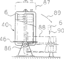
A scheme of the described filter membrane component of Fig. 4 a as shown in figure 14.Also be that the tubulose filter membrane 6 of a plurality of coilings that do not illustrate separately in the drawings is stacked mutually around a common axle 16 in this scheme.Tubulose filter membrane 6 here for example Figure 10 a to describe be to reel like this, mixture promptly to be separated imports header 5 " and 4 " and the mutual diametrically contraposition of these headers itself.In Fig. 4 a illustrated embodiment, the catch box 1 of penetrating fluid ' only by air bleeding valve 14 ' overflow pipe is connected with sepage case 18, the container 40 of Figure 14 tubulose filter membrane 6 is the container usefulness of the penetrating fluid that separated of conduct simultaneously then.
Penetrating fluid case 40 bottoms comprise the flow export 11 of a penetrating fluid ", these penetrating fluids are extracted out by the pump 41 of a connection.As shown in figure 15, in the separation equipment running, preferably only when penetrating fluid reaches maximum level 42, penetrating fluid just is extracted into a minimum liquid level 43 from penetrating fluid case 40 usefulness pumps.Penetrating fluid case 40 comprises a removable top 44, and this top is connected with bottom 45 by a dismountable flange 46.A closable inspection opening 47 is arranged at top 44, does not need to take down top 44 when carrying out maintenance work.At last, be provided with a purge joint 48, so that purge tubulose filter membrane 6 on sepage case 40 tops.
Figure 15 represents the schematic diagram of the separatory a kind of equipment of filter membrane, and this equipment comprises filter membrane component of the present invention 50 shown in Figure 14.In addition, this equipment comprises a case 51, and this case receives a kind of mixture to be separated 53 by a pipe 52.A delivery valve 54 that below case 51, connects mixture 53.This mixture is transported to the product inlet 58 of brave membrane module 50 by the control valve 57 of a pressure sensor 56 controls by a pump 55 and one.Except delivery valve 54, the transfer valve 59 of a flushing liquor also is set, this flushing liquor can replace in the mixture 53 input filter membrane components 50.
As Figure 14 describes, flow through filter membrane component 50 and leave filter membrane component as residue and arrive outlet 60 of mixture 53.Residue is got back to the case 51 by pipeline 61 and control valve 62 or through valve 63 from exporting 60, perhaps leaves the filter membrane separation equipment through valve 54.That is mixture 53 is in the device separates running, circulate in a residue loop.Described in Figure 14, the separator in the tubulose filter membrane 6 " leaves penetrating fluid case 40 and is siphoned away from equipment by the pump 41 of a connection through exporting 11 as penetrating fluid as.
The operation of pump 41 is controlled through control line 67 by the sensor 65,66 of the liquid level of the penetrating fluid in the penetrating fluid case 40, as shown in figure 14.In order to measure the pressure of mixture 53, a pressure sensor 68,69 is set respectively at product inlet 58 and outlet 60.The pressure of product inlet 58 is regulated by control valve 62, and this control valve obtains a pressure inverse signal from pressure sensor 68 through control line 70.
Figure 16 represents the organization plan of Figure 14 filter membrane component, in this scheme, continues to use the equal reference numbers of front corresponding construction element.Figure 16 represents being connected around header 5 " with 4 " of its tube connectors 75,76 of single tubulose filter membrane 6 usefulness of common axle 16 vertically stacked and mixture to be separated.
Figure 17 a and 17b represent the structural shape of a filter membrane component, and this structural shape single replacing tubulose filter membrane under the situation of taking common header 4 shown in Figure 16 " and 5 " apart is simple especially.The cross section that the axle 16 of that Figure 17 b represents to cut open along Figure 17 a hatching A-A and filter membrane component is vertical.Except the header 4 of mixture to be separated ", 5 ", a support column 80 has also be arranged in parallel.Pipe 4 ", 5,80 all have radially inwards a frid 81 respectively, porose support plate 83 inserts in its grooves 82.Like this with regard to the support plate 83 that constitutes the drawer form and can the tubulose filter membrane is fixing replaceably wherein.
The tube connector 75,76 that is connected the tubulose filter membrane 6 on the header 5 " and 4 " is preferably with the fast locking joint so that change, shown in the detail drawing of Figure 26 a, 26b, 26c.The penetrating fluid that sees through 6 outflows of tubulose filter membrane can flow away easily by porose support plate 83.
Figure 18 represents to have the schematic diagram of another kind of embodiment of the filter membrane spare of a plurality of tubulose filter membranes 6 and described that a class penetrating fluid case 40 of Figure 16.In this case, bearing 86 of penetrating fluid case 40 usefulness is bearing between upright position 87 and the horizontal level 88 and can presses direction shown in the arrow 89 and rotate.On horizontal level 88, can carry out the replacing of single filter membrane component 6 especially easily, shown in arrow 90, and in equipment running process, then upright position 87 has many advantages.
Figure 19 and Figure 20 represent to have the side view and the axial view of a filter membrane component of a plurality of tubulose filter membranes 6 of being set up in parallel of a common trunnion axis 16 respectively.The header 4 of mixture to be separated ', 5 ' with common axle 16 ' radially be arranged in parallel, as shown in figure 20.Penetrating fluid outlet 11 is set " below penetrating fluid case 40.Particularly as shown in figure 20, penetrating fluid case 40 has top 44, and it connects and can open with a hinge 96, so that carry out maintenance work.In Figure 19 and 20, label 75 represent collector tube 4 ' the tube connector of tubulose filter membrane 6.
Figure 21 a, 21b, 21c represent a kind of possibility of the filter membrane component of tubulose filter membrane 6 band trunnion axis, but a dismountable part 44 of penetrating fluid case 40 ' roll away from by tourelle 101 levels so just can freely be carried out the maintenance work of tubulose filter membrane 6.
Figure 22 represents to make a kind of favourable structural shape of the tubulose filter membrane 6 of the flat pitch of the laps of disc, and this structural shape is specially adapted to the filter membrane component shown in Figure 16 to 21.This tubulose filter membrane 6 is arranged in the box-like container 106, supporting and handle when this container is changed as the tubulose filter membrane 6 of reeling simultaneously.The wall part of box-like container 106 is provided with many holes 107, and the material that has separated that these holes are used for flowing out as penetrating fluid is used.When tubulose filter membrane 6 itself carries out maintenance work, can take down from the bottom 109 of container 106 by means of padlock 110 and cover 108.
Figure 23 a represents the another kind of modifying device of the stability of a coiling tubulose filter membrane.Here equally also be that a discoidal support plate 116 is inserted in the discoid tubulose filter membrane 6 of tape spool 16, the ring of tubulose filter membrane 6 and support plate 116 are fixed by locking belt radially, only show locking belt 117 in the sectional view of Figure 23 a.Fig. 3 b and Figure 23 c represent to improve the another kind of scheme of the support plate 116 that penetrating fluid flows out.Support plate 116 two ends of Figure 23 b have connection strap 117 ', its spacing is consistent with the spacing of the adjacent turn of tubulose filter membrane 6.So tubulose filter membrane 6 is close on the connection strap 117, thereby enlarge flow pass.
If under the limited length situation that reduces the tubulose filter membrane owing to pressure, realize having two the axially flat pitch of the laps of layer that have only of big filter area, then available two filter membrane pipes 6 radially arranged side by side ', 6 " constitute pitch of the laps; wherein preferably with filter membrane pipe 6 ', 6 " radially order when carrying out the transition to one deck 121 with respect to another layer 122 at the center, reverse by the pitch of the laps shown in Figure 10 b, as shown in figure 24.The diameter D of pitch of the laps increase has no relations in many cases like this.
The above-mentioned header that mixture to be separated is used also has mixed function except having afflux function or distribution function.When the parallel filter membrane pipe that becomes a mandarin, this mixed function can play a part later such at certain pipe range, can avoid that the undue of mixture concentrates in single filter membrane pipe, thereby avoids the obstruction of mixture.Figure 25 is illustrated in the schematic diagrames of respectively organizing per two groups of mixed together pipes that are provided with as header 134,135 between 126,127,128 of tubulose filter membrane 6.These mixing tubes separate in service to outer closure and only have from the cleaning valve 136,137 of peripheral operation and clean.
The filter membrane component of tubular assembly bundle shown in Fig. 1 a can replace the interruption formation mixing chamber 141 of the cleaning valve 136,137 of Figure 25 as the bundle 7 of reeling, shown in Fig. 28.Tubulose filter membrane 6 is in the part between mixing chamber 141 tube bank 7,7 ' have all identical length, but is the stairstepping arrangement because end face shown in Figure 28 appears in the coiling of part tube bank.Behind the first separation end of run, tube connector 146 is used for the purge medium of input and output purge tubulose filter membrane.For example shown in the tube bank 7 that Fig. 1 a reels, mixing chamber 141 also is positioned at the container 1 as the separator of penetrating fluid, so mixing chamber 141 is surrounded by penetrating fluid the outside when separating operation, and the tube connector 146 of purge medium feeds in the not shown jockey, and this jockey is outwards drawn penetrating fluid.
The same with Figure 28, Figure 27 represents that also the coiling bundle 7 of tubulose filter membrane 6 that a coiling end face is the equal length of step is arranged in the header 4 shown in Fig. 2 a.
In conjunction with the structural shape of filter membrane component shown in Figure 17 a and the 17b can be under the situation of the common header 4 " and 5 " of dismounting as Figure 16 explanation the special tubulose filter membrane 6 of changing coiling easily, this has been connected with the favourable quick locking of header 5 " with 4 " at tubulose filter membrane 6 and has been described.This connection is shown in Figure 26 a, 26b, 26c.
The tube connector that connects tubulose filter membrane 6 under the situation of one section fillter section 151 and mounting flange 152 in the middle of Figure 26 a is illustrated in is connected header 4 " on the longitudinal section.Shown in the cross-sectional view 26b that cuts open along Figure 26 a hatching A-A, fillter section 151 has an outer annular groove 153, inserts a U-shaped clamp 154 in this groove.This clamp 154 inserts by hole 155 and makes fillter section 151 rotatable after introducing mounting flange 152 along the secant of mounting flange 152, but keeps not falling down.Come tube connector 76 and header 4 in that an O-ring seals is being set on fillter section 151 end faces at tubulose filter membrane 6 " between realize the connection of liquid impermeable.The partial cross section figure of 151 1 kinds of schemes of changeover portion shown in Figure 26 c presentation graphs 26a, corresponding part is continued to use identical reference number among this figure.
As mentioned above, described filter membrane component can be made of commercially available tubulose filter membrane, and this filter membrane can carry out bending less than 20 times of pipe interior diameters by bending radius, and does not damage filter membranous layer.Can be fairly simple as this BENDING PROCESS by the method for plastics extruding manufacturing tubulose filter membrane, this method adopts the extrusion nozzle of looping pit.Wherein, by make the tubulose filter membrane of curve form with the different rates of outflow of method control plastics heat or machinery along looping pit.With the extrusion nozzle of suitable shape the time, also can extrude cellular filter membrane 36 shown in Figure 9 as a unit, perhaps make as shown in figure 13, as the tubulose filter membrane 37 of flat tube.The tubulose filter membrane is imported, is exported the common header of mixture to be separated simultaneously, the header 4 that becomes a mandarin perpendicular to its axis particularly shown in Figure 14 ", 5 " can propose multiple favourable scheme, in these schemes, header has a plurality of discrete items that have own feed pipe respectively.
Filter membrane component of the present invention can be used for bundle separation fruit juice, food or waste water in the crossing current method.Wherein, optional usefulness has the filter membrane of different separating ranges according to the kind of mixture composition to be separated is different, but filters to carry out reverse osmosis, millimicro meter level, super filtration or micron filter.In suitable operating position, filter membrane component also can repack the operation that has end-filtration into simply.Compare with the filter membrane component of straight tubular assembly, filter membrane component of the present invention can reach about 180 meters
2Bigger filter area.
Claims (21)
1. the filter membrane component that is used for cross flow filtration equipment is made up of a plurality of tubulose filter membranes (6) that be arranged in parallel, and this tubulose filter membrane imports the common header (4,5 that is used to import and discharge mixture to be separated separately in starting point and terminal point; 4 ', 5 '; 4 ", in 5 "), wherein, the tubulose filter membrane (6) that be arranged in parallel is crooked, it is characterized in that,
-each at least two tubulose filter membrane (6) are merged into a bundle (7),
The length of the tubulose filter membrane (6) of-one bundle (7) equates,
The tubulose filter membrane (6) of-each bundle (7) is wound into a roll pitch of the laps (8),
-a plurality of such tubulose filter membrane bundles (7) are set at header (4,5 in parallel to each other; 4 ', 5 '; 4 ", on 5 "), the wherein mutual coaxial placement of each bundle (7).
2. by the filter membrane component of claim 1, it is characterized in that the bundle (7) of the tubulose filter membrane (6) of coiling is stablized by fixed band (17).
3. by the filter membrane component of claim 2, it is characterized in that, tubulose filter membrane (6) have on its outer surface the element that keeps spacing (17,27,27 ', 27 ").
4. by the filter membrane component of claim 3, it is characterized in that, the element of this maintenances spacing (17,27,27 ', 27 ") are around the element of the wiriness of tubulose filter membrane (6) winding (27 ").
5. by the filter membrane component one of in the claim 1~4, it is characterized in that the tubulose filter membrane (6) of at least one coiling is provided with a support plate (116), this support plate radially extends in the top of the circle (8) of reeling.
6. by the filter membrane component one of in the claim 1~5, it is characterized in that the two ends of the bundle (7) of tubulose filter membrane (6) directly import header (4,5; 4 ', 5 '; 4 ", in 5 ").
7. by the filter membrane component of claim 6, it is characterized in that the bundle (7) of tubulose filter membrane (6) is detachably connected on the header (4 ", 5 ").
8. by the filter membrane component of claim 7, it is characterized in that, the bundle (7) of tubulose filter membrane (6) with quick closed connection (151,152,153,154,155,156) be connected to header (4 ", on 5 ").
9. by the filter membrane component of claim 8, it is characterized in that the bundle (7) of tubulose filter membrane (6) can singlely be changed under the situation of the common header that dissociates (4 ', 5 ').
10. by the filter membrane component of claim 6, it is characterized in that tubulose filter membrane (6) pours into header (4,5; 4 ', 5 ') in.
11. by the filter membrane component one of in the claim 1~10, it is characterized in that, at least two bundles (7) of tubulose filter membrane (6) be arranged on one be used for holding a closed container of separator (1,1 ', in 1 "), the header of mixture to be separated (4,5; 4 ', 5 '; 4 ", 5 ") and at least one pipe of separator (9,9 ', 11 ') is by container (1; 1 '; 1 " wall) is drawn.
12. the filter membrane component by claim 11 is characterized in that, the bundle (7) of the coiling that is provided with in the container (1,1 ') of sealing has the header (4,5 of separation; 4 ', 5 '; 4 ", 5 ").
13. the filter membrane component by claim 1 or 12 is characterized in that, the pipeline of separator (9,9 ') is as the coiling body of the tubulose filter membrane (6) of reeling.
14., it is characterized in that being horizontally disposed with of the tubulose filter membrane (6) of coiling by the filter membrane component of claim 1 around axle (16).
15. the filter membrane component by one of in the claim 1~14 is characterized in that, the coiling circle of tubulose filter membrane (6) only needs radially towards spool (16), axially towards spool (16) or radial and axially make progress towards spool (16) with the form of reeling.
16. by the filter membrane component of claim 15, it is characterized in that, as the flat coiling circle of disc two-layer around axially only having of axle (16).
17. filter membrane component by claim 15, it is characterized in that, in axle (16) is axial, only has one deck as discoid flat coiling circle, wherein, a common header (5 ') is arranged near axle (16) inside, and the common header (4 ') of another root then is arranged near the excircle of flattened roll pitch of the laps.
18. the filter membrane component by one of in the claim 1~17 is characterized in that tubulose filter membrane (6) has the internal diameter greater than 6 millimeters.
19. by the filter membrane component of claim 18, it is characterized in that the tubulose filter membrane (6) of this filter membrane component has effective filtering surface of at least 20 square metres, and be set in the closed container (1) as the groove of separator (40).
20. the filter membrane component according to claim 19 is characterized in that, at container (1; 40) in the wall, the position is provided with and is used for the liquid level sensor of separator (65,66) at various height.
21. filter membrane component by claim 1, it is characterized in that, by the continuous tubulose filter membrane radially arranged side by side of equal length (6 ', the group coiled of 6 ") at least one reel circle with the form of reeling as discoidal flat circle pitch of the laps around axle axially in have only two-layer (121,122); wherein, the tubulose filter membrane (6 ', radially order one decks (121) in this group of 6 ") is opposite with another layer (122).
Applications Claiming Priority (3)
| Application Number | Priority Date | Filing Date | Title |
|---|---|---|---|
| CH2746/1996 | 1996-11-07 | ||
| CH2746/96 | 1996-11-07 | ||
| CH274696 | 1996-11-07 |
Publications (2)
| Publication Number | Publication Date |
|---|---|
| CN1207053A CN1207053A (en) | 1999-02-03 |
| CN1117608C true CN1117608C (en) | 2003-08-13 |
Family
ID=4240679
Family Applications (1)
| Application Number | Title | Priority Date | Filing Date |
|---|---|---|---|
| CN97191603A Expired - Fee Related CN1117608C (en) | 1996-11-07 | 1997-10-31 | Membrane moudle for a membrane sparation system, its use and process for producing the same |
Country Status (19)
| Country | Link |
|---|---|
| US (1) | US6203707B1 (en) |
| EP (1) | EP0891221B1 (en) |
| JP (1) | JP4186130B2 (en) |
| CN (1) | CN1117608C (en) |
| AT (1) | ATE284264T1 (en) |
| AU (1) | AU730731B2 (en) |
| CA (1) | CA2242332C (en) |
| CZ (1) | CZ297943B6 (en) |
| DE (1) | DE59712113D1 (en) |
| DK (1) | DK0891221T3 (en) |
| ES (1) | ES2234004T3 (en) |
| HU (1) | HUP9902001A3 (en) |
| LT (1) | LT4446B (en) |
| MD (1) | MD1858C2 (en) |
| PL (1) | PL185963B1 (en) |
| RO (1) | RO120051B1 (en) |
| RU (1) | RU2184602C2 (en) |
| WO (1) | WO1998019778A1 (en) |
| ZA (1) | ZA979980B (en) |
Families Citing this family (19)
| Publication number | Priority date | Publication date | Assignee | Title |
|---|---|---|---|---|
| DE10005436A1 (en) * | 2000-02-08 | 2001-08-09 | Bucher Guyer Ag Masch | Membrane module |
| GB0106478D0 (en) * | 2001-03-16 | 2001-05-02 | Univ Robert Gordon | Apparatus and method |
| CA2396689A1 (en) * | 2001-08-03 | 2003-02-03 | Steel Tank Institute | Oil-water separator |
| EP1469929A4 (en) * | 2002-01-29 | 2005-09-07 | Amersham Biosciences Membrane | Convoluted surface hollow fiber membranes |
| US6818126B2 (en) * | 2002-03-25 | 2004-11-16 | Heritage-Crystal Clean, L.L.C. | Filter system |
| DE102004012987B4 (en) * | 2004-03-16 | 2006-12-28 | Danfoss A/S | Method for producing a line of a refrigeration system, in particular a CO2 refrigeration system |
| US7300575B2 (en) * | 2004-06-16 | 2007-11-27 | Heritage Crystal Clean, Llc | Portable filter system |
| DE102005004372B4 (en) * | 2005-01-31 | 2008-01-17 | Wat-Membratec Gmbh & Co Kg | Method for connecting porous membranes and membrane filter device produced thereby |
| JP2007307509A (en) * | 2006-05-19 | 2007-11-29 | Eco Creative Japan:Kk | Water treating device |
| NL2003669C2 (en) * | 2009-10-19 | 2011-04-20 | X Flow Bv | Apparatus and process for the separation of particulate matter from a fluid. |
| JP2015112516A (en) * | 2013-12-10 | 2015-06-22 | 三菱レイヨン株式会社 | Water treatment apparatus and exchange method of membrane element |
| US10576425B2 (en) | 2016-02-04 | 2020-03-03 | Filtration Solutions, Inc. | Unhoused filtration device and methods of use |
| KR102166477B1 (en) * | 2017-11-03 | 2020-10-16 | 주식회사 엘지화학 | Apparatus and method for manufacturing helical strand of water-treatment filter module |
| US20190168163A1 (en) * | 2017-12-01 | 2019-06-06 | Stuart Miller | Ultra-filtration membrane and method of forming the same |
| US11839857B2 (en) | 2017-12-01 | 2023-12-12 | I2M Llc | Filtration membrane bundle, filtration membrane assembly and method of producing the same |
| US11187466B2 (en) * | 2019-07-26 | 2021-11-30 | Denso International America, Inc. | Heat exchanger and heat exchanging system |
| CN110663689B (en) * | 2019-09-30 | 2021-06-29 | 南宁泰达丰生物科技有限公司 | Preparation method of celastrus angulatus aqueous emulsion |
| US11344841B2 (en) * | 2020-03-09 | 2022-05-31 | Hamilton Sundstrand Corporation | Air separation modules and methods of making air separation modules |
| US11305234B1 (en) | 2021-09-16 | 2022-04-19 | King Abdulaziz University | Supercoil filtration unit |
Citations (2)
| Publication number | Priority date | Publication date | Assignee | Title |
|---|---|---|---|---|
| US3294504A (en) * | 1962-03-06 | 1966-12-27 | Mosaic Fabrications Inc | Method of making fiber bundles |
| US5202023A (en) * | 1991-12-20 | 1993-04-13 | The Dow Chemical Company | Flexible hollow fiber fluid separation module |
Family Cites Families (14)
| Publication number | Priority date | Publication date | Assignee | Title |
|---|---|---|---|---|
| US3262251A (en) * | 1962-03-06 | 1966-07-26 | Mosaic Fabrications Inc | Gas diffusion cell elements |
| GB1068822A (en) * | 1963-03-04 | 1967-05-17 | Glaxo Lab Ltd | Improvements in or relating to filtration or dialysis apparatus |
| US3554378A (en) * | 1968-06-28 | 1971-01-12 | North American Rockwell | Reverse osmosis module having spirally wrapped reverse osmosis membrane fabric |
| US3784470A (en) * | 1972-11-20 | 1974-01-08 | Philco Ford Corp | Composite coiled membrane assembly |
| US3839201A (en) * | 1972-12-18 | 1974-10-01 | E Miller | Reverse osmosis separator unit |
| US3880755A (en) * | 1973-05-22 | 1975-04-29 | Osmonics Inc | Method and apparatus for separating cheese whey protein |
| FR2231787B1 (en) * | 1973-06-01 | 1977-02-11 | Rhone Poulenc Ind | |
| FR2294730A1 (en) | 1974-07-05 | 1976-07-16 | Rhone Poulenc Ind | TUBULAR MEMBRANES ON SUPPORTS FOR TREATMENT OF FLUIDS |
| US4242459A (en) * | 1978-11-02 | 1980-12-30 | Chick William L | Cell culture device |
| US4925555A (en) * | 1981-11-13 | 1990-05-15 | Spielberg Theodore E | Ultrafiltering hybrid artificial organ |
| DE3220613A1 (en) * | 1982-06-01 | 1983-12-01 | GFT Ingenieurbüro für Industrieanlagenbau, 6650 Homburg | MEMBRANE MODULE AND ITS USE FOR SEPARATING LIQUIDS BY PERVAPORATION PROCESS |
| US4414113A (en) * | 1982-09-29 | 1983-11-08 | Ecodyne Corporation | Liquid purification using reverse osmosis hollow fibers |
| US5626758A (en) * | 1995-08-08 | 1997-05-06 | Rensselaer Polytechnic Institute | Coiled membrane filtration system |
| NL1002397C2 (en) * | 1996-02-20 | 1997-08-25 | Stork Friesland Bv | Membrane filtration element. |
-
1997
- 1997-10-31 WO PCT/CH1997/000414 patent/WO1998019778A1/en active IP Right Grant
- 1997-10-31 ES ES97909103T patent/ES2234004T3/en not_active Expired - Lifetime
- 1997-10-31 RO RO98-01138A patent/RO120051B1/en unknown
- 1997-10-31 PL PL97327670A patent/PL185963B1/en not_active IP Right Cessation
- 1997-10-31 HU HU9902001A patent/HUP9902001A3/en unknown
- 1997-10-31 EP EP97909103A patent/EP0891221B1/en not_active Expired - Lifetime
- 1997-10-31 CA CA002242332A patent/CA2242332C/en not_active Expired - Fee Related
- 1997-10-31 JP JP52091898A patent/JP4186130B2/en not_active Expired - Fee Related
- 1997-10-31 CN CN97191603A patent/CN1117608C/en not_active Expired - Fee Related
- 1997-10-31 MD MD98-0186A patent/MD1858C2/en not_active IP Right Cessation
- 1997-10-31 CZ CZ0210698A patent/CZ297943B6/en not_active IP Right Cessation
- 1997-10-31 AU AU46972/97A patent/AU730731B2/en not_active Ceased
- 1997-10-31 RU RU98114980/28A patent/RU2184602C2/en not_active IP Right Cessation
- 1997-10-31 DE DE1997512113 patent/DE59712113D1/en not_active Expired - Lifetime
- 1997-10-31 US US09/101,325 patent/US6203707B1/en not_active Expired - Lifetime
- 1997-10-31 AT AT97909103T patent/ATE284264T1/en not_active IP Right Cessation
- 1997-10-31 DK DK97909103T patent/DK0891221T3/en active
- 1997-11-06 ZA ZA9709980A patent/ZA979980B/en unknown
-
1998
- 1998-07-02 LT LT98-089A patent/LT4446B/en not_active IP Right Cessation
Patent Citations (2)
| Publication number | Priority date | Publication date | Assignee | Title |
|---|---|---|---|---|
| US3294504A (en) * | 1962-03-06 | 1966-12-27 | Mosaic Fabrications Inc | Method of making fiber bundles |
| US5202023A (en) * | 1991-12-20 | 1993-04-13 | The Dow Chemical Company | Flexible hollow fiber fluid separation module |
Also Published As
| Publication number | Publication date |
|---|---|
| HUP9902001A3 (en) | 2000-03-28 |
| PL327670A1 (en) | 1998-12-21 |
| ATE284264T1 (en) | 2004-12-15 |
| PL185963B1 (en) | 2003-09-30 |
| ZA979980B (en) | 1998-05-25 |
| CA2242332A1 (en) | 1998-05-14 |
| AU730731B2 (en) | 2001-03-15 |
| DK0891221T3 (en) | 2005-04-11 |
| CA2242332C (en) | 2005-12-27 |
| RO120051B1 (en) | 2005-08-30 |
| MD1858C2 (en) | 2002-10-31 |
| MD980186A (en) | 2000-05-31 |
| ES2234004T3 (en) | 2005-06-16 |
| HUP9902001A2 (en) | 1999-10-28 |
| LT4446B (en) | 1999-01-25 |
| JP4186130B2 (en) | 2008-11-26 |
| WO1998019778A1 (en) | 1998-05-14 |
| CN1207053A (en) | 1999-02-03 |
| EP0891221A1 (en) | 1999-01-20 |
| CZ210698A3 (en) | 1999-04-14 |
| US6203707B1 (en) | 2001-03-20 |
| EP0891221B1 (en) | 2004-12-08 |
| AU4697297A (en) | 1998-05-29 |
| JP2000504272A (en) | 2000-04-11 |
| RU2184602C2 (en) | 2002-07-10 |
| CZ297943B6 (en) | 2007-05-02 |
| DE59712113D1 (en) | 2005-01-13 |
| LT98089A (en) | 1998-10-26 |
| MD1858B2 (en) | 2002-02-28 |
Similar Documents
| Publication | Publication Date | Title |
|---|---|---|
| CN1117608C (en) | Membrane moudle for a membrane sparation system, its use and process for producing the same | |
| CN1224449C (en) | Membrane filtration manifold system | |
| CN1125666C (en) | Radial flow adsorption vessel | |
| JP3949728B2 (en) | Improved microporous membrane filtration device | |
| US3455460A (en) | Permeability separatory apparatus and processes of making and using the same | |
| US5702601A (en) | Structure enhancing hollow fiber module | |
| US5032269A (en) | Hollow fiber module | |
| US20170226438A1 (en) | Membrane Filter Element With Multiple Fiber Types | |
| JP2007533451A (en) | Pressure vessel holding a cylindrical filtration cartridge | |
| CN1062480A (en) | Multiple bundle fluid separation apparatus | |
| EP0983115B1 (en) | Modular filtration systems | |
| JPH0229373B2 (en) | ||
| US6251275B1 (en) | Membrane filtration module and membrane filtration system | |
| RU98114980A (en) | MEMBRANE INSTALLATION MODULE FOR MEMBRANE SEPARATION OF MIXTURES, ITS APPLICATION AND METHOD FOR ITS MANUFACTURE | |
| EP3463607B1 (en) | Novel peripheral distribution or collection system for a simulated moving bed separation method using n-columns in series | |
| CN116059732B (en) | Step-by-step filtering device based on cross-flow collection and application of step-by-step filtering device in fruit wine brewing | |
| CN1265036C (en) | method and device for producing continuous moulded bodies | |
| US20090008341A1 (en) | Fluid removing filter apparatus and method of removing fluid from a mixture | |
| CN101732889A (en) | Countercurrent chromatography separation column | |
| US5234591A (en) | Counter-current flow hollow fiber permeator | |
| WO2011150206A2 (en) | Hollow fiber membrane module | |
| CA1072453A (en) | Process and equipment for the thickening of slurries | |
| US6863813B2 (en) | Membrane module | |
| CN103599702A (en) | Cylinder type membrane assembly prepared from multi-inner-hole membrane | |
| NL1005432C2 (en) | Membrane filtration module and like modules comprising membrane filtration system. |
Legal Events
| Date | Code | Title | Description |
|---|---|---|---|
| C06 | Publication | ||
| PB01 | Publication | ||
| C10 | Entry into substantive examination | ||
| SE01 | Entry into force of request for substantive examination | ||
| C14 | Grant of patent or utility model | ||
| GR01 | Patent grant | ||
| C17 | Cessation of patent right | ||
| CF01 | Termination of patent right due to non-payment of annual fee |
Granted publication date: 20030813 Termination date: 20101031 |