CN111742190B - Beam guiding in an interferometer - Google Patents
Beam guiding in an interferometer Download PDFInfo
- Publication number
- CN111742190B CN111742190B CN201980014749.2A CN201980014749A CN111742190B CN 111742190 B CN111742190 B CN 111742190B CN 201980014749 A CN201980014749 A CN 201980014749A CN 111742190 B CN111742190 B CN 111742190B
- Authority
- CN
- China
- Prior art keywords
- beam splitter
- interferometer
- prism
- optical path
- splitter
- Prior art date
- Legal status (The legal status is an assumption and is not a legal conclusion. Google has not performed a legal analysis and makes no representation as to the accuracy of the status listed.)
- Active
Links
Images


Classifications
-
- G—PHYSICS
- G01—MEASURING; TESTING
- G01B—MEASURING LENGTH, THICKNESS OR SIMILAR LINEAR DIMENSIONS; MEASURING ANGLES; MEASURING AREAS; MEASURING IRREGULARITIES OF SURFACES OR CONTOURS
- G01B9/00—Measuring instruments characterised by the use of optical techniques
- G01B9/02—Interferometers
- G01B9/02015—Interferometers characterised by the beam path configuration
-
- G—PHYSICS
- G01—MEASURING; TESTING
- G01B—MEASURING LENGTH, THICKNESS OR SIMILAR LINEAR DIMENSIONS; MEASURING ANGLES; MEASURING AREAS; MEASURING IRREGULARITIES OF SURFACES OR CONTOURS
- G01B9/00—Measuring instruments characterised by the use of optical techniques
- G01B9/02—Interferometers
- G01B9/02055—Reduction or prevention of errors; Testing; Calibration
- G01B9/0207—Error reduction by correction of the measurement signal based on independently determined error sources, e.g. using a reference interferometer
-
- G—PHYSICS
- G01—MEASURING; TESTING
- G01B—MEASURING LENGTH, THICKNESS OR SIMILAR LINEAR DIMENSIONS; MEASURING ANGLES; MEASURING AREAS; MEASURING IRREGULARITIES OF SURFACES OR CONTOURS
- G01B9/00—Measuring instruments characterised by the use of optical techniques
- G01B9/02—Interferometers
- G01B9/02055—Reduction or prevention of errors; Testing; Calibration
- G01B9/02075—Reduction or prevention of errors; Testing; Calibration of particular errors
- G01B9/02078—Caused by ambiguity
- G01B9/02079—Quadrature detection, i.e. detecting relatively phase-shifted signals
- G01B9/02081—Quadrature detection, i.e. detecting relatively phase-shifted signals simultaneous quadrature detection, e.g. by spatial phase shifting
Abstract
The invention relates to a reference interferometer (1) for determining optical path length variations, in particular relative optical path length variations, in an interferometer arm (2), comprising a beam splitter (3) and a laser light source (4), the beam splitter (3) being embodied such that a light beam (5) of the laser light source (4) is guided by total internal reflection on a first side, in particular an upper side (61) and a second side, in particular a lower side (62), of the beam splitter (3), characterized in that a prism (16') is arranged in the light path upstream of the beam splitter (3), so as to be able to deflect a light beam (5) entering the beam splitter (1) through said prism, and/or characterized in that, a prism (16') is arranged in the beam path downstream of the beam splitter (3) in order to be able to deflect the light beam (5') leaving the beam splitter (3) by means of said prism. Furthermore, the invention relates to an interferometer, a spectrometer and a method for determining optical path length variations based on the reference interferometer according to the invention.
Description
Technical Field
The invention relates to a reference interferometer for determining optical path length changes, in particular relative optical path length changes, in an interferometer arm, comprising a beam splitter and a laser light source.
Furthermore, the invention relates to the use of such a reference interferometer.
Furthermore, the invention relates to an interferometer with such a reference interferometer and to a spectrometer, in particular a near infrared spectrometer, with such an interferometer.
The invention further relates to a method for determining an optical path length change, in particular a relative optical path length change, in an interferometer arm, wherein a beam of a laser light source, in particular a reference beam, is radiated onto a beam splitter.
Background
Typically, a two-beam interferometer, such as used in a fourier transform spectrometer, requires a reference interferometer for measuring the path length difference between the two beams in the interferometer arm.
US2011/0043819 discloses a laser gauge block interferometer (gauge interferometer) based on laser beam interference. The gauge block interferometer generates a measurement that reproduces the displacement of the movable element; and the correction interferometer generates a measurement specifying a change in the refractive index of the air within a constant reference interval. Based on this, the computer unit calculates a target value for the displacement of the movable element in order to compensate for the change in refractive index.
The relative path length change is typically measured using so-called quadrature detection to enable capture of the signal of the path length change in the interferometer arm, except for its amplitude. Quadrature detection is used in many commercially available two-beam interferometers. For this purpose, a double reference interferometer is realized, the optical path length difference produced in the two interferometer arms being approximately λ/4. In addition to determining the amplitude of the optical path length variation, measuring the two interference signals also allows determining their sign. For example, quadrature detection may be achieved by two spatially separated interferometers.
Another option for achieving this is to introduce a λ/4 plate into the reference laser beam in the interferometer arm, thus producing appropriate path length differences for s-and p-polarized or perpendicular and parallel polarized light. The laser beam is then detected by a polarizing beam splitter and two detectors.
Since it is difficult to achieve simple quadrature detection, especially in the case of monolithic interferometer arrangements, especially with regard to integrating a delay element (e.g. a λ/4 plate) in the arm of the interferometer, monolithic interferometer arrangements have been proposed which still allow easy and efficient determination of the optical path length variation. Such an arrangement is disclosed in application EP 17205704.4.
The teaching of application EP17205704.4 is incorporated into the present description by reference. EP17205704.4 differs in that the phase shift between the s-and p-polarized components of the reference beam is not achieved by a λ/4 plate, but by deflecting the beam to the already coated HfO of the reference interferometer2Upper or lower side of the container.There is total internal reflection at the interface between the hafnium oxide layer and air, which is accompanied by a certain phase shift between the perpendicular and parallel polarized (s-polarized and p-polarized) light.
However, in practice this embodiment still has disadvantages. Both parts of the reference beam or the split reference beam should be diverted via the upper or lower side of the interferometer onto the mirror of the interferometer arm. Thus, the associated light sources cannot be aligned in the plane spanned by the optical axes of the incoming use beam or the use beam emerging from the interferometer. Since the light beam should be diverted to the upper or lower side of the beam splitter, the light source should be aligned obliquely so that the propagation direction of the exiting light beam no longer leads directly to the mirror element, but is inclined with respect to the used light beam. This results in increased expense for aligning the reference beam and increased space requirements when installing the device.
Disclosure of Invention
It is therefore an object of the present invention to propose a reference interferometer which overcomes the above mentioned drawbacks. In particular, it is desirable to provide a more compact and robust reference interferometer.
Furthermore, it is an object to specify the use of such a reference interferometer.
Another object is to specify an interferometer with such a reference interferometer and a spectrometer with such an interferometer.
Furthermore, it is an object to specify a method of the type mentioned at the outset, by means of which the optical path length variation can be determined easily and efficiently.
According to the invention, it is an object of the invention, in the case of a reference interferometer of the type mentioned at the outset for determining an optical path length change, in particular a relative optical path length change, in an interferometer arm, to embody the beam splitter in such a way that the beam of the laser light source can be guided by total internal reflection on a first side, in particular an upper side and a second side, in particular a lower side, of the beam splitter, and to arrange a prism in the optical path upstream of the beam splitter in such a way that the beam impinging on the prism can be deflected by the prism; and/or in that a prism is arranged in the beam path downstream of the beam splitter, so that the light beam leaving the beam splitter can be deflected by said prism. The second side is arranged opposite the first side, in particular parallel thereto; for example, the first and second sides form opposing sides in the beam splitter prism.
Preferably, the prism arranged upstream of the beam splitter in the light path is constituted by a reference interferometer; i.e. it forms an integral part of the latter. Alternatively/additionally, the prism arranged downstream of the beam splitter in the light path is constituted by a reference interferometer; i.e. it forms an integral part of the latter.
It should be observed that the advantages obtained by the present invention are that, in particular, due to total internal reflection at the interface, there is a phase shift between x-polarized and y-polarized or perpendicular (s-) and parallel (p-) polarized light, which depends on the refractive index of the beam splitter and the angle of incidence of the light beam. Here, the angle of incidence does not necessarily have to be achieved by positioning the light source and/or the detector obliquely with respect to the xz-plane; instead, it can be arranged in a space-saving and precise manner by the targeted use of prisms.
Reference interferometers comprising a prism arranged upstream of the beam splitter in the optical path and/or a prism arranged downstream of the beam splitter in the optical path have been found to be compact. Further advantages in terms of cost efficiency and accuracy arise if the reference interferometer is integrated into an interferometer in which the use beams are directed on the same mirror elements instead of on the sides of the beam splitter. Other embodiments are described in detail below.
The use of a prism is advantageous because the angle of incidence of the beam of the reference light source on the beam splitter can be freely selected and can also be adjusted if necessary without changing the alignment of the light source and/or the at least one detector and/or the polarizing beam splitter.
The following definitions apply to the detailed description of the invention:
the central z-axis is the surface normal of the mirror face of the first mirror element in the first interferometer arm, in particular at its center. Preferably, the first interferometer arm is part of a michelson-type interferometer; the central z-axis then corresponds to the surface normal of the mirror surface of the first mirror element at the end side of the interferometer arm in which the light beam passing through the beam splitter layer propagates.
The central x-axis is the surface normal of the mirror surface of the second mirror element in the second interferometer arm, in particular at its center. Preferably, the second interferometer arm is part of a michelson-type reference interferometer; the central x-axis then corresponds to the surface normal of the mirror surface of the second mirror element at the end side of the interferometer arm in which the light beam reflected at the beam splitter layer propagates.
The y-axis is perpendicular to a plane spanned by the central z-axis and the central x-axis.
The following is understood to refer to the first side of the beam splitter: in at least one section, a plane of the first interferometer arm is parallel to the central z-axis and thus laterally delimited, or in at least one section, a plane of the second interferometer arm is parallel to the central x-axis and thus laterally delimited, in particular in a michelson-type interferometer.
The first side in the first interferometer arm and the first side in the second interferometer arm preferably coincide as a result of being located in a common plane, which is parallel to a plane spanned by the central z-axis and the central x-axis. This coincident first side of the first and second interferometer arms is referred to as the upper side.
Preferably, the second side in the first interferometer arm and the second side in the second interferometer arm coincide as a result of being located in a common plane, which is parallel to the plane spanned by the central z-axis and the central x-axis and opposite to the plane of the upper side; the common plane of the second side faces of the first and second interferometer arms opposite the upper side is referred to as the lower side.
At least one of the mirror elements is movably adjustable. The first mirror element is movable along a central z-axis; the second mirror element is movable along a central x-axis. However, the arrangement of the mirror surfaces is not inclined. For the first mirror element, the mirror element is also not displaced in a direction different from the z-direction, and for the second mirror element, it is also not displaced in a direction different from the x-direction. The central z-axis and the central x-axis always intersect at the beam splitter layer of the michelson-type reference interferometer.
Preferably, the at least one prism is embodied such that a light beam which is directed substantially along or parallel to the central z-axis towards the beam splitter can be refracted and directed obliquely to a first side, in particular the upper side, of the beam splitter. Therefore, an alignment of the optical axis of the reference light source on or parallel to the central z-axis is particularly preferred. In particular, if a michelson type interferometer setup is chosen, the optical axis of the reference light source is perpendicular to the plane of the first mirror element at the end side of the first interferometer arm. As a result, a particularly simple and robust reference interferometer is obtained which, moreover, can be produced with relatively little expenditure. In the preferred embodiment, the beam propagation in the reference interferometer is along the central z-axis immediately downstream of the light source. This makes the production of the interferometer simple, accurate and cost-effective.
Then, by means of a prism arranged upstream of the beam splitter, in particular by using a beam splitter with an upstream prism, the light beam is refracted and steered away from the z-axis in an oblique manner so as to impinge on the coated and uncoated sides of the beam splitter at the desired angle of incidence. This allows for a simple and compact structure and the light beam impinges the side face at an angle suitable for total internal reflection. If necessary, the angle of refraction can be easily and quickly changed by replacing the prism.
The first prism may be bonded or adhered to the beam splitter in any other way or arranged or fixed upstream of the beam splitter. The prism may have an embodiment integrated with the beam splitter. The effect of light refraction can also be obtained by the face of the beam entry splitter being embodied such that it has an angle different from 90 ° with respect to the optical axis of the reference beam. In this case, the term "prism" is understood to mean that the beam splitter has a beveled portion. Particularly preferably, a right-angled triangular prism or a right-angled prism having a trapezoidal bottom surface is used. The right-angled triangular prism may be aligned in such a way that the light beam can be diverted onto the first side, in particular the upper side, of the beam splitter. Preferably, a material sufficiently transparent to the wavelength of the reference beam is selected for the prism; for example, the prism may be made of synthetic fused silica.
In addition to or instead of a prism disposed upstream of the beam splitter in the optical path, a prism may be disposed downstream of the beam splitter in the optical path. Preferably, a beam splitter comprising a downstream prism is used. Preferably, the downstream prism is embodied such that a light beam exiting the beam splitter obliquely with respect to the central x-axis can be refracted and guided substantially along a path along or parallel to the central x-axis. In particular, if a michelson type interferometer setup is chosen, the detector may be aligned such that the normal of the detector face is perpendicular to the plane of the second mirror element at the end side of the second interferometer arm.
This is because the reference beam, which is the other case where it undergoes total internal reflection at a first side of the beam splitter, preferably at the upper side, and through a second side of the beam splitter, preferably at the lower side, via the first or second mirror element, does not propagate along or parallel to the central x-axis when exiting the beam splitter. A second prism may be used in order to still be able to position the face of the at least one detector for the reference beam parallel to the side of the beam splitter. The second prism allows a beam extending obliquely with respect to the central x-axis to be refracted in such a way that it extends along or parallel to the central x-axis after exiting from the prism. As a result, a simple and compact structure can be achieved and the light beam can still impinge in a perpendicular manner on a detector surface aligned parallel to the central z-axis or parallel to the side of the beam splitter. If necessary, the angle of refraction can be easily and quickly changed by replacing the prism.
In a manner similar to the first prism, the second prism may also be bonded or adhered to the beam splitter in any other manner, or arranged or fixed downstream of the beam splitter. The prism may have an embodiment integrated with the beam splitter. The effect of light refraction can also be obtained by the fact that the face of the light beam exiting from the beam splitter is embodied such that it has an angle different from 90 ° with respect to the optical axis of the light beam. In this case, the term "prism" is understood to mean that the beam splitter has a beveled portion. A single prism or multiple prisms may be used. A right-angled triangular prism or a right-angled prism having a trapezoidal base is particularly preferred. The right triangular prism may be aligned in such a way that a light beam entering from the second side of the beam splitter, in particular from the underside (62), is refracted. Preferred materials are sufficiently transparent to the wavelength of the reference light source. For example, the prism may be made of synthetic fused silica.
Preferably, at least one prism is provided with an anti-reflection coating matching the wavelength of the reference light source.
The light beam is in particular embodied as a laser beam emitted by a laser light source.
It is advantageous if at least the first side and/or the second side, in particular the upper side and/or the lower side, of the beam splitter is coated with a coating, in particular on a part thereof. The upper side or the lower side can also be completely coated with the same material either alone or together. Coatings that are advantageous for total internal reflection with a certain phase shift between vertically and parallel polarized (s-polarized and p-polarized) light are referred to hereinafter as retarder layers. The retarder layer may preferably be applied to the side of the beam splitter, preferably to the upper or lower side of the beam splitter. The retarder function of the interferometer arm can only be obtained if the refractive index or thickness of the coating is different. The targeted selection of the refractive index and thickness of the coating may result in a desired phase shift between s-polarized light and p-polarized light given the angle of incidence of the beam of the laser light source.
Preferably, the coating of the side in the first interferometer arm has a different embodiment than the coating in the second interferometer arm. In particular, as described above, the first and second sides in the first interferometer arm may be coated with retarder layers, while the first and second sides in the second interferometer arm are not coated or coated with a coating that facilitates total internal reflection, which is not implemented as retarder layers. Such asymmetry of the coatings on the sides of the two interferometer arms can also be obtained if the first side in the first interferometer arm coincides with the first side in the second interferometer arm, for example by being located on a common upper side of the beam splitter prism, and the second side in the first interferometer arm coincides with the second side in the second interferometer arm, for example by being located on a common lower side of the beam splitter prism. In this case, for example, the upper side and/or the lower side of the beam splitter prism can be coated only partially with a retarder layer, for example only on the portion assigned to the side of the first interferometer arm.
In particular, it is advantageous if the refractive index and the thickness of the coating are chosen such that a phase shift of λ/4 ± π/10, preferably of π/2 ± π/20, is obtainable between an s-polarized and a p-polarized light beam undergoing total internal reflection in the case of a light beam of a laser light source which has been reflected by total internal reflection. Thus, the λ/4 plate used in the prior art is no longer required. The beam splitter is coated with a single layer having a suitable refractive index, which allows the magnitude of the phase shift to be controlled. For example, the beam splitter is coated with a hafnium oxide layer, wherein the refractive index of the hafnium oxide layer is about 1.82. For example, in the case of a laser wavelength of 638nm, a phase shift of λ/4 can be achieved with a layer thickness of about 60nm and/or about 120 nm. By adjusting the layer thicknesses and/or layer materials, virtually any desired phase shift, angle of incidence and laser wavelength for any substrate material can be achieved, opening up many application possibilities for the reference interferometer according to the invention.
Other possible coating materials include indium tin oxide, titanium dioxide, Nb2O3、Ta2O3、ZrO2、Sc2O3、Y2O3And the above oxides with each other and/or with SiO2Mixed oxides of (4).
It is advantageous if the beam splitter is embodied as a parallelepiped, in particular as a right quadrangular prism, preferably as a cube or cuboid. This provides or makes possible a particularly simple implementation of the reference interferometer. For example, the dimensions of the beam splitter cuboid may be 20mm to 30mm by 5mm to 10mm, preferably 22mm to 28mm by 6mm to 8mm, in particular about 25mm by 7 mm.
It is advantageous if at least one detector is provided. In particular, it is advantageous if the detection of the beam of the laser light source as reference beam is realized using a polarizing beam splitter and two detectors. Preferably, two photodetectors are provided for detecting the two partial beams that have been separated by the polarizing beam splitter. The at least one detector may be embodied in particular as a radiation detector, preferably as a photo cell, a photodiode or a photomultiplier.
The laser light source may be a diode laser, in particular a distributed feedback laser (DFB laser), a distributed bragg reflector laser (DBR laser) or a Vertical Cavity Surface Emitting Laser (VCSEL). These are preferred laser light sources which differ from conventional lasers, for example HeNe lasers (helium-neon), by having a compact structure, low power consumption and a high stability of the wavelength to temperature variations.
In this context, a distributed feedback laser (DFB laser) is understood to mean a laser diode whose active medium is constructed such that the refractive index varies periodically along the optical axis.
In this context, a distributed bragg reflector laser (DBR laser) is understood to mean a laser diode whose active medium is bounded on one end by a bragg reflector mirror (distributed bragg reflector, DBR) and to the other end a conventional coupling mirror is attached.
In this context, a Vertical Cavity Surface Emitting Laser (VCSEL) is understood to mean a laser diode in which light is emitted perpendicular to the plane of the semiconductor chip. Here, the laser resonator is formed by two bragg mirrors arranged parallel to the plane of the wafer, with the laser medium embedded between them.
However, the laser light source may also be any other type of diode laser. Depending on the type of diode laser, it may be advantageous if the wavelength of the light provided thereby is stabilized by a band-limiting element, in particular by a Volume Bragg Grating (VBG). In particular, this gives the laser light source greater stability of the laser wavelength against temperature variations.
One aspect of the present application relates to the use of a reference interferometer according to the present invention for monitoring optical path length variations in an interferometer arm.
Furthermore, the invention relates to an interferometer with the above-described reference interferometer for monitoring optical path length variations in an interferometer arm, in particular comprising a light source for using a light beam and a plurality of optical elements. If used as intended, the use beam and the beam of the laser light source, which represents the reference beam, may be directed through the same beam splitter.
The interferometer according to the invention is characterized in that at least one prism is arranged in the optical path upstream of the beam splitter, so that a reference beam directed substantially parallel to the user beam to the beam splitter can be deflected by the at least one prism; and/or at least one prism is arranged in the optical path downstream of the beam splitter, so that a reference beam propagating away from the beam splitter in an oblique manner to the use beam can be refracted by the at least one prism, so that the use beam and the reference beam leave the interferometer substantially parallel.
In particular, the interferometer comprises at least one prism arranged upstream of the beam splitter in the optical path and/or at least one prism arranged downstream of the beam splitter in the optical path.
The advantages thus obtained should be considered to be that quadrature detection in an interferometer can be made particularly easy, in particular if the use beam and the reference beam are directed through the same beam splitter. The interferometer was also found to be particularly accurate. The reference beam is guided by total internal reflection at the upper and lower sides of the beam splitter. This geometry facilitates a particularly simple and compact construction of the interferometer.
The light source is positioned such that the use beam and the reference beam pass substantially parallel to the interferometer and/or the prism disposed downstream of the optical path is positioned such that the use beam and the reference beam leave the interferometer substantially parallel. Here, the optical path using the light beam or using the first and second part of the light beam preferably extends along a central x-axis and a central z-axis.
In the present case, use as intended is understood to mean that the use beam and the reference beam of the laser light source can be guided through the same beam splitter. Preferably, the use beam and the reference beam propagate parallel in the direction of the interferometer using a prism, when used as intended. Before impinging on the beam splitter layer, the reference beam may be refracted by a prism arranged in the light path upstream of the beam splitter. Additionally or alternatively, when used as intended, the use and reference beams again propagate in parallel after leaving the interferometer using a prism. For this purpose, after leaving the beam splitter layer, the reference beam is refracted in the light path by a prism downstream of the beam splitter. In an interferometer with one or more prisms, the use and reference beams do not propagate parallel when used as intended.
In a preferred embodiment, the reference beam is diverted parallel offset with respect to the use beam, in particular above or below the use beam, on the prism, on the beam splitter and from there on a first side of the beam splitter, in particular on the upper side or lower side of the beam splitter, so that the beam impinges on the mirror element in substantially the same region as the use beam. This is advantageous because the beams are incident on overlapping regions on the mirrors of the interferometer. Preferably, the overlapping area of the incidence areas of the two light beams is located in the center of the mirror area of the mirror element.
This results in an optimum accuracy of the construction. This is because during operation of the interferometer, the beam guiding changes due to dynamic mirror deformations (which are difficult to avoid completely in practice); however, in a preferred embodiment, these have the same effect on the use beam and the reference beam. This facilitates an optimal reference for the optical path length difference.
The interferometer according to the invention thus facilitates the separate guidance of the use beam and the reference beam on entry into and exit from the beam splitter and, at the same time, the combination of the beams over the overlapping regions of the individual mirror elements. This allows for compactness, accuracy and cost efficiency.
It is advantageous to implement the interferometer as a two-beam interferometer. Particularly preferably, the latter is implemented as part of a fourier transform spectrometer, in particular as a monolithic michelson interferometer.
It is advantageous if the reference interferometer is implemented for quadrature detection in order to measure relative path length variations in the interferometer arms of the interferometer.
Preferably, the interferometer as described above is characterized in that the incidence position of the reference beam into the prism arranged upstream of the beam splitter and/or the incidence position of the use beam into the beam splitter is provided with an antireflection coating; preferably, the antireflection coating at the incident position where the reference beam enters the prism disposed upstream of the beam splitter matches the wavelength of the reference beam, and the antireflection coating at the incident position where the use beam enters the beam splitter matches the wavelength of the use beam. There is no need for expensive anti-reflection coatings that cover both the spectrum of the used light beam and the spectrum of the reference light beam.
The advantage of the reference interferometer according to the invention, which has been integrated into the interferometer used, is that the use beam and the reference beam can be incident on the beam splitter in parallel but spatially offset. The parallel characteristic provides a particularly optimal comparability of the characteristics of two light beams which are simultaneously guided over the overlapping region of the same mirror element. However, due to the construction according to the invention, the spatial offset upon entering the beam splitter can be chosen so large that more cost-effective anti-reflection coatings can be used, each matching the wavelength of the reference beam or the used beam.
In the case of using the interferometer and the reference interferometer in combination, it is preferred that the prism located in the optical path of the reference beam or the prism located in the optical path of the reference beam is made of a material which is particularly transmissive to the wavelength of the reference beam but opaque to the wavelength of the use beam. This can avoid unnecessary overlapping of the reference beam with stray light from the use beam.
Furthermore, the invention relates to a spectrometer, in particular a near infrared spectrometer, having an interferometer as described above.
Another aspect of the invention relates to a method for determining an optical path length change, in particular a relative optical path length change, in an interferometer arm, wherein a light beam is radiated from a laser light source onto a beam splitter as a reference beam and is guided by total internal reflection on a first side, in particular an upper side, of the beam splitter and on a second side, in particular a lower side, of the beam splitter, characterized in that the light beam is guided by at least one first prism before entering the beam splitter and/or by at least one second prism after exiting the beam splitter.
What is achieved is that in a method of the aforementioned type the beam of the laser light source is guided as a reference beam by total internal reflection on a first, in particular upper and a second, in particular lower side of the beam splitter.
The advantages thereby obtained should be considered that, in particular, the optical path length variation of the used light beam can be measured particularly easily and efficiently by total internal reflection at the first and/or second side, in particular the upper and/or lower side, of the beam splitter. This is the effect of the phase shift by total internal reflection (rather than by a conventional retarder plate). The interferometer can be constructed very compact (also monolithically) with advantages in terms of mechanical robustness. This advantage is still extended by means of accurate, flexible and space-saving beam guiding of the upstream and/or downstream prisms.
In the method described above, the light beam preferably propagates along or parallel to the central z-axis in the first part of the optical path before entering the first prism; propagating obliquely with respect to the central z-axis in the middle part of the optical path; and/or along or parallel to the central x-axis in a third portion of the optical path after exiting from the second prism.
Here, the expression "tilted" means that the propagation direction is not parallel or perpendicular to the respective interferometer arm axis. Such beam steering allows orthogonal alignment of the most important optical components, especially the light source, beam splitter, interferometer arms, mirrors and detector, and makes the method structure accurate.
It is advantageous to change the polarization of the reference beam. To this end, the beam splitter is at least partially coated, as described above, with the magnitude of the phase shift being controlled by means of a single layer having a suitable refractive index.
The use beam is preferably diverted onto the beam splitter parallel to the reference beam. In particular in michelson type interferometers, the reference beam and the use beam are diverted at the same beam splitter layer and the same mirror element of the interferometer. The use beam and the reference beam can then leave the beam splitter, in particular in parallel. As a result, the measurement of the reference wave difference becomes particularly accurate, while a compact method configuration can be maintained.
It is advantageous, in particular in the case of a beam splitter embodied as a cuboid or cube, to direct the reference beam and the use beam from different angles onto the front beam splitter side. In particular, the light beam is used to be directed at an angle of incidence of less than 7 °, preferably less than 3 °, preferably less than 1 °, with respect to the surface normal of the front beam splitter side through which the light beam enters. In a preferred embodiment, the light beam is used to be directed at an angle of incidence of 0 ° with respect to the surface normal of the side of the front beam splitter through which the light beam enters. In contrast, after passing through the prism, the optical axis of the reference beam is directed at an oblique angle of incidence at an angle of, for example, 30 ° to 89 °, preferably 50 ° to 85 °, preferably 65 ° to 80 °, with respect to the y-axis at the beam splitter side through which the beam enters. However, depending on the embodiment, an angle of incidence of 65 ° to 88 °, preferably 70 ° to 83 °, preferably 75 ° to 78 °, with respect to the y-axis is also advantageous. In a particularly preferred embodiment, the reference beam is directed at an angle of incidence of 76.5 ° with respect to the y-axis.
It is further advantageous if the reference beam and the use beam are captured by at least one detector. In particular, two detectors are provided that capture the reference beam and use the beam. Furthermore, it is advantageous for the beam embodied as the reference beam to have a polarizing beam splitter arranged upstream of the detector. In this case, at least three detectors are required in total.
Drawings
Additional features, advantages and effects appear from the exemplary embodiments shown below. In the drawings referenced in the process:
fig. 1a shows a device for quadrature detection as known in the prior art;
fig. 1b shows an interferometer according to EP 17205704.4;
FIG. 2 shows a schematic diagram of an interferometer according to the present invention in its intended use;
FIG. 3 shows a plan view of a preferred embodiment of an interferometer according to the present invention in its intended use;
FIG. 4 shows a plan view of an alternative embodiment of an interferometer according to the present invention;
FIG. 5 shows a view of the optical path along section AA of FIG. 4 in an interferometer arm, including a reference beam and a use beam;
FIG. 6 shows a view of the optical path along section BB of FIG. 4 in a reference interferometer arm, including the reference beam but without the use of a beam;
FIG. 7 shows a schematic view of the optical path along section BB in an interferometer according to the present invention, including the reference and use beams and details regarding phase shifting;
FIG. 8 shows an exemplary plot of the phase of s-polarized and p-polarized light of a reference beam as a function of the layer thickness of the retarder layer;
FIG. 9 shows a graphical representation of the difference, analog value, between the phase shifts of different polarized light; and
fig. 10 shows a graphical representation of the difference between the phase shifts of different polarized light, the simulated values and the data from experimental validation.
Detailed Description
Fig. 1a shows a device for quadrature detection as known in the prior art. The apparatus includes a michelson interferometer with a reference interferometer for conventional quadrature detection. Furthermore, the device comprises a laser light source 4 and a further light source 9. At the location of the λ/4 plate 11, the beam 5 embodied as the reference beam and the use beam 10 are spatially separated from one another, for which purpose the reference beam is tilted. The device comprises further optical elements such as a beam splitter 3, a mirror 12, detectors 7', 7 ", a compensator element 31 and a polarizing beam splitter 13. In order to compensate for path differences due to the fact that the light beam reflected at the beam splitter 3 does not pass through the beam splitter 3, the device comprises a sheet 31, which sheet 31 is made of the same material as the beam splitter 3 and has the same thickness as the beam splitter 3. The retarder plate 11 is aligned such that it generates two orthogonal polarizations (s-polarization and p-polarization) from the incident reference beam, the polarizations having a phase shift with respect to each other. Preferably, the retarder 11 is chosen such that a phase difference of 90 ° (or pi/2) occurs.
Fig. 1b shows an interferometer 8 according to the teachings disclosed in EP17205704.4 when used as intended. The interferometer 8 is implemented as a michelson interferometer having a monolithic construction. The reference interferometer 1 comprises a laser light source (not shown in fig. 1 b) emitting a light beam 5. Furthermore, a beam splitter 3 implemented as a beam splitter cuboid is provided. Furthermore, the interferometer 8 comprises a light source (not shown in fig. 1 b) which emits a use light beam 10. Both the use beam 10 and the beam 5 embodied as reference beam are directed through the beam splitter 3. The reference beam can be diverted onto the beam splitter by means of a mirror 6. As mentioned, another option may be provided to position the laser light source at the position of the mirror 6 and inclined with respect to the use light beam 10. Furthermore, the reference beam is guided on the upper side 61 and the lower side 62 of the beam splitter 3 by total internal reflection. For example, the upper side 61 and/or the lower side 62 of the beam splitter 3 is coated with hafnium oxide. The coating of the beam splitter replaces the lambda/4 plate 11 of the known device shown in figure 1 a. Furthermore, the interferometer 8 comprises a first detector 7' and a second detector 7 ″ as well as a polarizing beam splitter 13 for detecting the light beam 5 embodied as a reference beam and for using the light beam 10. Here, a polarizing beam splitter 13 is arranged upstream of the first detector 7', which first detector 7' is used for detecting the reference beam. Furthermore, a mirror 12, in particular a movable mirror 12, may be provided for assembly on the beam splitter 3, in particular by means of a mirror housing directly glued to the beam splitter 3. The mirror 12 is implemented as a microsystem technology component (MEMS component).
In the interferometer shown, the phase difference between the s-polarized and p-polarized reference beams is generated by total internal reflection of the partial beams at the upper side 61 and/or the lower side 62 of the beam splitter body. The phase difference can be set by an upper or lower coating in the interferometer arm. The phase difference depends on the refractive index and thickness of the retarder layer, the refractive index of the beam splitter host material, the angle of incidence on the retarder layer, and the wavelength of the reference light source.
Fig. 2 shows a schematic diagram of an interferometer 8 with beam steering according to the present invention. The beam splitter 3 is implemented as a prism. However, other geometries are possible. The reference beams 5, 5' are shown by dashed lines. The use of light beams 10, 10' is shown in chain lines. The interferometer includes a first prism 16' disposed upstream of the beam splitter in the optical path, and a second prism 16 "disposed downstream of the beam splitter in the optical path.
It should be noted that figure 2 shows the interferometer (8) as intended for use. That is, the reference beams 5, 5 'and the use beams 10, 10' are directed through the same beam splitter 3. In the case of a reference interferometer, also according to the invention, only the reference beam 5, 5' will be directed through the beam splitter 3 when used as intended.
The optical axis of the light beam 10 is used to initially extend along the central z-axis. After splitting the light beam 10 at the beam splitter layer 19, the optical axis of the first part of the light beam 10 is used still extending in the first interferometer arm 2' of the interferometer along the central z-axis, i.e. on the surface normal of the mirror face of the first mirror element 12' through its centre 21 '. The optical axis of the second part of the light beam 10 is used to extend along the central x-axis in the second interferometer arm 2 ", i.e. on the surface normal of the mirror surface of the second mirror element 12" through its center 21 ".
The optical axes of the use beam 10 and the reference beam 5 are parallel before being incident on the upstream prism 16'. Due to the refraction of light at the oblique entrance face or at the upstream prism 16', the reference beam 5 is refracted towards the upper side 61 of the beam splitter body. Thus, the reference beam no longer extends parallel to the x-axis or the z-axis within the beam splitter 3. The region 16' may be provided with an anti-reflection coating for the laser wavelength of the reference beam. The lower region through which the use light beam enters the beam splitter body may be provided with an anti-reflection coating for the wavelength range of the use light beam. The partial beams of the reference beam formed at the beam splitter layer are subjected to total internal reflection in the first and second interferometer arms at a common side, in particular at the upper side 61, and are then incident on the center 21' of the mirror 12' in the first interferometer arm 2' or on the center 21 "of the mirror 12" in the second interferometer arm 2 ".
The points of incidence of the reference beam and the beam are used to overlap spatially on the respective centers of the mirrors 12' and 12 "to ensure the best reference of the interferogram.
After a second pass of the beam splitter layer 19 on the central x-axis, the light beam 10' is used to emerge from the beam splitter body 3.
The reference beam leaves the beam splitter body 3 after total internal reflection at the lower side 62 of the beam splitter body 3 and after reflection or transmission at the beam splitter face 19. The optical axes of the reference beam and the use beam are not yet parallel when they exit from the beam splitter body. The reference beam 5 'is therefore reflected in the optical path by the downstream prism 16 "so that it is aligned parallel to the use beam 10' and therefore parallel to the x-axis.
After leaving the beam splitter body and being refracted at the prism face 16 ", the reference beam 5 'is split by the polarizing beam splitter 13 into s-polarized and p-polarized partial beams, which are detected on detectors 7' and 7", respectively.
Fig. 3 shows a plan view of a reference interferometer 1 according to the present invention. More precisely, fig. 3 shows the optical path of the reference beam 5, 5 'through the beam splitter 3, on which beam splitter 3 two movable mirrors 12',12 "are arranged. At least one side of the beam splitter 3, in particular the beam splitter 3, is partially coated with a hafnium oxide layer 14 having a refractive index of 1.82 at a laser wavelength of 638 nm. The beam splitter 3 itself is made of fused silica with a refractive index of 1.46. The reference beam 5 enters the beam splitter body from the left in the image, is refracted by the prism 16', and is split into two partial beams at the beam splitter layer. The transmitted part thus impinges on the retarder coating 14, which in this case is formed on the upper side of the beam splitter body. After total internal reflection at face 14, the reference beam strikes mirror 12' and then the underside of the beam splitter body, where it is again subject to total internal reflection. Similarly, the same applies to the part of the light beam that is reflected at the beam splitter layer and diverted via the upper side of the beam splitter body onto the mirror 12 ". The beam is re-collimated at the beam splitter layer 19 and exits the interferometer to be refracted again in the prism 16 ". The open circles represent the area of incidence of the reference beam on the upper side of the beam splitter body.
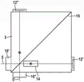
Fig. 4 shows an alternative exemplary embodiment of a reference interferometer 1 according to the present invention in plan view. It differs from the exemplary embodiment according to fig. 3 in that the beam splitter body is not provided as a cuboid but as an L-shaped structure with two separately formed interferometer arms.
Fig. 5 and 6 show respectively a cross section through an interferometer 8 according to the invention, the cross section in fig. 5 being realized along the interferometer arm without retarder layer (vertical arm in fig. 4, section AA). In contrast, fig. 6 shows a section through the interferometer arm with retarder coating 14 (horizontal arm in fig. 4, section BB).
In FIG. 5, the upper open circle 17 marks the location where the reference beam enters the beam splitter layer 19 to complete its path on both sides of the interferometer arm and the mirror element (12'). The solid line shows the optical axis of the reference beam; the dotted line shows the optical axis of the used light beam. The reference beam 5 enters the beam splitter body via an inclined entrance face of a prism 16' (not shown). After reflection at the beam splitter layer 19 (not shown), total internal reflection at the upper side 61, reflection at the mirror 12 ", total internal reflection at the lower side 62 of the beam splitter body, and transmission through the beam splitter layer 19 (not shown), the beam again exits the interferometer through the prism face 16". After leaving the interferometer, the reference beam 5 'extends parallel to the reflected use beam 10'.
Fig. 6 shows the optical path of a portion of the reference beam transmitted through the beam splitter layer 19 (not shown). The reference beam 5 enters the beam splitter body from the left via the inclined surface 16' in order to complete its path on both sides 61, 62 of the interferometer arm 2' and the mirror element 12 '. The optical axis of the reference beam is shown by a solid line. The use of a light beam is not shown in this figure. After total internal reflection at the retarder layer 14, reflection at the mirror 12' and total internal reflection at the underside 62, the beam leaves the beam body again through the beam splitter layer 19 (not shown). The lower open circle 18 in fig. 6 marks the location where the reference beam is diverted away from the beam splitter layer and away from the beam splitter. After refraction by the prism 16 "(not shown), the reference beam 5' extends parallel to the reflected use beam (not shown). A small portion of the reference beam reflected by mirror 12' is transmitted through beam splitter layer 19. This transmitted component either leaves the interferometer in the direction of the reference light source or is absorbed by the opaque coating 22 as shown.
Fig. 7 shows an example of the phase shift of the vertically and parallel (s-and p-) polarized light of the reference beam emerging from total internal reflection at the retarder layer 14. In the example shown, a laser beam 5 having a wavelength λ 638nm impinges on the entrance face of the prism 16', the normal to the entrance face of the reference beam 5 being inclined at an angle δ relative to the optical axis of the reference beam 5. The light beam is incident on the interface between the fused silica and the hafnium oxide layer 14 of the beam splitter 3 at an angle of incidence a of about 76.5 with respect to the normal. The magnitude of the phase shift can be controlled by a single layer of material having a suitable refractive index. When the laser beam is in fused silica (having a refractive index of, for example, n) of the beam splitter 311.46) and a hafnium oxide layer 14 (having a refractive index of, for example, n21.82) undergoes total internal reflection at the interface between them, a phase shift occurs. The angle beta with respect to the surface normal of the hafnium oxide layer 14 is about 49.7 deg.. It is evident from this figure that the hafnium oxide layer 14 takes on the function of the λ/4 plate 11 according to the conventional reference interferometer shown in fig. 1. Various effects contribute to the phase shift. The light beam 5 interferes with the component reflected at the interface between the beam splitter 3 and the hafnium oxide layer 14 and with the component reflected multiple times in the hafnium oxide layer 14, thus accumulating a larger phase shift. In general, this results in a modulation that is periodic with the thickness of the hafnium oxide layer 14. The reference beam, which is totally internally reflected, exits the beam splitter body at an angle epsilon and intersects the optical axis of the use beam at a mirror surface (12').
FIG. 8 shows a schematic diagram of the phase shift of the perpendicular and parallel (s-and p-) polarized reference beams as a function of the layer thickness of the retarder layer 14 as a result of total internal reflection.
Fig. 9 shows the phase difference of the s-polarized light and the p-polarized light of the reference beam as a function of the thickness of the retarder layer 14 in case of total internal reflection at the interface as shown in fig. 7. It is clear that a phase shift of pi/2 (corresponding to lambda/4) is achieved with a hafnium oxide layer having a thickness of 60nm or 120 nm. By adjusting the layer thicknesses and/or layer materials, virtually any desired phase shift can be achieved for any substrate material and angle of incidence.
The data shown in fig. 10 are simulated data, which were manually verified in a semi-analytical manner. The thickness of the hafnium oxide layer used for the measurement was about 58nm, about 93nm, about 121nm and about 149 nm. The phase shift between s-polarized light and p-polarized light was measured using a test interferometer. Fig. 10 shows a comparison of the theoretical values with the experimental values according to fig. 9. It is evident that the experimental and theoretical values agree well.
In principle, the exact value of the phase shift depends sensitively on the thickness of the coating and the angle of incidence of the light. In the case of applying the reference interferometer 1 to quadrature detection, an accurate phase shift of λ/4 is not essential; the deviation of lambda/20 is perfectly acceptable and therefore production-related tolerances should not represent any difficulties.
Claims (31)
1. Reference interferometer (1) for determining optical path length variations in an interferometer arm (2), comprising a beam splitter (3) and a laser light source (4), the beam splitter (3) being embodied such that a beam (5) of the laser light source (4) is guided by total internal reflection on a first side and a second side of the beam splitter (3),
characterized in that at least one prism (16') is arranged upstream of the beam splitter (3) in the beam path, wherein the upstream prism (16') is embodied such that a light beam which is directed substantially along or parallel to a central z-axis to the beam splitter can be refracted and directed obliquely to a first side of the beam splitter; and/or
Characterized in that at least one prism (16 ") is arranged in the beam path downstream of the beam splitter (3), wherein the downstream prism (16") is embodied such that a light beam exiting the beam splitter obliquely with respect to a central x axis can be refracted and guided substantially along the central x axis or a course parallel to the central x axis.
2. The reference interferometer (1) according to claim 1, wherein the optical path length variation is a relative optical path length variation.
3. The reference interferometer (1) according to claim 1, wherein said at least one prism (16') is a right triangular prism able to divert said light beam towards a first side of said beam splitter.
4. The reference interferometer (1) according to claim 1, wherein said at least one prism (16 ") is a right triangular prism able to refract a light beam incident from the second side of the beam splitter.
5. The reference interferometer (1) according to claim 1, characterized in that at least the first side and/or the second side of the beam splitter (3) is provided with a coating.
6. The reference interferometer (1) according to claim 5, characterized in that at least the first side and/or the second side of the beam splitter (3) is provided with a coating on a part thereof.
7. The reference interferometer (1) according to any one of claims 1 to 6, characterized in that the first side of the beam splitter (3) is an upper side (61) of the beam splitter (3) and the second side of the beam splitter (3) is a lower side (62) of the beam splitter (3).
8. The reference interferometer (1) according to any of claims 3 to 4, characterized in that the reference interferometer (1) is a Michelson-type reference interferometer.
9. The reference interferometer (1) according to any one of claims 5 to 6, characterized in that the refractive index and the thickness of the coating are chosen such that a phase shift of π/2 ± π/10 can be obtained between an s-polarized light beam and a p-polarized light beam undergoing total internal reflection in case the light beam (5) of the laser light source (4) has been reflected by total internal reflection.
10. The reference interferometer (1) according to any one of claims 5 to 6, characterized in that the refractive index and the thickness of the coating are chosen such that a phase shift of π/2 ± π/20 can be obtained between an s-polarized light beam and a p-polarized light beam undergoing total internal reflection in case the light beam (5) of the laser light source (4) has been reflected by total internal reflection.
11. The reference interferometer (1) according to any one of claims 1 to 6, characterized in that the beam splitter (3) is embodied as a parallelepiped.
12. The reference interferometer (1) as claimed in any of claims 1 to 6, characterized in that the beam splitter (3) is embodied as a right-angle rectangular prism.
13. The reference interferometer (1) according to any one of claims 1 to 6, characterized in that the beam splitter (3) is embodied as a cuboid.
14. The reference interferometer (1) according to any one of claims 1 to 6, characterized in that at least one detector (7) is provided.
15. The reference interferometer (1) as claimed in any of claims 1 to 6, characterized in that two photodetectors (7', 7 ") are provided for detecting the two partial beams which have been separated by the polarizing beam splitter (13).
16. The reference interferometer (1) as claimed in any of claims 1 to 6, characterized in that the laser light source (4) is a diode laser.
17. The reference interferometer (1) according to any one of claims 1 to 6, characterized in that the laser light source (4) is a distributed feedback laser, a distributed Bragg reflection laser or a vertical cavity surface emitting laser.
18. Use of a reference interferometer (1) according to any of claims 1 to 17 for monitoring optical path length variations in an interferometer arm (2).
19. Interferometer (8) comprising a reference interferometer (1) according to any of claims 1 to 17 for monitoring optical path length variations in an interferometer arm (2) and comprising a second light source (9) for an effective light beam (10) and a plurality of optical elements, wherein the effective light beam (10) of the light source (9) and the light beam (5) of a laser light source (4) can be directed through the same beam splitter (3) when used as intended, wherein the light beam (5) of the laser light source (4) represents the reference beam,
characterized in that at least one prism (16') is arranged in the light path upstream of the beam splitter (3) in order to be able to deflect a reference beam (5) which is directed substantially parallel to the effective beam (10) to the beam splitter (3) by means of the at least one prism; and/or
At least one prism (16') is arranged in the optical path downstream of the beam splitter (3) so that the reference beam (5') can be refracted by the at least one prism such that the effective beam (10') and the reference beam (5') leave the interferometer substantially parallel.
20. Interferometer according to claim 19, characterised in that the interferometer (8) is implemented as a two-beam interferometer.
21. Interferometer according to any of claims 19 to 20, characterised in that the reference interferometer (1) is implemented for quadrature detection.
22. The interferometer according to any one of claims 19 to 20, wherein the incidence position of the reference beam into a prism arranged upstream of the beam splitter and/or the incidence position of the effective beam into the beam splitter is provided with an anti-reflection coating.
23. The interferometer of claim 22, wherein an anti-reflection coating at the location of incidence where the reference beam enters a prism disposed upstream of the beam splitter matches the wavelength of the reference beam and an anti-reflection coating at the location of incidence where the effective beam enters the beam splitter matches the wavelength range of the effective beam.
24. A spectrometer comprising an interferometer (8) according to any of claims 19 to 23.
25. The spectrometer of claim 24, wherein the spectrometer is a near infrared spectrometer.
26. A method for determining optical path length variations in an interferometer arm (2), wherein a light beam (5) is radiated from a laser light source (4) onto a beam splitter (3) as a reference beam and is guided by total internal reflection on a first side of the beam splitter (3) and on a second side of the beam splitter (3), characterized in that the light beam is guided by at least one first prism (16') before entering the beam splitter and/or by at least one second prism (16 ") after exiting from the beam splitter, wherein the reference beam (5)
-propagating along or parallel to a central z-axis in a first part of the optical path before entering the first prism (16');
-propagating obliquely with respect to the central z-axis in the middle part of the optical path; and/or
-propagating along or parallel to a central x-axis in a third portion of said optical path after exiting from said second prism (16 ").
27. The method of claim 26 wherein the optical path length change is a relative optical path length change.
28. The method according to any one of claims 26 to 27, wherein the first side of the beam splitter (3) is an upper side (61) of the beam splitter (3) and the second side of the beam splitter (3) is a lower side (62) of the beam splitter (3).
29. The method according to any one of claims 26 to 27, wherein the polarization of the reference beam (5) is changed.
30. The method according to any one of claims 26 to 27, characterized in that the effective light beam (10) is directed on the same beam splitter (3) parallel to the reference beam (5) and is diverted by means of mirror elements (12',12 "), and the effective light beam (10') emerges from the beam splitter parallel to the reference beam (5 ').
31. Method according to claim 30, characterized in that the reference beam (5) and/or the effective beam (10) is captured by at least one detector (7).
Applications Claiming Priority (3)
| Application Number | Priority Date | Filing Date | Title |
|---|---|---|---|
| EP18158804.7 | 2018-02-27 | ||
| EP18158804.7A EP3531064A1 (en) | 2018-02-27 | 2018-02-27 | Beam guiding in interferometer |
| PCT/EP2019/054762 WO2019166446A1 (en) | 2018-02-27 | 2019-02-26 | Beam guidance in the interferometer |
Publications (2)
| Publication Number | Publication Date |
|---|---|
| CN111742190A CN111742190A (en) | 2020-10-02 |
| CN111742190B true CN111742190B (en) | 2022-07-12 |
Family
ID=61386775
Family Applications (1)
| Application Number | Title | Priority Date | Filing Date |
|---|---|---|---|
| CN201980014749.2A Active CN111742190B (en) | 2018-02-27 | 2019-02-26 | Beam guiding in an interferometer |
Country Status (4)
| Country | Link |
|---|---|
| EP (2) | EP3531064A1 (en) |
| CN (1) | CN111742190B (en) |
| ES (1) | ES2946634T3 (en) |
| WO (1) | WO2019166446A1 (en) |
Families Citing this family (3)
| Publication number | Priority date | Publication date | Assignee | Title |
|---|---|---|---|---|
| CN212623373U (en) * | 2020-06-01 | 2021-02-26 | 三赢科技(深圳)有限公司 | Optical module and dot matrix projection equipment |
| CN113311588B (en) * | 2021-05-31 | 2022-03-18 | 北京理工大学 | Orbital angular momentum beam splitter |
| CN114739286B (en) * | 2022-04-25 | 2023-07-04 | 中国科学院合肥物质科学研究院 | Dual-wavelength composite laser interferometer system |
Citations (6)
| Publication number | Priority date | Publication date | Assignee | Title |
|---|---|---|---|---|
| JP2001249048A (en) * | 2000-03-06 | 2001-09-14 | Nippon Telegr & Teleph Corp <Ntt> | Michelson interferometer |
| CN101430391A (en) * | 2008-12-18 | 2009-05-13 | 山东师范大学 | Large-misplacement square glass prism for implementing electronic speckle interference |
| CN101650166A (en) * | 2008-08-15 | 2010-02-17 | 上海理工大学 | Laser interference system used for measuring micro roll angle |
| JP2011064674A (en) * | 2009-08-21 | 2011-03-31 | Canon Inc | Laser gauge interferometer, machining device using the same, and machining method of work piece |
| CN102782465A (en) * | 2010-01-18 | 2012-11-14 | 科学技术设备委员会 | Compact interferometer spectrometer |
| CN103635775A (en) * | 2011-06-27 | 2014-03-12 | 赫克斯冈技术中心 | Interferometric distance measuring method for measuring surfaces, and such a measuring arrangement |
Family Cites Families (3)
| Publication number | Priority date | Publication date | Assignee | Title |
|---|---|---|---|---|
| DE3404963C2 (en) * | 1984-02-11 | 1986-09-25 | Fraunhofer-Gesellschaft zur Förderung der angewandten Forschung e.V., 8000 München | Laser interferometer for length measurement |
| JP2007316486A (en) * | 2006-05-29 | 2007-12-06 | Olympus Corp | Variable spectral element, spectroscope and endoscope system |
| CN102252764B (en) * | 2010-05-17 | 2012-12-05 | 中国计量科学研究院 | Laser wavelength real-time measurement device |
-
2018
- 2018-02-27 EP EP18158804.7A patent/EP3531064A1/en not_active Withdrawn
-
2019
- 2019-02-26 CN CN201980014749.2A patent/CN111742190B/en active Active
- 2019-02-26 WO PCT/EP2019/054762 patent/WO2019166446A1/en unknown
- 2019-02-26 ES ES19708983T patent/ES2946634T3/en active Active
- 2019-02-26 EP EP19708983.2A patent/EP3759421B1/en active Active
Patent Citations (6)
| Publication number | Priority date | Publication date | Assignee | Title |
|---|---|---|---|---|
| JP2001249048A (en) * | 2000-03-06 | 2001-09-14 | Nippon Telegr & Teleph Corp <Ntt> | Michelson interferometer |
| CN101650166A (en) * | 2008-08-15 | 2010-02-17 | 上海理工大学 | Laser interference system used for measuring micro roll angle |
| CN101430391A (en) * | 2008-12-18 | 2009-05-13 | 山东师范大学 | Large-misplacement square glass prism for implementing electronic speckle interference |
| JP2011064674A (en) * | 2009-08-21 | 2011-03-31 | Canon Inc | Laser gauge interferometer, machining device using the same, and machining method of work piece |
| CN102782465A (en) * | 2010-01-18 | 2012-11-14 | 科学技术设备委员会 | Compact interferometer spectrometer |
| CN103635775A (en) * | 2011-06-27 | 2014-03-12 | 赫克斯冈技术中心 | Interferometric distance measuring method for measuring surfaces, and such a measuring arrangement |
Also Published As
| Publication number | Publication date |
|---|---|
| EP3531064A1 (en) | 2019-08-28 |
| WO2019166446A1 (en) | 2019-09-06 |
| CN111742190A (en) | 2020-10-02 |
| EP3759421A1 (en) | 2021-01-06 |
| EP3759421B1 (en) | 2023-03-15 |
| ES2946634T3 (en) | 2023-07-21 |
Similar Documents
| Publication | Publication Date | Title |
|---|---|---|
| US7826064B2 (en) | Interferometer system for monitoring an object | |
| CN111742190B (en) | Beam guiding in an interferometer | |
| JP5226078B2 (en) | Interferometer device and method of operating the same | |
| US7864336B2 (en) | Compact Littrow encoder | |
| JP4316691B2 (en) | Device for measuring excursion | |
| US7710581B2 (en) | Wavelength monitoring method and apparatus and method of making same | |
| US10024647B2 (en) | Method of air refractive index correction for absolute long distance measurement | |
| US9810521B2 (en) | Displacement detection apparatus | |
| JP6063166B2 (en) | Mechanism for measuring the distance by interferometer method | |
| US9518816B2 (en) | Dual beam splitter interferometer measuring 3 degrees of freedom, system and method of use | |
| JP2007537436A (en) | Polarization interferometer with error beam removal or separation caused by polarization leakage | |
| JPH0329802A (en) | Interferometer | |
| CN111373301B (en) | Method and device for contactless measurement of the distance to a surface or the distance between two surfaces | |
| JP4208069B2 (en) | Refractive index and thickness measuring apparatus and measuring method | |
| JPH03504768A (en) | Interferometer system for measuring distance and shift movements, especially of moving components | |
| JP2006500570A (en) | Interference measurement device | |
| CN110785623B (en) | Distance measuring device for determining a distance to an object | |
| US20030035112A1 (en) | Birefringent beam combiners for polarized beams in interferometers | |
| JP4461018B2 (en) | Frequency stabilized laser system including pulse modulation of backscattered light | |
| KR102130576B1 (en) | Thickness And Refractive Index Measuring Apparatus Without Non-measuring Ranges | |
| KR100422378B1 (en) | Fizeau interferometer using angled end-face optical fiber source | |
| JP2003329422A (en) | Shape measuring instrument | |
| KR20060031199A (en) | Fizeau interferometer for refraction index measurement | |
| JP2003035513A (en) | Laser measuring machine | |
| JPH05126519A (en) | Semiconductor laser length-measuring device |
Legal Events
| Date | Code | Title | Description |
|---|---|---|---|
| PB01 | Publication | ||
| PB01 | Publication | ||
| SE01 | Entry into force of request for substantive examination | ||
| SE01 | Entry into force of request for substantive examination | ||
| GR01 | Patent grant | ||
| GR01 | Patent grant |