CN111733839A - Method for reinforcing receiving end of deep-buried shield water-rich sand layer next to excavation foundation pit - Google Patents
Method for reinforcing receiving end of deep-buried shield water-rich sand layer next to excavation foundation pit Download PDFInfo
- Publication number
- CN111733839A CN111733839A CN202010547520.XA CN202010547520A CN111733839A CN 111733839 A CN111733839 A CN 111733839A CN 202010547520 A CN202010547520 A CN 202010547520A CN 111733839 A CN111733839 A CN 111733839A
- Authority
- CN
- China
- Prior art keywords
- construction
- reinforcing
- pile
- internal
- mjs
- Prior art date
- Legal status (The legal status is an assumption and is not a legal conclusion. Google has not performed a legal analysis and makes no representation as to the accuracy of the status listed.)
- Pending
Links
Images


Classifications
-
- E—FIXED CONSTRUCTIONS
- E02—HYDRAULIC ENGINEERING; FOUNDATIONS; SOIL SHIFTING
- E02D—FOUNDATIONS; EXCAVATIONS; EMBANKMENTS; UNDERGROUND OR UNDERWATER STRUCTURES
- E02D19/00—Keeping dry foundation sites or other areas in the ground
-
- E—FIXED CONSTRUCTIONS
- E02—HYDRAULIC ENGINEERING; FOUNDATIONS; SOIL SHIFTING
- E02D—FOUNDATIONS; EXCAVATIONS; EMBANKMENTS; UNDERGROUND OR UNDERWATER STRUCTURES
- E02D19/00—Keeping dry foundation sites or other areas in the ground
- E02D19/06—Restraining of underground water
-
- E—FIXED CONSTRUCTIONS
- E02—HYDRAULIC ENGINEERING; FOUNDATIONS; SOIL SHIFTING
- E02D—FOUNDATIONS; EXCAVATIONS; EMBANKMENTS; UNDERGROUND OR UNDERWATER STRUCTURES
- E02D19/00—Keeping dry foundation sites or other areas in the ground
- E02D19/06—Restraining of underground water
- E02D19/10—Restraining of underground water by lowering level of ground water
-
- E—FIXED CONSTRUCTIONS
- E02—HYDRAULIC ENGINEERING; FOUNDATIONS; SOIL SHIFTING
- E02D—FOUNDATIONS; EXCAVATIONS; EMBANKMENTS; UNDERGROUND OR UNDERWATER STRUCTURES
- E02D5/00—Bulkheads, piles, or other structural elements specially adapted to foundation engineering
- E02D5/18—Bulkheads or similar walls made solely of concrete in situ
-
- E—FIXED CONSTRUCTIONS
- E02—HYDRAULIC ENGINEERING; FOUNDATIONS; SOIL SHIFTING
- E02D—FOUNDATIONS; EXCAVATIONS; EMBANKMENTS; UNDERGROUND OR UNDERWATER STRUCTURES
- E02D5/00—Bulkheads, piles, or other structural elements specially adapted to foundation engineering
- E02D5/22—Piles
- E02D5/34—Concrete or concrete-like piles cast in position ; Apparatus for making same
-
- E—FIXED CONSTRUCTIONS
- E21—EARTH DRILLING; MINING
- E21D—SHAFTS; TUNNELS; GALLERIES; LARGE UNDERGROUND CHAMBERS
- E21D9/00—Tunnels or galleries, with or without linings; Methods or apparatus for making thereof; Layout of tunnels or galleries
- E21D9/001—Improving soil or rock, e.g. by freezing; Injections
Abstract
The invention discloses a method for reinforcing a receiving end head of a deep-buried shield water-rich sand layer close to an excavated foundation pit, which comprises the following construction steps: step 1: designing an end reinforcement combination form and related parameters according to a traditional end reinforcement method and by combining the condition of a reinforcement area, and designing into an internal MJS construction method pile, an external U-shaped plain ground connecting wall and an internal and external dewatering well; step 2: carrying out internal reinforcement construction by adopting special equipment for the piles in the construction method according to the MJS pile position design; and step 3: adopting a trenching machine to carry out MJS reinforcement body peripheral plain ground wall connection construction; and 4, step 4: reinforcing construction is carried out on weak positions of the peripheral plain ground connecting wall by adopting special equipment for the construction method piles; and 5: and adopting a reverse circulation drill to carry out construction of the dewatering well inside and outside the plain ground connecting wall. The invention improves the reinforcement quality on the premise of ensuring synchronous and safe excavation of the near deep foundation pit, and has the advantages of higher construction efficiency, strong adaptability, civilization and environmental protection.
Description
Technical Field
The invention relates to the technical field of shield tunnel construction, in particular to a method for reinforcing a receiving end close to a deep-buried shield water-rich sand layer of an excavated foundation pit.
Background
With the rapid development of infrastructure construction in China, the shield construction method is widely applied to urban subway and sewage tunnel construction with safety and high efficiency. The shield receiving is one of the most main risk points in the shield construction process, and the key for controlling the risk is to select a proper shield receiving end reinforcing scheme.
The traditional end head reinforcing method such as the single or the mutual overlapping use of a high-pressure jet grouting pile, a CSM stirring wall, a plain ground connecting wall and a dewatering well has the limitations of the traditional end head reinforcing method, namely the safety of synchronous excavation of a foundation pit is difficult to ensure, and the expected reinforcing effect in a large-depth water-rich sand layer is difficult to achieve.
Disclosure of Invention
In order to overcome the technical defects that the traditional end reinforcing method in the prior art is difficult to ensure the safety of foundation pit synchronous excavation and achieve the expected reinforcing effect in a large-depth water-rich sand layer, the invention provides the method for reinforcing the receiving end of the deep-buried shield water-rich sand layer close to the excavated foundation pit, which can be adjusted timely according to the field and shaft conditions, is particularly suitable for end reinforcing construction under unfavorable geological conditions of an ultra-deep foundation pit, an ultra-thick sand layer, ultra-high confined water and the like, and solves the technical problems.
The invention achieves the aim through the following technical scheme, and a method for reinforcing a receiving end head of a deep-buried shield water-rich sand layer close to an excavated foundation pit comprises the following construction steps:
s1: designing an end head reinforcing combination form and related parameters:
designing an end head reinforcing combination form and related parameters according to a traditional reinforcing method and by combining the condition of a reinforcing area, wherein the reinforcing concept is designed by taking double-layer water plugging as a main part and taking internal and external precipitation as an auxiliary part, namely, adopting internal MJS construction method piles to perform inner layer water plugging, adopting a U-shaped plain ground connecting wall as an outer layer water plugging, arranging an internal dewatering and dewatering well in the middle position of the internal MJS construction method piles and the U-shaped plain ground connecting wall, and arranging an external precipitation well at the periphery of the U-shaped plain ground connecting wall;
s2: adopting construction method pile special equipment to carry out construction of the internal MJS construction pile reinforcing body:
adopting a hole leading machine and an MJS construction method host machine, and being provided with a cement tank, a high-pressure pump, a clean water pump and an excavator to reasonably carry out construction method pile construction according to the distribution condition of the internal MJS construction method pile, wherein the construction steps are mainly as follows: drilling a guide drill bit into a hole, placing a sleeve, drilling a pile drill bit from the sleeve to the bottom, pulling the sleeve back in sections, and spraying cement to the top of the pile;
s3: adopting a trenching machine to carry out the construction of the peripheral U-shaped plain ground connecting wall:
adopting a trenching machine to be provided with a slurry system, a fore shaft pipe and a guide pipe to carry out amplitude jump construction according to the amplitude division condition of the plain wall;
s4: and (3) reinforcing construction of the plain wall joint MJS-method piles is performed on the periphery of the weak part of the U-shaped plain ground diaphragm wall:
local reinforcement processing is carried out on the MJS construction method piles at the joint of the plain wall outside the joint position of the U-shaped plain ground diaphragm wall, and the construction steps are consistent with those of the internal MJS construction method piles;
s5: adopting a reverse circulation drill to carry out the construction of the U-shaped plain ground connection wall internal and external dewatering well:
and (4) adopting a reverse circulation drill with rock entering capability to carry out the construction of the dewatering well in the reinforced area according to the geological condition.
According to the method for reinforcing the receiving end of the deep-buried shield water-rich sand layer next to the excavated foundation pit, the pile forming and reinforcing principle of the internal MJS construction method pile is greatly different from the traditional reinforcing method such as a high-pressure jet grouting pile and a CSM stirring wall, the high-pressure jet grouting pile and the CSM stirring wall are mixed and reinforced by injecting cement slurry into a stirring soil body, and the MJS construction method pile firstly leads a hole to the bottom of the pile, then a sleeve is put, and a construction method pile drill bit is drilled from the sleeve to the bottom and then lifted up section by section and sprayed with high-pressure cement slurry to cut the surrounding soil body; the underground pressure is controlled by adjusting the forced mud discharge amount, so that deep mud discharge and the underground pressure are reasonably controlled, the possibility of surface deformation in construction is reduced, and the influence on the environment is greatly reduced.
According to the method for reinforcing the receiving end of the deep-buried shield water-rich sand layer next to the excavated foundation pit, the seam of the U-shaped plain diaphragm wall is processed by the aid of the locking pipe, and the wall of the U-shaped plain diaphragm wall is closely attached to the wall of the trench wall, so that concrete is prevented from flowing backwards and flowing around.
According to the method for reinforcing the receiving end of the deep-buried shield water-rich sand layer adjacent to the excavation foundation pit, secondary reinforcing treatment is performed on the weak joint of the U-shaped plain ground diaphragm wall, the water retaining capacity of the plain wall outside the reinforcing area is improved, and the reinforcing effect of the peripheral reinforcing body is enhanced.
According to the method for reinforcing the receiving end of the deep-buried shield water-rich sand layer next to the excavated foundation pit, the dewatering wells are distributed on the inner side and the outer side of the U-shaped plain ground diaphragm wall, and when confined water enters the U-shaped plain ground diaphragm wall from a joint, the external dewatering wells pump and drain water, so that the local water head elevation at the joint is reduced, and the amount of groundwater entering the U-shaped plain ground diaphragm wall is reduced; an internal dewatering and dewatering well is arranged between the U-shaped plain ground diaphragm wall and the MJS reinforcing body, so that underground water entering the U-shaped plain ground diaphragm wall can be collected and pumped out in time, and the overall quality of a reinforcing area is improved.
According to the method for reinforcing the receiving end head of the deep-buried shield water-rich sand layer next to the excavated foundation pit, the designed pile diameter value of the internal MJS construction method pile is 1.2m, the elevation of the bottom of the internal MJS construction method pile and the U-shaped plain earth connecting wall is more than 3.0m lower than that of the bottom of the shield tunnel, and the elevation of the bottom of the precipitation shaft is flush with that of the bottom of the shield tunnel.
Generally, compared with the prior art, the technical scheme of the invention can achieve the following beneficial effects:
1. the end reinforcing method disclosed by the invention combines the MJS process with the receiving and reinforcing of the tunnel end for the first time, further optimizes the combination form of the traditional high-pressure jet grouting pile, the plain ground connecting wall and the precipitation well, innovatively provides the end reinforcing method combining the MJS construction pile, the U-shaped plain ground connecting wall and the internal and external precipitation well, abandons the traditional single water-stopping reinforcing concept, and forms the reinforcing concept mainly based on double-layer water plugging and assisting the internal and external precipitation;
2. the combined reinforcement construction method of the MJS + plain wall + dewatering well can get rid of the limitation of the traditional reinforcement method, can be adjusted timely according to the field and shaft conditions, and is particularly suitable for end reinforcement construction under unfavorable geological conditions such as ultra-deep foundation pits, ultra-thick sand layers, ultra-high confined water and the like.
3. The end reinforcement method provided by the invention is a reinforcement method which is based on double-layer water plugging and assisted by water dropping and is further deepened on the basis of simple traditional reinforcement method based on water dropping and assisted by water dropping, double water insulation of a peripheral plain wall and an MJS reinforcement body is realized, and the effect of good environment receiving is achieved by matching with water dropping of an internal precipitation well and an external precipitation well, and the diameter and the quality of a pile formed in a deep layer of the new process MJS construction method pile are superior to those of a high-pressure jet grouting pile by adjusting the underground pressure.
4. The end reinforcement method is safe, green and environment-friendly, the underground pressure can be controlled by adjusting the forced slurry discharge amount of the MJS construction method pile in the construction method, the slurry overflow and the ground surface deformation are effectively controlled, when the vertical shaft is synchronously excavated, the inner MJS construction method pile is firstly constructed to stabilize the end stratum, and then the outer U-shaped plain wall is constructed, so that the synchronous excavation safety of the foundation pit is ensured.
Drawings
The following detailed description of embodiments of the invention is provided in conjunction with the appended drawings, in which:
FIG. 1 is a construction flow chart of a method for reinforcing a receiving end head of a deep-buried shield water-rich sand layer close to an excavated foundation pit according to the invention;
FIG. 2 is a schematic plan view of a reinforcement for an end of an embodiment of the present invention;
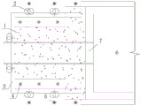
FIG. 3 is a schematic cross-sectional view of an embodiment of an end reinforcement of the present invention;
FIG. 4 is a schematic view of the water stopping effect of the head reinforcement in the embodiment of the present invention;
in the figure: 1-internal MJS construction method pile, 2-plain wall joint MJS construction method pile, 3-U-shaped plain ground connecting wall, 4-internal drainage dewatering well, 5-external dewatering well, 6-9# vertical shaft and 7-shield tunnel.
Detailed Description
As shown in fig. 1, a construction flow chart of a method for reinforcing a receiving end of a deep-buried shield water-rich sand layer next to an excavated foundation pit according to the present invention is shown, wherein the method for reinforcing the receiving end comprises the following construction steps:
the method comprises the following steps: designing an end head reinforcing combination form and related parameters:
according to the traditional reinforcement method, an end reinforcement combination form and related parameters are designed by combining the condition of a reinforcement area, the design reinforcement concept is that double-layer water plugging is mainly adopted, inner and outer precipitation is used as assistance, namely, an A1200@1000mm inner MJS construction method pile 1 is adopted for inner layer water plugging, an 800mmU type plain ground diaphragm wall 3 is adopted for outer layer water plugging, an inner dewatering and dewatering well 4 is arranged in the middle position of the inner MJS construction method pile 1 and the U type plain ground diaphragm wall 3, and an outer dewatering well 5 is arranged on the periphery of the U type plain ground diaphragm wall 3, as shown in figures 2 and 3, the plane schematic diagram and the section schematic diagram of end reinforcement are shown.
Step two: and (3) adopting construction method pile special equipment to construct the reinforcing body of the inner MJS construction method pile 1:
adopting a hole leading machine and an MJS construction method host machine, and being provided with a cement tank, a high-pressure pump, a clean water pump and an excavator to reasonably carry out construction method pile construction according to the distribution condition of the internal MJS construction method piles 1, wherein the construction steps are mainly as follows: pilot bit drilling down to form hole → casing setting → construction pile bit drilling down from casing to bottom → casing segment pulling back and spraying to pile top.
Step three: and (3) constructing the peripheral U-shaped plain ground connecting wall 3 by adopting a trenching machine:
adopting the grooving machine to be equipped with a slurry system, a fore shaft pipe and a guide pipe to carry out amplitude jump construction according to the framing condition of the plain wall, wherein the construction steps are mainly as follows: manufacturing a guide wall → configuring slurry → grooving by a grooving machine → hanging and placing a locking pipe → pouring concrete → jacking and pulling the locking pipe.
Step four: and (3) reinforcing construction of the plain wall joint MJS construction pile 2 is carried out on the periphery of the weak part of the U-shaped plain ground diaphragm wall 3:
local reinforcement processing is carried out on the plain wall joint MJS construction method piles 2 outside the joint positions of the U-shaped plain ground connecting walls 3, particularly the construction steps of the U-shaped plain ground connecting walls 3 and 9# vertical shaft 6 crown beams are consistent with those of the internal MJS construction method piles 1.
Step five: adopting a reverse circulation drill to carry out the construction of the internal and external dewatering wells of the U-shaped plain ground connecting wall 3:
adopting the reverse circulation drill that possesses into rock ability to consolidate regional precipitation well construction according to the geological conditions, the construction step mainly is: drilling to form a hole → filling a filter material in a lower well pipe → sealing a water-stop hole and washing a well → pumping water by a lower pump.
The end reinforcement method provided by the invention is a reinforcement method which is based on double-layer water plugging and assisted by water dropping and is based on simple traditional reinforcement method and assisted by water dropping, the double water-resisting of the peripheral U-shaped plain ground connecting wall 3 and the MJS reinforcement body is matched with the internal and external precipitation wells to achieve the effect of good environment receiving, the diameter and quality of the pile formed in the deep layer of the new process MJS construction method pile are superior to those of a high-pressure jet grouting pile by adjusting the underground pressure, as shown in figure 4, the end reinforcement water-stop effect is a schematic diagram.
The MJS construction method pile can control the underground pressure by adjusting the forced slurry discharge amount, thereby effectively controlling the slurry overflow and the surface deformation, when the 9# vertical shaft 6 is synchronously excavated, firstly constructing the inner MJS construction method pile 1 to stabilize the end stratum, and then constructing the outer U-shaped plain ground connecting wall 3, thereby ensuring the synchronous excavation safety of the foundation pit.
It will be understood by those skilled in the art that the foregoing is only a preferred embodiment of the present invention, and is not intended to limit the invention, and that any modification, equivalent replacement, or improvement made within the spirit and principle of the present invention should be included in the scope of the present invention.
Claims (4)
1. A method for reinforcing a receiving end head of a deep-buried shield water-rich sand layer next to an excavated foundation pit is characterized by comprising the following construction steps:
s1: designing an end head reinforcing combination form and related parameters:
designing an end reinforcement combination form and related parameters according to a traditional reinforcement method and by combining the condition of a reinforcement area, wherein the design reinforcement concept is that double-layer water plugging is mainly adopted, internal and external precipitation is assisted, namely, an internal MJS construction method pile (1) is adopted for carrying out inner-layer water plugging, a U-shaped plain ground connecting wall (3) is adopted for outer-layer water plugging, an internal dewatering and dewatering well (4) is arranged in the middle position of the internal MJS construction method pile (1) and the U-shaped plain ground connecting wall (3), and an external precipitation well (5) is arranged on the periphery of the U-shaped plain ground connecting wall (3);
s2: the construction of reinforcing bodies of the internal MJS construction method pile (1) is carried out by adopting construction method pile special equipment:
adopting a hole leading machine and an MJS construction method host machine, and being provided with a cement tank, a high-pressure pump, a clean water pump and an excavator to reasonably carry out construction of the construction method piles according to the distribution condition of the internal MJS construction method piles (1), wherein the construction steps are mainly as follows: drilling a guide drill bit into a hole, placing a sleeve, drilling a pile drill bit from the sleeve to the bottom, pulling the sleeve back in sections, and spraying cement to the top of the pile;
s3: and (3) constructing the peripheral U-shaped plain ground connecting wall (3) by adopting a trenching machine:
adopting a trenching machine to be provided with a slurry system, a fore shaft pipe and a guide pipe to carry out amplitude jump construction according to the amplitude division condition of the plain wall;
s4: and (3) reinforcing construction of the plain wall joint MJS construction pile (2) is carried out on the periphery of the weak part of the U-shaped plain ground connecting wall (3):
local reinforcement processing is carried out on the plain wall joint MJS construction method pile (2) outside the joint position of the U-shaped plain ground connecting wall (3), and the construction steps are consistent with those of the inner MJS construction method pile (1);
s5: the construction of the inner and outer dewatering wells of the U-shaped plain ground connecting wall (3) is carried out by adopting a reverse circulation drill:
and (4) adopting a reverse circulation drill with rock entering capability to carry out the construction of the dewatering well in the reinforced area according to the geological condition.
2. The method for reinforcing the receiving end of the deep-buried shield water-rich sand layer next to the excavated foundation pit according to claim 1, wherein in the step S1, the designed pile diameter of the internal MJS construction method pile (1) is 1.2m, the elevation of the bottom of the internal MJS construction method pile (1) and the U-shaped plain ground connecting wall (3) is more than 3.0m lower than the elevation of the bottom of the shield tunnel (7), and the elevation of the bottom of the internal drainage precipitation well (4) and the external precipitation well (5) is flush with the elevation of the bottom of the shield tunnel (7).
3. The method for reinforcing the receiving end of the deep-buried shield water-rich sand layer next to the excavated foundation pit according to claim 1, wherein the U-shaped plain underground diaphragm wall (3) in the step S3 is constructed, the framing position is subjected to seam treatment by using a locking notch pipe, and the pipe wall is closely attached to the groove wall.
4. The method for reinforcing the receiving end of the deep-buried shield water-rich sand layer next to the excavated foundation pit according to claim 1, wherein in the dewatering well construction in the step S5, when confined water enters the U-shaped plain ground diaphragm wall (3) from the joint, the external dewatering well (5) pumps and drains water to reduce the elevation of the local water head at the joint and reduce the amount of groundwater entering the U-shaped plain ground diaphragm wall (3); an internal dewatering and dewatering well (4) is arranged between the U-shaped plain ground diaphragm wall (3) and the reinforcing body of the internal MJS construction method pile (1), and underground water entering the U-shaped plain ground diaphragm wall (3) is collected and pumped out in time, so that the overall quality of a reinforcing area is improved.
Priority Applications (1)
| Application Number | Priority Date | Filing Date | Title |
|---|---|---|---|
| CN202010547520.XA CN111733839A (en) | 2020-06-16 | 2020-06-16 | Method for reinforcing receiving end of deep-buried shield water-rich sand layer next to excavation foundation pit |
Applications Claiming Priority (1)
| Application Number | Priority Date | Filing Date | Title |
|---|---|---|---|
| CN202010547520.XA CN111733839A (en) | 2020-06-16 | 2020-06-16 | Method for reinforcing receiving end of deep-buried shield water-rich sand layer next to excavation foundation pit |
Publications (1)
| Publication Number | Publication Date |
|---|---|
| CN111733839A true CN111733839A (en) | 2020-10-02 |
Family
ID=72649333
Family Applications (1)
| Application Number | Title | Priority Date | Filing Date |
|---|---|---|---|
| CN202010547520.XA Pending CN111733839A (en) | 2020-06-16 | 2020-06-16 | Method for reinforcing receiving end of deep-buried shield water-rich sand layer next to excavation foundation pit |
Country Status (1)
| Country | Link |
|---|---|
| CN (1) | CN111733839A (en) |
Cited By (2)
| Publication number | Priority date | Publication date | Assignee | Title |
|---|---|---|---|---|
| CN112813985A (en) * | 2021-01-04 | 2021-05-18 | 上海市机械施工集团有限公司 | Shallow gas protection method for foundation pit |
| CN115341554A (en) * | 2022-08-30 | 2022-11-15 | 中建八局第三建设有限公司 | Construction method for plugging and reinforcing and protecting underground diaphragm wall with defects under water-rich silt stratum |
Citations (5)
| Publication number | Priority date | Publication date | Assignee | Title |
|---|---|---|---|---|
| US4516878A (en) * | 1981-10-13 | 1985-05-14 | Linde Aktiengesellschaft | Tunnel constructing |
| CN106988753A (en) * | 2017-05-08 | 2017-07-28 | 中建三局基础设施工程有限公司 | A kind of U-shaped plain concrete ground-connecting-wall adds steel bushing shield structure and its method of reseptance |
| CN107091095A (en) * | 2017-06-19 | 2017-08-25 | 中建隧道建设有限公司 | Existing tunnel MJS engineering methods stake reinforcement system and construction method are worn under water-rich sand layer shield |
| CN108625863A (en) * | 2018-03-21 | 2018-10-09 | 浙江大学城市学院 | A kind of weak soil shield receives control and reinforcement means |
| CN108798686A (en) * | 2018-06-27 | 2018-11-13 | 中铁十二局集团有限公司 | Tunneling boring water-rich sand layer shield receives construction method |
-
2020
- 2020-06-16 CN CN202010547520.XA patent/CN111733839A/en active Pending
Patent Citations (5)
| Publication number | Priority date | Publication date | Assignee | Title |
|---|---|---|---|---|
| US4516878A (en) * | 1981-10-13 | 1985-05-14 | Linde Aktiengesellschaft | Tunnel constructing |
| CN106988753A (en) * | 2017-05-08 | 2017-07-28 | 中建三局基础设施工程有限公司 | A kind of U-shaped plain concrete ground-connecting-wall adds steel bushing shield structure and its method of reseptance |
| CN107091095A (en) * | 2017-06-19 | 2017-08-25 | 中建隧道建设有限公司 | Existing tunnel MJS engineering methods stake reinforcement system and construction method are worn under water-rich sand layer shield |
| CN108625863A (en) * | 2018-03-21 | 2018-10-09 | 浙江大学城市学院 | A kind of weak soil shield receives control and reinforcement means |
| CN108798686A (en) * | 2018-06-27 | 2018-11-13 | 中铁十二局集团有限公司 | Tunneling boring water-rich sand layer shield receives construction method |
Non-Patent Citations (2)
| Title |
|---|
| 沈中江: "MJS工法在地铁端头盾构洞口加固的应用", 《绿色科技》 * |
| 贲志江等: "地铁过江隧道大型泥水盾构的水中接收技术", 《南京林业大学学报(自然科学版)》 * |
Cited By (2)
| Publication number | Priority date | Publication date | Assignee | Title |
|---|---|---|---|---|
| CN112813985A (en) * | 2021-01-04 | 2021-05-18 | 上海市机械施工集团有限公司 | Shallow gas protection method for foundation pit |
| CN115341554A (en) * | 2022-08-30 | 2022-11-15 | 中建八局第三建设有限公司 | Construction method for plugging and reinforcing and protecting underground diaphragm wall with defects under water-rich silt stratum |
Similar Documents
| Publication | Publication Date | Title |
|---|---|---|
| CN101139838B (en) | Construction method for high artesian area ultra-deep foundation pit | |
| CN105863648B (en) | A kind of tunneling is shallow to cover large-section tunnel construction method | |
| CN203174616U (en) | Clay foundation rain falling and water saving system | |
| CN103726496A (en) | Circular deep foundation pit bored secant pile wall supporting construction method | |
| CN104404974A (en) | High-pressure-bearing water and thick sand and pebble formation deep foundation pit grouting bottom-sealing structure and construction technology thereof | |
| CN111733839A (en) | Method for reinforcing receiving end of deep-buried shield water-rich sand layer next to excavation foundation pit | |
| CN108867673A (en) | A kind of underwater prevention method in the foundation pit based on the curtain that draws water | |
| CN216342131U (en) | Shield tunnel invades limit stake and handles reinforced structure | |
| CN109853604A (en) | A kind of static pressure waterpower suction open caisson construction method | |
| CN212641468U (en) | Pit-in-pit rapid construction structure | |
| CN101251020A (en) | Subsection hole-drilling repeatedly slip-casting method | |
| CN111764396A (en) | Construction method for water-rich stratum pit-in-pit | |
| CN111411639A (en) | Shallow foundation pit dewatering construction method for water-rich pebble layer | |
| CN111042171A (en) | Open caisson construction method suitable for silt soft soil foundation and high underground water level | |
| CN105040705A (en) | Ground foundation treatment construction technology under multi-karst-cave geological conditions | |
| CN110144871A (en) | A kind of dark creek processing construction method | |
| CN203684233U (en) | Circular support structure for deep foundation pit | |
| CN105113513A (en) | Anti-seepage foundation pit supporting structure and construction method | |
| CN105586978A (en) | Construction method of soil replacement stir waterproof curtain based on gravels | |
| CN215367226U (en) | Well draw reaming body expanding pile of solid reinforcing of back slip casting root | |
| CN204435321U (en) | A kind of steam power station water intaking open channel | |
| CN110878557B (en) | Layered bidirectional drainage method for foundation pit dewatering | |
| CN114482099A (en) | Steel sheet pile cofferdam construction method | |
| CN113605380A (en) | Construction method of cast-in-situ bored pile | |
| CN113202123A (en) | Construction method for treating high-span section strong karst filling and curtain seepage-proofing method |
Legal Events
| Date | Code | Title | Description |
|---|---|---|---|
| PB01 | Publication | ||
| PB01 | Publication | ||
| SE01 | Entry into force of request for substantive examination | ||
| SE01 | Entry into force of request for substantive examination | ||
| RJ01 | Rejection of invention patent application after publication | ||
| RJ01 | Rejection of invention patent application after publication |
Application publication date: 20201002 |