CN111715558A - Automatic detection and screening system with multiple conveying discs - Google Patents
Automatic detection and screening system with multiple conveying discs Download PDFInfo
- Publication number
- CN111715558A CN111715558A CN202010415398.0A CN202010415398A CN111715558A CN 111715558 A CN111715558 A CN 111715558A CN 202010415398 A CN202010415398 A CN 202010415398A CN 111715558 A CN111715558 A CN 111715558A
- Authority
- CN
- China
- Prior art keywords
- detection
- disc body
- rotary disc
- feeding
- screening system
- Prior art date
- Legal status (The legal status is an assumption and is not a legal conclusion. Google has not performed a legal analysis and makes no representation as to the accuracy of the status listed.)
- Granted
Links
Images


Classifications
-
- B—PERFORMING OPERATIONS; TRANSPORTING
- B07—SEPARATING SOLIDS FROM SOLIDS; SORTING
- B07C—POSTAL SORTING; SORTING INDIVIDUAL ARTICLES, OR BULK MATERIAL FIT TO BE SORTED PIECE-MEAL, e.g. BY PICKING
- B07C5/00—Sorting according to a characteristic or feature of the articles or material being sorted, e.g. by control effected by devices which detect or measure such characteristic or feature; Sorting by manually actuated devices, e.g. switches
- B07C5/34—Sorting according to other particular properties
- B07C5/342—Sorting according to other particular properties according to optical properties, e.g. colour
- B07C5/3422—Sorting according to other particular properties according to optical properties, e.g. colour using video scanning devices, e.g. TV-cameras
-
- B—PERFORMING OPERATIONS; TRANSPORTING
- B07—SEPARATING SOLIDS FROM SOLIDS; SORTING
- B07C—POSTAL SORTING; SORTING INDIVIDUAL ARTICLES, OR BULK MATERIAL FIT TO BE SORTED PIECE-MEAL, e.g. BY PICKING
- B07C5/00—Sorting according to a characteristic or feature of the articles or material being sorted, e.g. by control effected by devices which detect or measure such characteristic or feature; Sorting by manually actuated devices, e.g. switches
- B07C5/02—Measures preceding sorting, e.g. arranging articles in a stream orientating
-
- B—PERFORMING OPERATIONS; TRANSPORTING
- B07—SEPARATING SOLIDS FROM SOLIDS; SORTING
- B07C—POSTAL SORTING; SORTING INDIVIDUAL ARTICLES, OR BULK MATERIAL FIT TO BE SORTED PIECE-MEAL, e.g. BY PICKING
- B07C5/00—Sorting according to a characteristic or feature of the articles or material being sorted, e.g. by control effected by devices which detect or measure such characteristic or feature; Sorting by manually actuated devices, e.g. switches
- B07C5/36—Sorting apparatus characterised by the means used for distribution
- B07C5/361—Processing or control devices therefor, e.g. escort memory
- B07C5/362—Separating or distributor mechanisms
-
- B—PERFORMING OPERATIONS; TRANSPORTING
- B07—SEPARATING SOLIDS FROM SOLIDS; SORTING
- B07C—POSTAL SORTING; SORTING INDIVIDUAL ARTICLES, OR BULK MATERIAL FIT TO BE SORTED PIECE-MEAL, e.g. BY PICKING
- B07C2501/00—Sorting according to a characteristic or feature of the articles or material to be sorted
- B07C2501/0063—Using robots
Abstract
The invention relates to an automatic detection and screening system with multiple conveying discs, which is characterized in that: the device comprises a first detection unit (50) and a second detection unit (60), wherein an object to be detected enters a second rotary disc body (600) from a first rotary disc body (500) through a connecting direction-changing mechanism (70). The connecting direction changing mechanism not only can enable the detection object to move from the first rotating disk body to the second rotating disk body, but also can enable the detection object to rotate by an angle, so that the phase taking detection device at the periphery of the second rotating disk body can shoot the detection object picture after the angle is changed, the detection accuracy and precision can be improved, and missing detection or wrong detection caused by a photographing blind area can be avoided.
Description
Technical Field
The invention relates to a method for applying on 2019, 03 and 07, wherein the application numbers are as follows: 2019101700314 entitled "connecting direction changing mechanism between multiple conveying trays of automatic detection and screening system". The invention relates to a material detection screening system, in particular to a connecting and direction-changing mechanism among multiple conveying discs of an automatic detection screening system.
Background
In the development of the electronic industry, due to the worldwide trend of light and thin electronic products, the specification and size of various parts such as screws, nuts, rivets, stamping parts, plastic parts, and even camera motors are also miniaturized. Generally, the parts with bad or out-of-specification requirements can not be normally installed, and other parts can be damaged when the parts are forcibly installed and used, so that the large-scale parts used at present can be screened and detected with good quality after the manufacturing and forming operation is completed, so that the good fastening quality and efficiency among product components can be maintained, and the probability of poor rate of the products caused by abnormal fasteners can be reduced.
In the prior art, when distinguishing good products and defective products for a large number of different types of parts, automatic detection has been implemented, for example: the existing glass tray detection and screening system mainly comprises a rotary glass feeding tray, a vibration tray conveying device, an optical fiber positioning device, a guide device, an optical fiber positioning device, a plurality of phase taking detection devices, a qualified product blanking device and an unqualified product blanking device. The material part is delivered to the rotary glass feeding tray through the vibration tray delivery device, the rotary glass feeding tray enables the material part to be detected to sequentially pass through the guide device, the optical fiber positioning device and the plurality of phase taking detection devices, the guide device queues each material part, the optical fiber positioning device positions each material part and sends the position information of each material part to the computer for storage, the plurality of phase taking detection devices take pictures of each moved material part from different directions and send the pictures to the computer for synthesis, and the computer judges whether the material part is identical to or similar to a standard qualified material part in appearance or not to reach a set value. The material parts judged to be qualified by the computer are output through the qualified product discharging device, and the material parts judged to be unqualified by the computer are output through the unqualified product discharging device or are detected and confirmed again through the glass rotary disc.
However, the existing detection and screening system itself has the following technical defects:
(1) the existing detection and screening system only uses one glass feeding disc, and the guide device, the optical fiber positioning device, the plurality of phase taking detection devices, the qualified product blanking devices and the unqualified product blanking devices are required to be arranged and distributed along the circumferential direction of the glass feeding disc, so that the phase taking detection devices are limited in number and cannot meet the requirements of high-precision and high-standard detection.
(2) In the existing detection screening system, a detection object is static relative to a glass feeding plate after entering the glass feeding plate, and the position angle of the detection object cannot be changed, so that the image acquired by a phase acquisition detection device is single, the image of which the angle is changed by the part cannot be acquired, and all useful information of the detection object cannot be acquired.
(3) No matter be good quality unloader or defective products unloader among the current detection screening system, all blow off the detection object glass feed table through high-pressure gas, but to some high sensitive high accuracy detection object, for example: the mobile phone camera accessory blows dust or impurities into a detection object possibly by blowing, so that the detection object cannot work or even is damaged.
(4) No matter be good product unloader or defective products unloader among the current detection screening system, can't carry out orderly pile to the detection object that has detected, therefore can cause follow-up a large amount of artificial input.
(5) Most of feeding devices in the existing detection and screening system use a vibration disc for feeding, and some products with magnetism, good package and high precision cannot be fed by the vibration disc. Such as some camera and motor accessories of mobile phone.
Disclosure of Invention
The invention designs an automatic detection and screening system with multiple conveying discs, which solves the following technical problems: (1) the existing detection and screening system only uses one glass feeding disc, and the guide device, the optical fiber positioning device, the plurality of phase taking detection devices, the qualified product blanking devices and the unqualified product blanking devices are required to be arranged and distributed along the circumferential direction of the glass feeding disc, so that the phase taking detection devices are limited in number and cannot meet the requirements of high-precision and high-standard detection. (2) In the existing detection screening system, a detection object is static relative to a glass feeding plate after entering the glass feeding plate, and the position angle of the detection object cannot be changed, so that the image acquired by a phase acquisition detection device is single, the image of which the angle is changed by the part cannot be acquired, and all useful information of the detection object cannot be acquired.
In order to solve the technical problems, the invention adopts the following scheme:
the utility model provides a connection diversion mechanism between many delivery trays of automated inspection screening system which characterized in that: the device comprises a first detection unit (50) and a second detection unit (60), wherein a plurality of phase taking detection devices of the first detection unit (50) photograph an object to be detected through a first rotating disc body (500) which rotates, a plurality of phase taking detection devices of the second detection unit (60) photograph the object to be detected through a second rotating disc body (600) which rotates, and the object to be detected enters the second rotating disc body (600) from the first rotating disc body (500) through a connecting direction changing mechanism (70).
Further, connect steering mechanism (70) including conveyer belt (700), conveyer belt (700) set up on conveyer belt support frame (704), conveyer belt (700) and first rotatory disk body (500) link are equipped with first guide block (701), and first guide block (701) include first hypotenuse of leading (702) and first straight flange (703), and first hypotenuse of leading (702) play with the detection object redirection on first rotatory disk body (500) and enter into on conveyer belt (700), first straight flange (703) ensure that the detection object is in rectilinear movement on conveyer belt (700).
Further, a second guide block (705) is arranged at the connecting end of the conveyor belt (700) and the second rotating disc body (600), the second guide block (705) comprises a second guide straight edge (706), a second guide oblique edge (707) and a direction-changing oblique edge (708), the second guide straight edge (706) ensures that the detection object moves linearly on the conveyor belt (700), the second guide oblique edge (707) enables the detection object to shift towards the direction of the second rotating disc body (600), and the direction-changing oblique edge (708) enables the detection object to enter the second rotating disc body (600) after rotating for a certain angle.
Further, the angle is 90 °.
Further, the transmission structure of conveyer belt (700) includes motor (709), drive wheel (710), belt (711) and drive wheel (712), the rotor of motor (709) with drive wheel (710) are connected, drive wheel (710) pass through belt (711) with drive wheel (712) are connected, drive wheel (712) with a belt pulley of conveyer belt (700) passes through the connecting axle and is connected.
Compared with the existing detection screening system, the automatic detection screening system with multiple conveying discs has the following beneficial effects:
(1) the invention changes the traditional condition that only one rotary disc body can be used for conveying the detected object, the peripheral space of the rotary disc body is limited, so that the arrangement quantity of the phase taking detection devices is limited, and more different angles can not be arranged for taking pictures of the detected object, therefore, the invention can arrange any number of phase taking detection devices through the combination of a plurality of rotary disc bodies theoretically, and ensures the detection quality.
(2) The connecting direction changing mechanism not only can enable the detection object to move from the first rotating disk body to the second rotating disk body, but also can enable the detection object to rotate by an angle, so that the phase taking detection device at the periphery of the second rotating disk body can shoot the detection object picture after the angle is changed, the detection accuracy and precision can be improved, and missing detection or wrong detection caused by a photographing blind area can be avoided.
(3) The feeding and discharging device disclosed by the invention is used for feeding and discharging the detection object through the mechanical clamping jaw, so that the damage of vibration generated by the vibration disc to the detection object during feeding is avoided, and harmful dust is prevented from being blown to the detection object during blowing during discharging.
Drawings
FIG. 1: the invention discloses a three-dimensional structure schematic diagram of an automatic detection and screening system with multiple conveying discs;
FIG. 2: the invention relates to a top view of an automatic detection and screening system with multiple conveying discs;
FIG. 3: the invention is connected with a three-dimensional structure schematic diagram of a direction changing mechanism;
FIG. 4: the first schematic diagram of the structure of the clamping device in the loading and unloading device is shown in the invention;
FIG. 5: the second structure schematic diagram of the blanking clamping device in the feeding and discharging device is shown;
FIG. 6: the three-dimensional structure schematic diagram of the loading and unloading device is provided;
FIG. 7: the internal structure schematic diagram of the loading and unloading device is shown;
FIG. 8: the structure of the feeding guide device is schematic.
Description of reference numerals:
10-a feeding device; 100, a motor; 101-a horizontal moving platform; 102-horizontally moving the bracket; 103-a first vertical moving mechanism; 104-linear motion jaw; 105-a jaw cylinder; 106 — a second vertical movement mechanism; 107-clamping jaw rotating cylinder; 108-a rotating moving jaw; 109-upper clamping jaw; 110-lower jaw; 111-a support frame;
112-a bracket; 113-linear motion jaws; 114-a jaw cylinder; 115-vertical moving cylinder; 116-a horizontal displacement cylinder;
120-a box body; 121-a tray; 122 — a tray support; 123-moving the bracket; 124-a first servo motor; 125-drag chain; 126-second servomotor; 127-a feeding and discharging area;
20-a first discharging device;
30-a second blanking device;
40-a third blanking device;
50-a first detection unit; 500-a first rotating disk; 501, feeding a rotary disc body; 502-a feeding guide; 503-synchronous guiding device; 504-a guiding device; 505 — a fiber positioning device; 506 — a first phase taking detection device; 507-a second phase taking detection device; 508-third phase taking detection device; 509-fourth phase taking detection means; 510-fifth phase taking detection means; 511-a blanking gripping device; 512-blanking rotary disc body;
60-second detecting unit, 600-second rotating disc; 601-synchronous guiding device; 602-a guide; 603-sixth phase taking detection device; 604-seventh phase taking detection means; 605-eighth phase taking detection means; 606-ninth phase taking detection device; 607-tenth phase taking detection device; 608-eleventh means for taking phase; 609-a twelfth phase taking detection device; 610-thirteenth phase taking detection device; 611-a fourteenth phase taking detection means; 612-good product blanking clamping device; 613-blanking and rotating a disc body for good products; 614-rotating a disc body for discharging defective products; 615-defective products blanking clamping device;
70-connecting a direction changing mechanism; 700-a conveyor belt; 701 — a first guide block; 702 — a first hypotenuse; 703 — a first guiding straight edge; 704-conveyor belt support; 705-second guide block; 706 — a second guiding straight edge; 707-second guided bevel; 708-direction-changing bevel edge; 709, a motor; 710-a drive wheel; 711-a belt; 712 — a transmission wheel.
Detailed Description
The invention is further described below with reference to fig. 1 to 8:
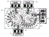
as shown in fig. 1, the automatic detecting and screening system for multiple trays of the present invention includes a feeding device 10, a first discharging device 20, a second discharging device 30, a third discharging device 40, a first detecting unit 50, and a second detecting unit 60.
The feeding device 10 guides an object to be detected into a first rotary disc body of a first detection unit 50, a plurality of phase taking detection devices in the first detection unit 50 around the first rotary disc body shoot the detected object from different directions, the object to be detected enters a second rotary disc body of a second detection unit 60 through a connecting mechanism between the first detection unit 50 and the second detection unit 60, a plurality of phase taking detection devices in the second detection unit 60 around the second rotary disc body also shoot the detected object from different directions, a computer analyzes and judges whether the object to be detected is a good product or a defective product according to pictures shot by the plurality of phase taking detection devices, defective products detected by the first detection unit are fed through a third feeding device 40, defective products detected by the second detection unit are fed through a second feeding device 30, and good products detected by the second detection unit are fed through the first feeding device 20.
The automatic detection and screening system of the multiple conveying discs of the invention has the first invention point that: the invention changes the traditional condition that only one rotary disc body can be used for conveying the detected object, the peripheral space of the rotary disc body is limited, so that the arrangement quantity of the phase taking detection devices is limited, and more different angles can not be arranged for taking pictures of the detected object, therefore, the invention can arrange any number of phase taking detection devices through the combination of a plurality of rotary disc bodies theoretically, and ensures the detection quality.
The third blanking device 40 is provided around the first detection unit 50 in fig. 1, and the detection target determined as a defective product by the first detection unit 50 can be blanked by the third blanking device 40 without entering the second detection unit 60.
As shown in fig. 2, the first detecting unit 50 of the present invention includes a feeding rotary tray 501, a feeding guide 502, and a first rotary tray 500, and a detecting object enters the feeding rotary tray 501 and then enters the first rotary tray 500 through the feeding guide 502 or a mechanical clamping mechanism.
The first rotating tray 500 is rotated by a motor and causes each of the detection objects to sequentially pass through a synchronization guide 503, a guide 504, a fiber positioning device 505, and a plurality of phase taking detection devices. The synchronous guiding device 503 plays a role of guiding the detection object into the set track of the first rotary disk 500, and includes a lower guide wheel, an upper first driving wheel, an upper second driving wheel and a lower third driving wheel, the lower guide wheel is connected with the upper first driving wheel through a first connecting shaft, the upper second driving wheel is connected with the lower third driving wheel through a second connecting shaft, the upper first driving wheel is connected with the upper second driving wheel through a belt, the lower third driving wheel is driven by the first rotary disk 500, the lower guide wheel arranges the detection object according to the set track, and the driving source of the lower guide wheel is the first rotary disk 500, so that the lower guide wheel and the first rotary disk can synchronously move, and the detection object can be ensured to stably run on the first rotary disk 500. The fiber positioning device 504 numbers each test object for computer identification.
The plurality of phase taking detection devices include a first phase taking detection device 506, a second phase taking detection device 507, a third phase taking detection device 508, a fourth phase taking detection device 509 and a fifth phase taking detection device 510, each phase taking detection device can photograph the detection object relative to the front, the rear, the left, the right, the upper, the lower, the inner peripheral wall or the outer peripheral wall of the detection object, and the phase taking detection devices photographed at each angle are not placed in sequence. If a picture is taken from the lower direction upward, the first rotating disk 500 should be a transparent material.
The first detecting unit 50 is further provided with a discharging clamping device 511 and a discharging rotary disk 512, the discharging clamping device 511 clamps the defective product detecting object on the first rotary disk 500 into the discharging rotary disk 512, and the defective product detecting object in the discharging rotary disk 512 is discharged by the third discharging device 40.
As shown in fig. 2, the second detecting unit 60 of the present invention includes a second rotary table 600, a synchronous guiding device 601, a guiding device 602, an optical fiber positioning device, a plurality of phase-taking detecting devices, a good-product blanking clamping device 612, a good-product blanking rotary table 613, a defective-product blanking rotary table 614, and a defective-product blanking clamping device 615. After entering the second rotating disc 600 through the connection mechanism between the first rotating disc 500 and the second rotating disc 600, the object to be measured sequentially passes through the synchronous guide device 601, the guide device 602, the optical fiber positioning device and the plurality of phase taking detection devices, and finally enters the product discharging rotating disc 613 through the good product discharging clamping device 612 or enters the defective product discharging rotating disc 614 through the defective product discharging clamping device 615.
The synchronous guiding device 601 plays a role of guiding a detection object into a set track of the second rotary disc body 600, and comprises a lower guide wheel, an upper first driving wheel, an upper second driving wheel and a lower third driving wheel, wherein the lower guide wheel is connected with the upper first driving wheel through a first connecting shaft, the upper second driving wheel is connected with the lower third driving wheel through a second connecting shaft, the upper first driving wheel is in transmission with the upper second driving wheel through a belt, the lower third driving wheel is driven by the rotary second rotary disc body 600, the lower guide wheel arranges the detection object according to a set track, and a driving source of the lower guide wheel is the second rotary disc body 600, so that the lower guide wheel and the second rotary disc body can synchronously move, and the detection object can be ensured to stably run on the second rotary disc body 600.
The plurality of phase-taking detection means includes a sixth phase-taking detection means 603, a seventh phase-taking detection means 604, an eighth phase-taking detection means 605, a ninth phase-taking detection means 606, a tenth phase-taking detection means 607, an eleventh phase-taking detection means 608, a twelfth phase-taking detection means 609, a thirteenth phase-taking detection means 610, and a fourteenth phase-taking detection means 611. Each of the plurality of photographing detecting means may photograph the subject with respect to the front, rear, left, right, upper, lower, inner circumferential wall or outer circumferential wall of the subject, and the photographing detecting means for photographing at each angle may be placed out of order. The second rotating disk body 600 should be a transparent material if a picture is taken from below upwards.
The good product unloading clamping device 612 clamps the good product inspection object on the second rotary table 600 to the good product unloading rotary table 613, and the defective product unloading clamping device 615 clamps the defective product inspection object on the second rotary table 600 to the defective product unloading rotary table 614.
As shown in fig. 3, the connection mechanism between the first rotating disc 500 and the second rotating disc 600 is the connection direction changing mechanism 70, and the connection direction changing mechanism 70 not only can move the detection object from the first rotating disc 500 to the second rotating disc 600, but also can rotate the detection object by an angle, so that the phase taking detection device around the second rotating disc 600 can take the picture of the detection object after the angle is changed, thereby improving the detection accuracy and precision and avoiding the missing detection or the error detection caused by the dead zone of the photo taking.
The connecting direction changing mechanism 70 comprises a conveyor belt 700, the conveyor belt 700 is arranged on a conveyor belt supporting frame 704, a first guide block 701 is arranged at the connecting end of the conveyor belt 700 and the first rotary disc body 500, the first guide block 701 comprises a first guide oblique edge 702 and a first guide straight edge 703, the first guide oblique edge 702 serves to redirect the detection object on the first rotary disc body 500 to the conveyor belt 700, and the first guide straight edge 703 ensures that the detection object moves linearly on the conveyor belt 700.
A second guide block 705 is arranged at the connecting end of the conveyor belt 700 and the second rotary disc body 600, the second guide block 705 comprises a second guide straight edge 706, a second guide oblique edge 707 and a direction-changing oblique edge 708, the second guide straight edge 706 ensures that the detection object moves linearly on the conveyor belt 700, the second guide oblique edge 707 enables the detection object to shift towards the direction of the second rotary disc body 600, the direction-changing oblique edge 708 enables the detection object to rotate by an angle, and then the detection object enters the second rotary disc body 600, and the angle is 90 degrees, and other angle values can also be provided.
The transmission structure of the conveyor belt 700 comprises a motor 709, a driving wheel 710, a belt 711 and a transmission wheel 712, wherein a rotor of the motor 709 is connected with the driving wheel 710, the driving wheel 710 is connected with the transmission wheel 712 through the belt, and the transmission wheel 712 is connected with one belt pulley of the conveyor belt 700 through a connecting shaft.
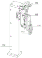
As shown in fig. 4, the feeding device 10 is identical to the discharging device in terms of mechanical structure, and the difference between the two is that the discharging is the reverse process of the feeding. The feeding device of the invention feeds and discharges the detection object through the mechanical clamping jaw, thereby avoiding the damage of the vibration generated by the vibration disc to the detection object during feeding and also avoiding harmful dust blown into the detection object by blowing during discharging.
Specifically, the gripping device of the feeding device 10 includes a linear motion clamping jaw 104, the linear motion clamping jaw 104 is used for gripping and putting down the detection object through a clamping jaw cylinder 105, the linear motion clamping jaw 104 can realize free movement in the horizontal direction and the vertical direction, the horizontal movement of the linear motion clamping jaw is realized through a horizontal moving device, the horizontal moving device includes a horizontal moving platform 101 and a horizontal moving support 102, the clamping jaw is installed on the horizontal moving support 102, and the horizontal moving support 102 is moved in the horizontal direction relative to the horizontal moving platform 101 under the action of a motor 100. The vertical movement is realized by a first vertical moving mechanism 103, the first vertical moving mechanism 103 is installed on the horizontal moving support 102, and the first vertical moving mechanism 103 is a cylinder and directly acts on the linear moving clamping jaw 104 to make the linear moving clamping jaw move in the vertical direction.
Since some inspection objects (e.g., cell phone camera motors) have a non-planar surface that does not contact the spin bowl or otherwise cause phase distortion, the surface should be facing upward. Meanwhile, the detection object is placed on the tray in a non-planar downward mode, so that the detection object with the uneven surface facing downward needs to be placed on the rotary pot body after the uneven surface faces upward through rotation of the rotary moving clamping jaw 108, or reverse operation is carried out during blanking.
The rotary motion clamping jaw 108 comprises two clamping arms, an upper clamping jaw 109 is formed at the upper end of each clamping arm, a lower clamping jaw 110 is formed at the lower end of each clamping arm, and the clamping jaw rotary air 107 enables the upper clamping jaw 109 and the lower clamping jaw 110 to work synchronously by acting on the two clamping arms, simultaneously grabs a detection object, or simultaneously puts down the detection object, so that the working efficiency is improved.
The rotating moving jaw 108 is moved in a tapered direction by a second vertical moving mechanism 106, and the second vertical moving mechanism 106 may be an air cylinder or a motor.
Both the linearly moving jaw 104 and the rotationally moving jaw 108 are connected to a support bracket 111, and the support bracket 111 is mounted on a mounting platform of the first detection unit 50 and/or the second detection unit 60.
The working process is as follows: during feeding, the linear moving clamping jaw 104 moves to the upper part of the feeding machine firstly, then descends to clamp a detection object from the material box, then vertically ascends, horizontally moves to the upper part of the rotary moving clamping jaw 108, the linear moving clamping jaw 104 descends to place the detection object on the upper clamping jaw 109 of the rotary moving clamping jaw, and the rotary moving clamping jaw rotates 180 degrees, so that the detection object also changes 180 degrees and moves from the upper part to the lower part, and the detection object is enabled to face upwards in an uneven mode. The upper jaw 109 is opened so that the inspection object falls on the feeding rotary tray 501. When blanking, the whole process is opposite.
As shown in fig. 5, the blanking taking device 511, the good product blanking taking device 612 and the defective product blanking taking device 615 have the same structure and the same function of transferring the good products or the defective products from the first rotating disc or the second rotating disc to the blanking rotating disc.
The linear motion clamping jaw 113 comprises a linear motion clamping jaw 113, the linear motion clamping jaw 113 is used for grabbing or putting down a detection object through a clamping jaw air cylinder 114, the linear motion clamping jaw 113 is used for realizing the movement in the horizontal direction through a horizontal moving air cylinder 116, and the linear motion clamping jaw 113 is used for realizing the movement in the vertical direction through a vertical moving air cylinder 115.
The horizontal movement cylinder 116 is connected to the upper end of the bracket 112, and the lower end of the bracket 112 is fixed to the mounting platform of the first detection unit 50 and/or the second detection unit 60.
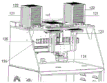
As shown in fig. 6, a tray support 122 is provided on the box 120 of the loading device 10, an internal space of the tray support 122 forms a stacking space of the trays 121, and an internal space of the tray support 122 is communicated with the inside of the box 120.
Two tray supports 122 are arranged on the box body 120, a feeding and discharging area 127 is arranged between the two tray supports 122, a tray 121 is placed in the feeding and discharging area 127, and the tray 121 is used for placing a detection object.
As shown in fig. 7, a tray moving mechanism is disposed in the box 120 of the feeding device 10, and the tray moving mechanism includes a first servo motor 124, a second servo motor 126 and a moving bracket 123.
The first servo motor 124 moves the moving bracket 123 by a screw action so that the moving bracket 123 moves up and down in a vertical direction and places or leaves the tray 121 on the moving bracket 123 on or off the tray bracket 122 or causes the tray 121 to enter or leave a loading and unloading area 127 of a product. The second servo motor 126 moves the moving bracket 123 through another screw rod, so that the moving bracket 123 moves left and right in the horizontal direction to a position right below the tray bracket 122 or a position right below the loading and unloading area 127.
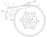
As shown in fig. 8, the feeding guide device 502 includes a first guide portion a located on the first rotary disk 500 and a second guide portion B located on the feeding rotary disk 501, the second guide portion B is used for changing the direction of the detection object and entering the detection object onto one rotary disk a, and the first guide portion a is tangent to the other rotary disk B to ensure that the detection object moves according to a set track.
The invention is described above with reference to the accompanying drawings, it is obvious that the implementation of the invention is not limited in the above manner, and it is within the scope of the invention to adopt various modifications of the inventive method concept and solution, or to apply the inventive concept and solution directly to other applications without modification.
Claims (10)
1. The utility model provides an automated inspection screening system of many delivery trays which characterized in that: the device comprises a feeding device (10), a plurality of blanking devices and at least two detection units, wherein the feeding device (10) guides an object to be detected into a first rotary disc body (500) of a first detection unit (50), a plurality of phase taking detection devices around the first rotary disc body (500) photograph the object to be detected from different directions, the object to be detected enters a second rotary disc body (600) of a second detection unit (60) from the first rotary disc body (500) of the first detection unit (50) through a connecting mechanism, the plurality of phase taking detection devices around the second rotary disc body (600) photograph the object to be detected from different directions, a computer analyzes and judges whether the object to be detected is a good product or a defective product according to pictures shot by the plurality of phase taking detection devices, and the defective product detected by the first detection unit (50) is blanked through a third blanking device (40), the defective products detected by the second detection unit (60) are discharged through the second discharging device (30), and the good products detected by the second detection unit are discharged through the first discharging device (20);
the connecting mechanism is connected with a direction changing mechanism (70) to enable a detection object to rotate by an angle, and a phase taking detection device on the periphery of the second rotating disc body (600) can take a picture of the detection object after the angle is changed; the connecting direction changing mechanism (70) comprises a conveyor belt (700), the conveyor belt (700) is arranged on a conveyor belt supporting frame (704), a first guide block (701) is arranged at the connecting end of the conveyor belt (700) and the first rotating disc body (500), the first guide block (701) comprises a first guide oblique edge (702) and a first guide straight edge (703), the first guide oblique edge (702) guides a detection object on the first rotating disc body (500) to enter the conveyor belt (700), and the first guide straight edge (703) ensures that the detection object moves linearly on the conveyor belt (700); the detection device is characterized in that a second guide block (705) is arranged at the connecting end of the conveyor belt (700) and the second rotary disc body (600), the second guide block (705) comprises a second guide straight edge (706), a second guide oblique edge (707) and a direction-changing oblique edge (708), the second guide straight edge (706) ensures that a detection object moves linearly on the conveyor belt (700), the detection object shifts towards the direction of the second rotary disc body (600) due to the second guide oblique edge (707), and the detection object enters the second rotary disc body (600) after rotating for an angle due to the direction-changing oblique edge (708).
2. The automatic inspection screening system of claim 1, wherein:
the angle is 90 °;
and/or the first and/or second light sources,
the transmission structure of conveyer belt (700) includes motor (709), drive wheel (710), belt (711) and drive wheel (712), the rotor of motor (709) with drive wheel (710) are connected, drive wheel (710) pass through belt (711) with drive wheel (712) are connected, drive wheel (712) with a belt pulley of conveyer belt (700) passes through the connecting axle and connects.
3. The automatic inspection screening system of multi-feed tray according to claim 1 or 2, wherein: when the number of the detection units is N, N is more than 2, N-1 connecting mechanisms exist, and the N-1 connecting mechanisms connect the N detection units in series.
4. The automatic inspection screening system of a plurality of feed trays according to any one of claims 1 to 3, wherein: the first rotary disc body (500) or the second rotary disc body (600) rotates and enables each detection object to sequentially pass through the synchronous guiding device, the optical fiber positioning device and the plurality of phase taking detection devices.
5. The automatic inspection screening system of claim 4, wherein: each of the plurality of photographing detecting means may photograph the subject with respect to the front, rear, left, right, upper, lower, obliquely upper left, obliquely upper right, obliquely lower left, obliquely lower right, inner peripheral wall or outer peripheral wall of the subject, and the photographing detecting means for photographing at each angle is placed without precedence.
6. The automatic inspection screening system of multi-feed tray according to claim 4 or 5, wherein: the feeding device (10) comprises a linear motion clamping jaw, and the linear motion clamping jaw can move horizontally or vertically and directly transfer a detection object to the first rotating disc body (500) from a static tray or firstly transfer the detection object to the first rotating disc body (501), and then transfer the detection object to the first rotating disc body (500) from the first rotating disc body (501).
7. The automatic inspection screening system of claim 6, wherein: the feeding device (10) further comprises a rotary moving clamping jaw (108), and the rotary moving clamping jaw (108) enables the detection object to rotate by an angle to ensure that the contact surface of the detection object and the feeding rotary disc body (501) or the first rotary disc body (500) is a plane.
8. The automatic inspection screening system of claim 7, wherein: a feeding guide device (502) is arranged between the feeding rotary disc body (501) and the first rotary disc body (500) to transfer the detection object from the feeding rotary disc body (501) to the first rotary disc body (500).
9. The automatic inspection screening system of claim 8, wherein: a tray moving mechanism is arranged in a box body (120) of the feeding device (10), the tray moving mechanism comprises a first servo motor (124), a second servo motor (126) and a moving support (123), the first servo motor (124) moves the moving support (123) through the action of a screw rod so that the moving support (123) moves up and down in the vertical direction, and the tray (121) on the moving support (123) is placed on or separated from the tray support (122) or the tray (121) enters or separates from a feeding and discharging area (127) of a product; the second servo motor (126) moves the movable support (123) through the action of the other screw rod, so that the movable support (123) moves left and right in the horizontal direction to be right below the tray support (122) or right below the feeding and discharging area (127).
10. The automatic inspection screening system of a plurality of feed trays according to any one of claims 1 to 9, wherein: the first blanking device (20), the second blanking device (30) or/and the third blanking device (40) have the same structure as the feeding device (10).
Priority Applications (1)
| Application Number | Priority Date | Filing Date | Title |
|---|---|---|---|
| CN202010415398.0A CN111715558B (en) | 2019-03-07 | 2019-03-07 | Automatic detection and screening system with multiple conveying discs |
Applications Claiming Priority (2)
| Application Number | Priority Date | Filing Date | Title |
|---|---|---|---|
| CN201910170031.4A CN109894375B (en) | 2019-03-07 | 2019-03-07 | Connecting and direction-changing mechanism among multiple conveying discs of automatic detection and screening system |
| CN202010415398.0A CN111715558B (en) | 2019-03-07 | 2019-03-07 | Automatic detection and screening system with multiple conveying discs |
Related Parent Applications (1)
| Application Number | Title | Priority Date | Filing Date |
|---|---|---|---|
| CN201910170031.4A Division CN109894375B (en) | 2019-03-07 | 2019-03-07 | Connecting and direction-changing mechanism among multiple conveying discs of automatic detection and screening system |
Publications (2)
| Publication Number | Publication Date |
|---|---|
| CN111715558A true CN111715558A (en) | 2020-09-29 |
| CN111715558B CN111715558B (en) | 2022-11-29 |
Family
ID=66946696
Family Applications (2)
| Application Number | Title | Priority Date | Filing Date |
|---|---|---|---|
| CN201910170031.4A Active CN109894375B (en) | 2019-03-07 | 2019-03-07 | Connecting and direction-changing mechanism among multiple conveying discs of automatic detection and screening system |
| CN202010415398.0A Active CN111715558B (en) | 2019-03-07 | 2019-03-07 | Automatic detection and screening system with multiple conveying discs |
Family Applications Before (1)
| Application Number | Title | Priority Date | Filing Date |
|---|---|---|---|
| CN201910170031.4A Active CN109894375B (en) | 2019-03-07 | 2019-03-07 | Connecting and direction-changing mechanism among multiple conveying discs of automatic detection and screening system |
Country Status (1)
| Country | Link |
|---|---|
| CN (2) | CN109894375B (en) |
Families Citing this family (2)
| Publication number | Priority date | Publication date | Assignee | Title |
|---|---|---|---|---|
| CN111144478B (en) * | 2019-12-25 | 2022-06-14 | 电子科技大学 | Automatic detection method for through lens |
| CN113466415B (en) * | 2021-07-09 | 2023-05-16 | 河南省保时安电子科技有限公司 | Detection device for screening quality of gas sensor |
Citations (10)
| Publication number | Priority date | Publication date | Assignee | Title |
|---|---|---|---|---|
| JP2000264436A (en) * | 1999-03-16 | 2000-09-26 | Okamura Corp | Direction-change device for carried material |
| JP2001096234A (en) * | 1999-09-30 | 2001-04-10 | Kubota Corp | Waste sorting device |
| JP2008073626A (en) * | 2006-09-22 | 2008-04-03 | Nitto Seiko Co Ltd | Part inspection device |
| CN201932689U (en) * | 2010-12-27 | 2011-08-17 | 天津滨海国际花卉科技园区股份有限公司 | Reversed conveying device for potted flower trays of greenhouse |
| CN104029982A (en) * | 2013-03-05 | 2014-09-10 | 常州江润精密机械有限公司 | Automatic bottle detection production line |
| CN204848214U (en) * | 2015-06-10 | 2015-12-09 | 常州市苏鑫制药机械有限公司 | Rotatory tracking formula liquid filling machine |
| CN205022002U (en) * | 2015-09-24 | 2016-02-10 | 佛冈给力机械有限公司 | Full -automatic double plate of rotation type is detained machine of leaking hunting |
| CN105744926A (en) * | 2013-08-09 | 2016-07-06 | 珀赛普蒂迈德股份有限公司 | Pill feeder |
| CN105817431A (en) * | 2016-05-07 | 2016-08-03 | 肇庆市宏华电子科技有限公司 | Intelligent appearance defect high-speed detection machine |
| CN207957001U (en) * | 2018-03-22 | 2018-10-12 | 中山天聚自动化输送设备有限公司 | Product changement on pipeline |
Family Cites Families (5)
| Publication number | Priority date | Publication date | Assignee | Title |
|---|---|---|---|---|
| DE4202172C1 (en) * | 1992-01-27 | 1993-03-11 | Josef 8933 Graben De Fischer | Testing surface and shape of similar small objects e.g. medicinal tabless - directing cameras onto rotatable discs with recesses for objects quality control |
| CN203877448U (en) * | 2014-06-05 | 2014-10-15 | 云南昆船设计研究院 | Sorting reversing device |
| CN205873235U (en) * | 2016-06-27 | 2017-01-11 | 东莞兆泰机械设备有限公司 | Material conveyer device |
| CN106623004A (en) * | 2017-01-24 | 2017-05-10 | 浙江四点灵机器人股份有限公司 | High-precision optical detector |
| CN108116866B (en) * | 2018-02-01 | 2024-03-22 | 苏州杰锐思智能科技股份有限公司 | Automatic arrangement discharging device |
-
2019
- 2019-03-07 CN CN201910170031.4A patent/CN109894375B/en active Active
- 2019-03-07 CN CN202010415398.0A patent/CN111715558B/en active Active
Patent Citations (10)
| Publication number | Priority date | Publication date | Assignee | Title |
|---|---|---|---|---|
| JP2000264436A (en) * | 1999-03-16 | 2000-09-26 | Okamura Corp | Direction-change device for carried material |
| JP2001096234A (en) * | 1999-09-30 | 2001-04-10 | Kubota Corp | Waste sorting device |
| JP2008073626A (en) * | 2006-09-22 | 2008-04-03 | Nitto Seiko Co Ltd | Part inspection device |
| CN201932689U (en) * | 2010-12-27 | 2011-08-17 | 天津滨海国际花卉科技园区股份有限公司 | Reversed conveying device for potted flower trays of greenhouse |
| CN104029982A (en) * | 2013-03-05 | 2014-09-10 | 常州江润精密机械有限公司 | Automatic bottle detection production line |
| CN105744926A (en) * | 2013-08-09 | 2016-07-06 | 珀赛普蒂迈德股份有限公司 | Pill feeder |
| CN204848214U (en) * | 2015-06-10 | 2015-12-09 | 常州市苏鑫制药机械有限公司 | Rotatory tracking formula liquid filling machine |
| CN205022002U (en) * | 2015-09-24 | 2016-02-10 | 佛冈给力机械有限公司 | Full -automatic double plate of rotation type is detained machine of leaking hunting |
| CN105817431A (en) * | 2016-05-07 | 2016-08-03 | 肇庆市宏华电子科技有限公司 | Intelligent appearance defect high-speed detection machine |
| CN207957001U (en) * | 2018-03-22 | 2018-10-12 | 中山天聚自动化输送设备有限公司 | Product changement on pipeline |
Also Published As
| Publication number | Publication date |
|---|---|
| CN109894375B (en) | 2020-04-03 |
| CN109894375A (en) | 2019-06-18 |
| CN111715558B (en) | 2022-11-29 |
Similar Documents
| Publication | Publication Date | Title |
|---|---|---|
| CN109985820B (en) | Automatic detection and screening system with multiple conveying discs | |
| CN105798609B (en) | Limit switch kludge | |
| CN100459034C (en) | Full-automatic wafer rear marking machine | |
| CN109894375B (en) | Connecting and direction-changing mechanism among multiple conveying discs of automatic detection and screening system | |
| CN109821773B (en) | Feeding and discharging device of automatic detection screening system | |
| CN107344635A (en) | A kind of clinical thermometer labeling packing machine and its labeling packing method | |
| CN108593677A (en) | A kind of special-shaped part full-automatic vision detection device | |
| CN212310150U (en) | Image acquisition rotary platform of automatic product detection and screening device | |
| CN207089715U (en) | A kind of clinical thermometer labels packing machine | |
| CN112828589A (en) | Camera module assembling equipment and assembling process thereof | |
| CN218531858U (en) | Visual inspection equipment for surface defects of workpiece | |
| CN209280579U (en) | Jewelry appearance precision detection equipment | |
| CN116443545B (en) | 360 unloading outward appearance detects machine in degree integration | |
| CN218968179U (en) | Feeding device | |
| CN220584083U (en) | Chip outward appearance AOI check out test set | |
| CN114919939B (en) | Inductance detection device | |
| CN218460171U (en) | Continuous detection device of valve size based on machine vision | |
| CN114226266B (en) | Roller neglected loading and flip-chip integrated detection equipment for tapered roller bearing | |
| CN218753196U (en) | High-speed carrying device | |
| CN218902751U (en) | Appearance detection device without interval | |
| CN112917147B (en) | Clamping mechanism for assembling camera module and turntable assembling device | |
| CN219310616U (en) | Automatic assembly line for display screen | |
| CN213445083U (en) | Apron fine positioning material loading machine | |
| CN219607952U (en) | Screw detects machine | |
| CN116908195B (en) | Automatic broken piece detection equipment |
Legal Events
| Date | Code | Title | Description |
|---|---|---|---|
| PB01 | Publication | ||
| PB01 | Publication | ||
| SE01 | Entry into force of request for substantive examination | ||
| SE01 | Entry into force of request for substantive examination | ||
| GR01 | Patent grant | ||
| GR01 | Patent grant |