CN111713381B - Irrigation system is collected to energy-saving gardens rainwater - Google Patents
Irrigation system is collected to energy-saving gardens rainwater Download PDFInfo
- Publication number
- CN111713381B CN111713381B CN202010603729.3A CN202010603729A CN111713381B CN 111713381 B CN111713381 B CN 111713381B CN 202010603729 A CN202010603729 A CN 202010603729A CN 111713381 B CN111713381 B CN 111713381B
- Authority
- CN
- China
- Prior art keywords
- water
- pipe
- tank
- spray
- irrigation
- Prior art date
- Legal status (The legal status is an assumption and is not a legal conclusion. Google has not performed a legal analysis and makes no representation as to the accuracy of the status listed.)
- Active
Links
Images


Classifications
-
- A—HUMAN NECESSITIES
- A01—AGRICULTURE; FORESTRY; ANIMAL HUSBANDRY; HUNTING; TRAPPING; FISHING
- A01G—HORTICULTURE; CULTIVATION OF VEGETABLES, FLOWERS, RICE, FRUIT, VINES, HOPS OR SEAWEED; FORESTRY; WATERING
- A01G25/00—Watering gardens, fields, sports grounds or the like
- A01G25/02—Watering arrangements located above the soil which make use of perforated pipe-lines or pipe-lines with dispensing fittings, e.g. for drip irrigation
-
- C—CHEMISTRY; METALLURGY
- C02—TREATMENT OF WATER, WASTE WATER, SEWAGE, OR SLUDGE
- C02F—TREATMENT OF WATER, WASTE WATER, SEWAGE, OR SLUDGE
- C02F1/00—Treatment of water, waste water, or sewage
- C02F1/001—Processes for the treatment of water whereby the filtration technique is of importance
-
- C—CHEMISTRY; METALLURGY
- C02—TREATMENT OF WATER, WASTE WATER, SEWAGE, OR SLUDGE
- C02F—TREATMENT OF WATER, WASTE WATER, SEWAGE, OR SLUDGE
- C02F1/00—Treatment of water, waste water, or sewage
- C02F1/52—Treatment of water, waste water, or sewage by flocculation or precipitation of suspended impurities
-
- E—FIXED CONSTRUCTIONS
- E03—WATER SUPPLY; SEWERAGE
- E03B—INSTALLATIONS OR METHODS FOR OBTAINING, COLLECTING, OR DISTRIBUTING WATER
- E03B3/00—Methods or installations for obtaining or collecting drinking water or tap water
- E03B3/02—Methods or installations for obtaining or collecting drinking water or tap water from rain-water
-
- E—FIXED CONSTRUCTIONS
- E03—WATER SUPPLY; SEWERAGE
- E03F—SEWERS; CESSPOOLS
- E03F5/00—Sewerage structures
- E03F5/10—Collecting-tanks; Equalising-tanks for regulating the run-off; Laying-up basins
-
- F—MECHANICAL ENGINEERING; LIGHTING; HEATING; WEAPONS; BLASTING
- F21—LIGHTING
- F21S—NON-PORTABLE LIGHTING DEVICES; SYSTEMS THEREOF; VEHICLE LIGHTING DEVICES SPECIALLY ADAPTED FOR VEHICLE EXTERIORS
- F21S9/00—Lighting devices with a built-in power supply; Systems employing lighting devices with a built-in power supply
- F21S9/02—Lighting devices with a built-in power supply; Systems employing lighting devices with a built-in power supply the power supply being a battery or accumulator
- F21S9/03—Lighting devices with a built-in power supply; Systems employing lighting devices with a built-in power supply the power supply being a battery or accumulator rechargeable by exposure to light
- F21S9/035—Lighting devices with a built-in power supply; Systems employing lighting devices with a built-in power supply the power supply being a battery or accumulator rechargeable by exposure to light the solar unit being integrated within the support for the lighting unit, e.g. within or on a pole
-
- F—MECHANICAL ENGINEERING; LIGHTING; HEATING; WEAPONS; BLASTING
- F21—LIGHTING
- F21V—FUNCTIONAL FEATURES OR DETAILS OF LIGHTING DEVICES OR SYSTEMS THEREOF; STRUCTURAL COMBINATIONS OF LIGHTING DEVICES WITH OTHER ARTICLES, NOT OTHERWISE PROVIDED FOR
- F21V19/00—Fastening of light sources or lamp holders
-
- F—MECHANICAL ENGINEERING; LIGHTING; HEATING; WEAPONS; BLASTING
- F21—LIGHTING
- F21V—FUNCTIONAL FEATURES OR DETAILS OF LIGHTING DEVICES OR SYSTEMS THEREOF; STRUCTURAL COMBINATIONS OF LIGHTING DEVICES WITH OTHER ARTICLES, NOT OTHERWISE PROVIDED FOR
- F21V23/00—Arrangement of electric circuit elements in or on lighting devices
- F21V23/02—Arrangement of electric circuit elements in or on lighting devices the elements being transformers, impedances or power supply units, e.g. a transformer with a rectifier
- F21V23/023—Power supplies in a casing
-
- C—CHEMISTRY; METALLURGY
- C02—TREATMENT OF WATER, WASTE WATER, SEWAGE, OR SLUDGE
- C02F—TREATMENT OF WATER, WASTE WATER, SEWAGE, OR SLUDGE
- C02F2103/00—Nature of the water, waste water, sewage or sludge to be treated
- C02F2103/001—Runoff or storm water
-
- F—MECHANICAL ENGINEERING; LIGHTING; HEATING; WEAPONS; BLASTING
- F21—LIGHTING
- F21Y—INDEXING SCHEME ASSOCIATED WITH SUBCLASSES F21K, F21L, F21S and F21V, RELATING TO THE FORM OR THE KIND OF THE LIGHT SOURCES OR OF THE COLOUR OF THE LIGHT EMITTED
- F21Y2115/00—Light-generating elements of semiconductor light sources
- F21Y2115/10—Light-emitting diodes [LED]
-
- Y—GENERAL TAGGING OF NEW TECHNOLOGICAL DEVELOPMENTS; GENERAL TAGGING OF CROSS-SECTIONAL TECHNOLOGIES SPANNING OVER SEVERAL SECTIONS OF THE IPC; TECHNICAL SUBJECTS COVERED BY FORMER USPC CROSS-REFERENCE ART COLLECTIONS [XRACs] AND DIGESTS
- Y02—TECHNOLOGIES OR APPLICATIONS FOR MITIGATION OR ADAPTATION AGAINST CLIMATE CHANGE
- Y02A—TECHNOLOGIES FOR ADAPTATION TO CLIMATE CHANGE
- Y02A20/00—Water conservation; Efficient water supply; Efficient water use
- Y02A20/108—Rainwater harvesting
Landscapes
- Engineering & Computer Science (AREA)
- Life Sciences & Earth Sciences (AREA)
- Water Supply & Treatment (AREA)
- Hydrology & Water Resources (AREA)
- General Engineering & Computer Science (AREA)
- Environmental & Geological Engineering (AREA)
- Chemical & Material Sciences (AREA)
- Public Health (AREA)
- Health & Medical Sciences (AREA)
- Organic Chemistry (AREA)
- Power Engineering (AREA)
- Sustainable Development (AREA)
- Soil Sciences (AREA)
- Environmental Sciences (AREA)
- Sewage (AREA)
- Catching Or Destruction (AREA)
Abstract
The invention provides an energy-saving garden rainwater collecting and irrigating system which comprises a water collecting tank, wherein the water collecting tank is connected to a reservoir through a drain pipe, and the reservoir comprises a sedimentation tank and a clean water tank; the sedimentation tank is internally provided with inclined tube filling; the sedimentation tank and the clean water tank are communicated through an overflow port; a high-pressure water pump is arranged outside the reservoir, a water inlet of the high-pressure water pump is connected to the clean water tank through a water pipe, and a water outlet of the high-pressure water pump is connected to the irrigation system through a water pipe; the irrigation system comprises a plurality of groups of irrigation units, each group of irrigation units comprises a support rod, spray pipes are rotatably mounted on the support rods, spray heads are arranged on the spray pipes, the spray pipes are connected through a buckle type rotary joint, and one end of each spray pipe of one group of irrigation units is connected with a water pipe through the buckle type rotary joint; the spray pipe is provided with a toothed belt, the support rod is provided with a servo motor, and the output end of the servo motor is provided with a driving gear. The rainwater storage and cleaning device can efficiently clean and store rainwater, efficiently utilize the rainwater on the premise of energy conservation, and is high in practicability.
Description
Technical Field
The invention relates to the technical field of garden construction, in particular to an energy-saving garden rainwater collecting and irrigating system.
Background
China is a country with quite a shortage of water resources, irrigation of gardens needs to consume a large amount of water resources, nearby river water is generally used for irrigation of gardens, but a part of greening places such as lawns and flower beds are far away from the river edge and need to be transported by vehicles, and a large amount of financial resources and manpower are consumed. At this moment, the rainwater can satisfy the treegarden irrigation of certain degree, saves a large amount of manpower and material resources, but the rainwater is difficult to remain for a long time, and the utilization ratio is lower, and when utilizing untreated rainwater to irrigate gardens vegetation, impurity blocks up the water utensil easily, influences irrigation efficiency, has the risk of equipment damage even.
Disclosure of Invention
The invention aims to overcome the defects of the prior art and provides a water-saving garden water storage irrigation system capable of collecting, cleaning and efficiently utilizing rainwater, which has the following specific scheme:
an energy-saving garden rainwater collection and irrigation system comprises a water collection tank, wherein the water collection tank is connected to a water storage tank through a water drainage pipe, and the water storage tank comprises a sedimentation tank and a clean water tank positioned outside the sedimentation tank; an inclined tube filler for accelerating the precipitation separation of sewage is arranged in the sedimentation tank; the sedimentation tank and the clean water tank are communicated through an overflow port, and a filter screen is arranged at the overflow port; a high-pressure water pump is arranged outside the reservoir, a water inlet of the high-pressure water pump is connected to the bottom of the clean water reservoir through a water pipe, and a water outlet of the high-pressure water pump is connected to an irrigation system through a water pipe; the irrigation system comprises a plurality of groups of irrigation units, each group of irrigation units comprises a support rod arranged on the ground, spray pipes are rotatably arranged on the support rods through bearings, a plurality of spray heads are arranged on the spray pipes, the spray pipes of two adjacent groups of irrigation units are connected through a buckle type rotary joint, and one end of each spray pipe of one group of irrigation units is connected with the water pipe through the buckle type rotary joint; the spray pipe is annularly provided with a toothed belt, the support rod is provided with a servo motor, the output end of the servo motor is provided with a driving gear meshed with the toothed belt, and the servo motor is electrically connected to a control module arranged on the support rod; a first storage battery for supplying power to the high-pressure water pump is arranged outside the water storage tank; a waterwheel corresponding to the drain pipe is arranged in the sedimentation tank, the waterwheel is driven by water discharged by the drain pipe to rotate anticlockwise, and a generator for supplying power to the first storage battery is arranged on the waterwheel in a linkage manner; the bottom of the sedimentation tank slants downwards in an inclined way along the rotation direction of the waterwheel, a mud groove is arranged at the lowest position of the bottom of the sedimentation tank, a mud level meter is arranged in the mud groove, a sludge pump is arranged below the sedimentation tank, a mud inlet of the sludge pump is connected to the mud groove through a sludge pipe, and a mud outlet of the sludge pump is connected to a sludge tank arranged outside the reservoir through a sludge pipe; the upper portion of drain pipe is equipped with charge device, charge device includes the casing, be equipped with the pivot in the casing, be equipped with many puddlers in the pivot, be equipped with the otter board on the puddler, the pivot is driven by the agitator motor who sets up in the casing top, has seted up the charge door on the casing, the below of casing be equipped with the unloading pipe of drain pipe intercommunication, be equipped with the third battery valve in the unloading pipe.
Based on the above, agitator motor, third solenoid valve, sludge pump, mud level meter and high-pressure water pump all electric connection to controller.
Based on the above, still be equipped with in the drain pipe with controller electric connection's rivers sensor.
Based on the aforesaid, be close to in the drain pipe cistern department is equipped with the mixed flow structure, the mixed flow structure is including two sets of vortex blades, two sets of that laminating drain pipe inner wall set up the water conservancy diversion opposite direction of vortex blade.
Based on the above, two first electromagnetic valves are arranged inside the spray pipe, and the plurality of spray heads are arranged between the two electromagnetic valves; the spray pipe is also provided with a branch pipe, two ends of the branch pipe are respectively connected to the positions, located on the outer sides of the two first electromagnetic valves, of the spray pipe, and a second electromagnetic valve is arranged in the branch pipe; the first electromagnetic valve and the second electromagnetic valve are both electrically connected to the control module.
Based on the above, the support rod is provided with the support plate, the LED lamp is arranged below the support plate, the support plate is provided with the second storage battery for supplying power to the irrigation unit where the support plate is located, and the support plate is also provided with the solar cell panel for supplying power to the second storage battery through the bracket; the LED lamp is electrically connected to the control module, the control module comprises a photosensitive switch and an infrared induction switch, the photosensitive switch and the infrared induction switch control the LED lamp to be switched on and off, and the photosensitive switch and the infrared induction switch are connected in series.
Based on the above, equidistant screen cloth that is used for filtering impurity is equipped with in the water catch bowl.
Compared with the prior art, the invention has substantive characteristics and progress, and particularly has the following advantages:
1. according to the invention, the screen is arranged in the water collecting tank, so that impurities mixed in the rainwater can be primarily filtered.
2. According to the invention, the dosing device is arranged above the drain pipe, so that the flocculating agent can be added into the rainwater through the structure, and in addition, the mixed flow structure is also arranged in the drain pipe, so that the structure design is beneficial to fully mixing the flocculating agent with the rainwater, and the impurity precipitation efficiency in the rainwater is improved.
3. In addition, the rotation direction of the waterwheel faces to the lower part of the bottom of the sedimentation tank, so that the accumulation of sludge can be accelerated, and the sludge can be conveniently discharged in time.
4. According to the invention, the spray pipe is rotatably arranged on the support rod, the spray pipe is connected with the spray pipe through the buckle type rotary joint, the support rod is also provided with the servo motor for driving the spray pipe to rotate, and the structural design ensures that the irrigation system has a water-saving effect while ensuring the irrigation effect; and, the inside of spray tube is equipped with two first solenoid valves, and the shower nozzle all sets up between two solenoid valves, still is equipped with the branch pipe on the spray tube, and the both ends of branch pipe are connected to and lie in two first solenoid valve outside positions on the spray tube respectively, are equipped with the second solenoid valve in the branch pipe, and this structural design makes the work of shower nozzle selectivity, and then promotes the efficiency of water conservation.
5. In the invention, the LED lamp is controlled by the photosensitive switch and the infrared inductive switch which are connected in series, so that the energy-saving effect of the LED lamp is fully embodied.
Drawings
Fig. 1 is a front view of the overall structure of the present invention.
Fig. 2 is a schematic diagram of the construction of the irrigation system of the present invention.
FIG. 3 is a schematic view of the structure of the stirring apparatus of the present invention.
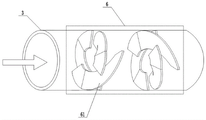
FIG. 4 is a schematic diagram of the mixed flow structure of the present invention.
In the figure: 1. a water collection tank; 2. screening a screen; 3. a drain pipe; 4. a water flow sensor; 5. a dosing device; 51. a housing; 52. a rotating shaft; 53. a stirring rod; 54. a screen plate; 55. a stirring motor; 56. a support frame; 57. a feed inlet; 58. a discharging pipe; 59. a third electromagnetic valve; 6. a mixed flow structure; 61. a spoiler blade; 7. a reservoir; 8. a sedimentation tank; 81. a mud tank; 9. a clean water tank; 10. a filter screen; 11. water wheel; 12. a generator; 13. filling the inclined tube; 14. a mud level meter; 15. a sludge pump; 16. a sludge pipe; 17. a sludge tank; 18. a first storage battery; 19. a controller; 20. a high pressure water pump; 201. a water inlet; 202. a water outlet; 21. a water pipe; 22. an irrigation system; 220. a ground surface; 221. a support bar; 222. a nozzle; 223. a spray head; 224. a first solenoid valve; 225. a branch pipe; 226. a second solenoid valve; 227. a snap-in rotary joint; 228. a bearing; 229. a toothed belt; 230. a servo motor; 231. a drive gear; 232. an LED lamp; 233. a support plate; 234. a second storage battery; 235. a solar panel; 236. a support; 237. and a control module.
Detailed Description
The technical solution of the present invention is further described in detail by the following embodiments.
Examples
As shown in fig. 1-4, the invention provides an energy-saving garden rainwater collection and irrigation system 22, which comprises a water collection tank 1, wherein the water collection tank 1 is connected to a water storage tank 7 through a water discharge pipe 3, and the water storage tank 7 comprises a sedimentation tank 8 and a clean water tank 9 positioned outside the sedimentation tank 8.
In order to remove impurities carried by rainwater in the water collecting tank 1, screens 2 for filtering the impurities are arranged in the water collecting tank 1 at equal intervals.
An inclined tube filler 13 for accelerating the precipitation separation of the sewage is arranged in the sedimentation tank 8; the sedimentation tank 8 and the clean water tank 9 are communicated through an overflow port, and a filter screen 10 is arranged at the overflow port.
The outside of the reservoir 7 is provided with a high pressure water pump 20, a water inlet 201 of the high pressure water pump 20 is connected to the bottom of the clean water tank 9 through a water pipe 21, and a water outlet 202 of the high pressure water pump 20 is connected to an irrigation system 22 through the water pipe 21.
The irrigation system 22 comprises a plurality of groups of irrigation units, each group of irrigation units comprises a support rod 221 arranged on the ground 220, a spray pipe 222 is rotatably installed on the support rod 221 through a bearing 228, a plurality of spray heads 223 are arranged on the spray pipe 222, the spray pipes 222 of two adjacent groups of irrigation units are connected through a buckle type rotary joint 227, and one end of each spray pipe 222 of one group of irrigation units is connected with the water pipe 21 through the buckle type rotary joint 227.
A toothed belt 229 is arranged on the spray pipe 222 in a surrounding manner, a servo motor 230 is arranged on the support rod 221, a driving gear 231 meshed with the toothed belt 229 is arranged at the output end of the servo motor 230, and the servo motor 230 is electrically connected to a control module 237 arranged on the support rod 221.
A first accumulator 18 for supplying power to the high-pressure water pump 20 is arranged outside the reservoir 7; the sedimentation tank 8 is internally provided with a waterwheel 11 corresponding to the drain pipe 3, the drain pipe 3 discharges water to drive the waterwheel 11 to rotate anticlockwise, and the waterwheel 11 is provided with a generator 12 supplying power to the first storage battery 18 in a linkage manner.
The bottom of the sedimentation tank 8 slants downwards in an inclined manner along the rotation direction of the waterwheel 11, a mud groove 81 is arranged at the lowest position of the bottom of the sedimentation tank 8, a mud level meter 14 is arranged in the mud groove 81, a sludge pump 15 is arranged below the sedimentation tank 8, a mud inlet of the sludge pump 15 is connected to the mud groove 81 through a sludge pipe 16, and a mud outlet of the sludge pump 15 is connected to a sludge tank 17 arranged outside the reservoir 7 through the sludge pipe 16.
In order to further accelerate the purification treatment of the rainwater, a flocculating agent can be added into the rainwater to accelerate the settling speed of impurities in the rainwater, so that a dosing device 5 is arranged at the upper part of the drain pipe 3. The dosing device 5 comprises a shell 51, a rotating shaft 52 is arranged in the shell 51, a plurality of stirring rods 53 are arranged on the rotating shaft 52, a screen plate 54 is arranged on each stirring rod 53, the rotating shaft 52 is driven by a stirring motor 55 arranged above the shell 51, the stirring motor is fixedly arranged on the shell 51 through a supporting frame, a feeding opening 57 is further formed in the shell 51, a discharging pipe 58 communicated with the discharging pipe 3 is arranged below the shell 51, and a third battery valve is arranged in the discharging pipe 58.
The stirring motor 55, the third electromagnetic valve 59, the sludge pump 15, the sludge level meter 14 and the high-pressure water pump 20 are all electrically connected to the controller 19.
In addition, a water flow sensor 4 electrically connected to the controller 19 is provided in the drain pipe 3.
Be close to in drain pipe 37 department of cistern is equipped with mixed flow structure 6, mixed flow structure 6 is including two sets of spoiler blade 61, two sets of that 3 inner walls of laminating drain pipe set up spoiler blade 61's water conservancy diversion opposite direction.
Two first solenoid valves 224 are provided inside the nozzle 222, and a plurality of spray heads 223 are provided between the two solenoid valves. Considering the principle of water saving, the spray head 223 is required to selectively work according to the actual irrigation requirement, so a branch pipe 225 is further arranged on the spray pipe 222, two ends of the branch pipe 225 are respectively connected to the spray pipe 222 at positions outside the two first electromagnetic valves 224, and a second electromagnetic valve 226 is arranged in the branch pipe 225; the first solenoid valve 224 and the second solenoid valve 226 are electrically connected to the control module 237.
The support rod 221 is provided with a support plate 233, the LED lamp 232 is arranged below the support plate 233, the support plate 233 is provided with a second storage battery 234 for supplying power to the irrigation unit where the support plate 233 is located, and the support plate 233 is further provided with a solar cell panel 235 for supplying power to the second storage battery 234 through a support 236.
The LED lamp 232 is electrically connected to the control module 237, and in consideration of the energy saving principle, the control module 237 includes a photosensitive switch and an infrared inductive switch for controlling the on and off of the LED lamp 232, and the photosensitive switch and the infrared inductive switch are connected in series.
The specific working principle of the invention is as follows: in rainy days, rainwater is firstly collected into the water collecting tank 1, in the flowing process of the water collecting tank 1, impurities such as branches and leaves in rainwater are filtered by the screen 2, the rainwater after primary filtration enters the water storage tank 7 through the drain pipe 3, the rainwater senses that water passes through the water flow sensor 4 when flowing through the drain pipe 3 and transmits signals to the controller 19, the controller 19 starts the stirring motor 55, meanwhile, the third electromagnetic valve 59 is opened to add a flocculating agent with uniform stirring into the drain pipe 3, the liquid medicine flows backwards along with the rainwater after entering the drain pipe 3, under the action of the mixed flow structure 6, the rainwater and the flocculating agent are uniformly mixed, then the rainwater enters the water storage tank 7 and falls on the waterwheel 11 to drive the waterwheel to rotate, impurities in the rainwater are accumulated in the mud tank 81, and the settled clean water flows into the clean water tank 9 through the overflow port.
It should be added that the controller 19 should preset the values of the sludge level measured by the sludge level meter 14, which are required for starting the sludge pump 15 and stopping the sludge pump 15, when the sludge level is higher than a certain value, the controller starts the sludge pump 15, the sludge in the sludge tank 81 is discharged into the sludge tank 17, and when the sludge level is lower than a certain value, the controller 19 stops the sludge pump 15.
When the gardens need to be irrigated, the high-pressure water pump 20 is started, water in the water storage tank 7 enters the irrigation system 22 through the water pipe 21, and the water is sprayed out from the spray head 223 to irrigate the vegetation; it should be noted that, during irrigation, the servo motor 230 can also be started to drive the nozzle 222 to rotate, so as to improve irrigation efficiency on the premise of saving water.
When the irrigation area covered by the spray heads 223 on a certain spray pipe 222 does not need irrigation, the purpose of saving water can be achieved by closing a pair of first electromagnetic valves 224 in the corresponding spray pipe 222 and simultaneously opening a second electromagnetic valve 226 on the branch pipe 225 to selectively close some spray heads 223.
It is worth noting that when a person passes by the support rod 221 at night, the photosensitive switch and the infrared inductive switch in the control module 237 work simultaneously, the LED and the like are turned on for illumination, and after the person is far away from the corresponding control module 237, the corresponding LED lamp 232 is turned off, so that the energy-saving effect is obvious.
Finally, it should be noted that: the above examples are only intended to illustrate the technical solution of the present invention and not to limit it; although the present invention has been described in detail with reference to preferred embodiments, those skilled in the art will understand that: modifications to the specific embodiments of the invention or equivalent substitutions for parts of the technical features may be made; without departing from the spirit of the present invention, it is intended to cover all aspects of the invention as defined by the appended claims.
Claims (7)
1. The utility model provides an irrigation system is collected to energy-saving gardens rainwater which characterized in that: the device comprises a water collecting tank (1), wherein the water collecting tank (1) is connected to a water storage tank (7) through a water discharging pipe (3), and the water storage tank (7) comprises a sedimentation tank (8) and a clean water tank (9) positioned outside the sedimentation tank (8); an inclined tube filler (13) for accelerating the precipitation separation of sewage is arranged in the sedimentation tank (8); the sedimentation tank (8) and the clean water tank (9) are communicated through an overflow port, and a filter screen (10) is arranged at the overflow port; a high-pressure water pump (20) is arranged outside the reservoir (7), a water inlet (201) of the high-pressure water pump (20) is connected to the bottom of the clean water tank (9) through a water pipe (21), and a water outlet (202) of the high-pressure water pump (20) is connected to an irrigation system (22) through the water pipe (21); the irrigation system (22) comprises a plurality of groups of irrigation units, each group of irrigation units comprises a support rod (221) arranged on the ground (220), the support rods (221) are rotatably provided with spray pipes (222) through bearings (228), each spray pipe (222) is provided with a plurality of spray heads (223), the spray pipes (222) of two adjacent groups of irrigation units are connected through a buckle type rotary joint (227), and one end of each spray pipe (222) of one group of irrigation units is connected with the water pipe (21) through the buckle type rotary joint (227); a toothed belt (229) is annularly arranged on the spray pipe (222), a servo motor (230) is arranged on the support rod (221), a driving gear (231) meshed with the toothed belt (229) is arranged at the output end of the servo motor (230), and the servo motor (230) is electrically connected to a control module (237) arranged on the support rod (221); a first storage battery (18) for supplying power to the high-pressure water pump (20) is arranged outside the water storage tank (7); a waterwheel (11) corresponding to the drain pipe (3) is arranged in the sedimentation tank (8), the waterwheel (11) is driven by water discharged by the drain pipe (3) to rotate anticlockwise, and a generator (12) for supplying power to the first storage battery (18) is arranged on the waterwheel (11) in a linkage manner; the bottom of the sedimentation tank (8) slants downwards in an inclined manner along the rotation direction of the waterwheel (11), a mud groove (81) is arranged at the lowest position of the bottom of the sedimentation tank (8), a mud level meter (14) is arranged in the mud groove (81), a sludge pump (15) is arranged below the sedimentation tank (8), a mud inlet of the sludge pump (15) is connected to the mud groove (81) through a sludge pipe (16), and a mud outlet of the sludge pump (15) is connected to a sludge tank (17) arranged outside the reservoir (7) through a sludge pipe (16); the upper portion of drain pipe (3) is equipped with charge device (5), charge device (5) include casing (51), be equipped with pivot (52) in casing (51), be equipped with many puddlers (53) on pivot (52), be equipped with otter board (54) on puddler (53), pivot (52) are by setting up agitator motor (55) drive in casing (51) top, have seted up charge door (57) on casing (51), the below of casing (51) be equipped with drain pipe (3) the unloading pipe (58) that communicate, be equipped with the third battery valve in unloading pipe (58).
2. The energy-saving garden rainwater collection and irrigation system according to claim 1, characterized in that: the stirring motor (55), the third electromagnetic valve (59), the sludge pump (15), the sludge level meter (14) and the high-pressure water pump (20) are all electrically connected to the controller (19).
3. An energy efficient garden rainwater collection and irrigation system (22) according to claim 2, characterized in that: and a water flow sensor (4) electrically connected with the controller (19) is also arranged in the drain pipe (3).
4. The energy-saving garden rainwater collection and irrigation system according to claim 3, characterized in that: be close to in drain pipe (3) cistern (7) department is equipped with mixed flow structure (6), two sets of vortex blade (61) that mixed flow structure (6) set up including laminating drain pipe (3) inner wall, and are two sets of the water conservancy diversion opposite direction of vortex blade (61).
5. The energy-saving garden rainwater collection and irrigation system according to claim 1, characterized in that: two first electromagnetic valves (224) are arranged inside the spray pipe (222), and a plurality of spray heads (223) are arranged between the two electromagnetic valves; a branch pipe (225) is further arranged on the spray pipe (222), two ends of the branch pipe (225) are respectively connected to the spray pipe (222) and located at the outer side positions of the two first electromagnetic valves (224), and a second electromagnetic valve (226) is arranged in the branch pipe (225); the first solenoid valve (224) and the second solenoid valve (226) are both electrically connected to the control module (237).
6. The energy-saving garden rainwater collection and irrigation system according to claim 5, wherein: a support plate (233) is arranged on the support rod (221), an LED lamp (232) is arranged below the support plate (233), a second storage battery (234) for supplying power to an irrigation unit where the support plate is arranged on the support plate (233), and a solar cell panel (235) for supplying power to the second storage battery (234) is also arranged on the support plate (233) through a bracket (236); LED lamp (232) electric connection to control module (237), control module (237) are including controlling photosensitive switch and the infrared inductive switch that LED lamp (232) opened, closed, photosensitive switch, infrared inductive switch establish ties.
7. The energy-saving garden rainwater collection and irrigation system according to claim 1, characterized in that: and screen meshes (2) for filtering impurities are arranged in the water collecting tank (1) at equal intervals.
Priority Applications (1)
| Application Number | Priority Date | Filing Date | Title |
|---|---|---|---|
| CN202010603729.3A CN111713381B (en) | 2020-06-29 | 2020-06-29 | Irrigation system is collected to energy-saving gardens rainwater |
Applications Claiming Priority (1)
| Application Number | Priority Date | Filing Date | Title |
|---|---|---|---|
| CN202010603729.3A CN111713381B (en) | 2020-06-29 | 2020-06-29 | Irrigation system is collected to energy-saving gardens rainwater |
Publications (2)
| Publication Number | Publication Date |
|---|---|
| CN111713381A CN111713381A (en) | 2020-09-29 |
| CN111713381B true CN111713381B (en) | 2022-04-05 |
Family
ID=72569799
Family Applications (1)
| Application Number | Title | Priority Date | Filing Date |
|---|---|---|---|
| CN202010603729.3A Active CN111713381B (en) | 2020-06-29 | 2020-06-29 | Irrigation system is collected to energy-saving gardens rainwater |
Country Status (1)
| Country | Link |
|---|---|
| CN (1) | CN111713381B (en) |
Families Citing this family (3)
| Publication number | Priority date | Publication date | Assignee | Title |
|---|---|---|---|---|
| CN112370824B (en) * | 2020-11-24 | 2021-12-14 | 中国水利水电第九工程局有限公司 | Automatic dredging and water cleaning tank of sandstone production wastewater treatment system and use method |
| CN115777501B (en) * | 2022-12-26 | 2024-06-25 | 南京林业大学 | Municipal garden irrigation system |
| CN116724866A (en) * | 2023-07-10 | 2023-09-12 | 沙湾市易菲斯农业科技有限公司 | Wisdom irrigation system |
Citations (6)
| Publication number | Priority date | Publication date | Assignee | Title |
|---|---|---|---|---|
| DE202013009914U1 (en) * | 2013-11-25 | 2014-03-26 | Wolfgang Plattner | Device for cultivating and maintaining plants in an organic or inorganic substrate for plant containers for producing a vegetation area |
| CN107386415A (en) * | 2017-09-01 | 2017-11-24 | 沈阳建筑大学 | Electronic water lift self-restraint lawn and intercepting pollution for rainwater ecological pavement |
| CN206895394U (en) * | 2017-05-19 | 2018-01-19 | 华恒建设集团有限公司 | A kind of gardens water circulation irrigation system |
| CN107788637A (en) * | 2017-11-22 | 2018-03-13 | 吕玉荣 | A kind of office umbrella device for recycling rainwater |
| CN109089508A (en) * | 2018-08-30 | 2018-12-28 | 成都明杰科技有限公司 | A kind of water-fertilizer integrated intelligent irrigation system |
| JP2019150061A (en) * | 2019-06-11 | 2019-09-12 | 株式会社シンカ・アウトフィットNq | Cultivation device |
-
2020
- 2020-06-29 CN CN202010603729.3A patent/CN111713381B/en active Active
Patent Citations (6)
| Publication number | Priority date | Publication date | Assignee | Title |
|---|---|---|---|---|
| DE202013009914U1 (en) * | 2013-11-25 | 2014-03-26 | Wolfgang Plattner | Device for cultivating and maintaining plants in an organic or inorganic substrate for plant containers for producing a vegetation area |
| CN206895394U (en) * | 2017-05-19 | 2018-01-19 | 华恒建设集团有限公司 | A kind of gardens water circulation irrigation system |
| CN107386415A (en) * | 2017-09-01 | 2017-11-24 | 沈阳建筑大学 | Electronic water lift self-restraint lawn and intercepting pollution for rainwater ecological pavement |
| CN107788637A (en) * | 2017-11-22 | 2018-03-13 | 吕玉荣 | A kind of office umbrella device for recycling rainwater |
| CN109089508A (en) * | 2018-08-30 | 2018-12-28 | 成都明杰科技有限公司 | A kind of water-fertilizer integrated intelligent irrigation system |
| JP2019150061A (en) * | 2019-06-11 | 2019-09-12 | 株式会社シンカ・アウトフィットNq | Cultivation device |
Also Published As
| Publication number | Publication date |
|---|---|
| CN111713381A (en) | 2020-09-29 |
Similar Documents
| Publication | Publication Date | Title |
|---|---|---|
| CN111713381B (en) | Irrigation system is collected to energy-saving gardens rainwater | |
| CN217204564U (en) | Sponge city is with formula of sinking greenery patches structure convenient to plant afforestation | |
| CN110761499B (en) | Reduce urban waterlogging's energy-conserving building wall device | |
| CN112962713A (en) | Rainwater collection mechanism for municipal garden landscape | |
| CN115028286B (en) | Anti-blocking sewage filtering device suitable for river channel | |
| CN208372631U (en) | Floatation type is without press filtering device before pumping | |
| CN214714861U (en) | Water control device special for coal geological engineering | |
| CN216236201U (en) | Energy-saving environment-friendly outdoor wastewater treatment device | |
| CN213506358U (en) | Mobile precipitated sewage purification device | |
| CN213803375U (en) | Sewage treatment device | |
| CN209778524U (en) | Combined sewage treatment device | |
| CN210103647U (en) | Be applied to rural domestic wastewater's processing apparatus | |
| CN208594107U (en) | A kind of cleaning plant of sewage treatment settled sludge | |
| CN112392116A (en) | Drainage system based on town road confluence tubulation net | |
| CN213446572U (en) | Energy-conserving rainwater drainage purifier of construction | |
| CN218911719U (en) | Garden design sewage discharging device | |
| CN216195246U (en) | Gardens rainwater collection device | |
| CN219741444U (en) | Irrigation system for municipal green belt | |
| CN212833151U (en) | A sewage treatment plant for in front of river course pump station | |
| CN117646486B (en) | Hierarchical processing rainwater purification device is used in gardens | |
| CN221344033U (en) | Collecting mechanism for cleaning sewage treatment tank | |
| CN216689581U (en) | Rainwater collection bin for landscaping | |
| CN216566630U (en) | Gardens are with rainwater collection device that has purification structure | |
| CN218116669U (en) | Can realize town road drainage system that rainwater utilized | |
| CN214714681U (en) | Multifunctional drainage device for building |
Legal Events
| Date | Code | Title | Description |
|---|---|---|---|
| PB01 | Publication | ||
| PB01 | Publication | ||
| SE01 | Entry into force of request for substantive examination | ||
| SE01 | Entry into force of request for substantive examination | ||
| CB02 | Change of applicant information |
Address after: Room 702, 7th floor, building 9, Jincheng Times Square, 133 yaozhai Road, Jinshui District, Zhengzhou City, Henan Province, 450000 Applicant after: Lvjian Ecological Environment Group Co.,Ltd. Address before: Room 702, 7th floor, building 9, Jincheng Times Square, 133 yaozhai Road, Jinshui District, Zhengzhou City, Henan Province, 450000 Applicant before: LEAJAN LANDSCAPE DESIGN ENGINEERING Co.,Ltd. |
|
| CB02 | Change of applicant information | ||
| GR01 | Patent grant | ||
| GR01 | Patent grant |