CN111712301B - Adaptive closed-loop ultrasound therapy - Google Patents
Adaptive closed-loop ultrasound therapy Download PDFInfo
- Publication number
- CN111712301B CN111712301B CN201880089076.2A CN201880089076A CN111712301B CN 111712301 B CN111712301 B CN 111712301B CN 201880089076 A CN201880089076 A CN 201880089076A CN 111712301 B CN111712301 B CN 111712301B
- Authority
- CN
- China
- Prior art keywords
- acoustic
- target region
- controller
- target
- transducer
- Prior art date
- Legal status (The legal status is an assumption and is not a legal conclusion. Google has not performed a legal analysis and makes no representation as to the accuracy of the status listed.)
- Active
Links
- 238000002604 ultrasonography Methods 0.000 title claims abstract description 116
- 238000002560 therapeutic procedure Methods 0.000 title description 13
- 230000003044 adaptive effect Effects 0.000 title description 2
- 230000001225 therapeutic effect Effects 0.000 claims abstract description 19
- 238000010521 absorption reaction Methods 0.000 claims description 28
- 238000011282 treatment Methods 0.000 claims description 25
- 238000005259 measurement Methods 0.000 claims description 13
- 230000003595 spectral effect Effects 0.000 claims description 12
- 238000004088 simulation Methods 0.000 claims description 7
- 238000000034 method Methods 0.000 abstract description 65
- 238000001514 detection method Methods 0.000 abstract description 18
- 210000001519 tissue Anatomy 0.000 description 66
- 238000006073 displacement reaction Methods 0.000 description 22
- 238000012360 testing method Methods 0.000 description 22
- 230000000875 corresponding effect Effects 0.000 description 19
- 238000003384 imaging method Methods 0.000 description 16
- 239000003795 chemical substances by application Substances 0.000 description 14
- 230000004044 response Effects 0.000 description 13
- 210000003625 skull Anatomy 0.000 description 13
- 239000000463 material Substances 0.000 description 11
- 230000010363 phase shift Effects 0.000 description 9
- 230000006870 function Effects 0.000 description 6
- 230000005855 radiation Effects 0.000 description 6
- 238000010586 diagram Methods 0.000 description 5
- 238000000527 sonication Methods 0.000 description 5
- 230000000694 effects Effects 0.000 description 4
- 210000000056 organ Anatomy 0.000 description 4
- 230000010355 oscillation Effects 0.000 description 4
- 230000003321 amplification Effects 0.000 description 3
- 230000005540 biological transmission Effects 0.000 description 3
- 230000008499 blood brain barrier function Effects 0.000 description 3
- 210000001218 blood-brain barrier Anatomy 0.000 description 3
- 230000001276 controlling effect Effects 0.000 description 3
- 239000003814 drug Substances 0.000 description 3
- 230000002708 enhancing effect Effects 0.000 description 3
- 230000001965 increasing effect Effects 0.000 description 3
- 239000007788 liquid Substances 0.000 description 3
- 238000003199 nucleic acid amplification method Methods 0.000 description 3
- 238000012545 processing Methods 0.000 description 3
- 238000001959 radiotherapy Methods 0.000 description 3
- 229940124597 therapeutic agent Drugs 0.000 description 3
- 238000013334 tissue model Methods 0.000 description 3
- 230000007012 clinical effect Effects 0.000 description 2
- 238000004891 communication Methods 0.000 description 2
- 230000006835 compression Effects 0.000 description 2
- 238000007906 compression Methods 0.000 description 2
- 238000002591 computed tomography Methods 0.000 description 2
- 230000002596 correlated effect Effects 0.000 description 2
- 230000001419 dependent effect Effects 0.000 description 2
- 238000012377 drug delivery Methods 0.000 description 2
- 239000000839 emulsion Substances 0.000 description 2
- 230000014509 gene expression Effects 0.000 description 2
- 238000013507 mapping Methods 0.000 description 2
- 230000035699 permeability Effects 0.000 description 2
- 230000008569 process Effects 0.000 description 2
- TXEYQDLBPFQVAA-UHFFFAOYSA-N tetrafluoromethane Chemical compound FC(F)(F)F TXEYQDLBPFQVAA-UHFFFAOYSA-N 0.000 description 2
- 238000012546 transfer Methods 0.000 description 2
- 238000010146 3D printing Methods 0.000 description 1
- 206010028980 Neoplasm Diseases 0.000 description 1
- 230000003213 activating effect Effects 0.000 description 1
- 230000002411 adverse Effects 0.000 description 1
- 230000009286 beneficial effect Effects 0.000 description 1
- 230000008901 benefit Effects 0.000 description 1
- 210000000988 bone and bone Anatomy 0.000 description 1
- 238000004364 calculation method Methods 0.000 description 1
- 239000000919 ceramic Substances 0.000 description 1
- 230000008859 change Effects 0.000 description 1
- 239000002131 composite material Substances 0.000 description 1
- 230000001143 conditioned effect Effects 0.000 description 1
- 238000007796 conventional method Methods 0.000 description 1
- 230000008878 coupling Effects 0.000 description 1
- 238000010168 coupling process Methods 0.000 description 1
- 238000005859 coupling reaction Methods 0.000 description 1
- 238000013016 damping Methods 0.000 description 1
- 230000008021 deposition Effects 0.000 description 1
- 238000005516 engineering process Methods 0.000 description 1
- 230000005284 excitation Effects 0.000 description 1
- 238000002474 experimental method Methods 0.000 description 1
- 238000004880 explosion Methods 0.000 description 1
- -1 for example Substances 0.000 description 1
- 238000001727 in vivo Methods 0.000 description 1
- 230000003993 interaction Effects 0.000 description 1
- 238000012804 iterative process Methods 0.000 description 1
- 238000009533 lab test Methods 0.000 description 1
- 230000003902 lesion Effects 0.000 description 1
- 238000004519 manufacturing process Methods 0.000 description 1
- 230000001404 mediated effect Effects 0.000 description 1
- 238000001208 nuclear magnetic resonance pulse sequence Methods 0.000 description 1
- 230000003287 optical effect Effects 0.000 description 1
- 238000005457 optimization Methods 0.000 description 1
- 230000008520 organization Effects 0.000 description 1
- 238000013021 overheating Methods 0.000 description 1
- 238000002600 positron emission tomography Methods 0.000 description 1
- 230000001902 propagating effect Effects 0.000 description 1
- 238000011160 research Methods 0.000 description 1
- 238000002271 resection Methods 0.000 description 1
- 238000007493 shaping process Methods 0.000 description 1
- 229920002379 silicone rubber Polymers 0.000 description 1
- 239000004945 silicone rubber Substances 0.000 description 1
- 238000002603 single-photon emission computed tomography Methods 0.000 description 1
- 238000001228 spectrum Methods 0.000 description 1
- 230000003068 static effect Effects 0.000 description 1
- 231100000057 systemic toxicity Toxicity 0.000 description 1
- 238000004861 thermometry Methods 0.000 description 1
- 230000001052 transient effect Effects 0.000 description 1
- 230000001960 triggered effect Effects 0.000 description 1
- 238000012285 ultrasound imaging Methods 0.000 description 1
- 230000002792 vascular Effects 0.000 description 1
Images


Classifications
-
- A—HUMAN NECESSITIES
- A61—MEDICAL OR VETERINARY SCIENCE; HYGIENE
- A61M—DEVICES FOR INTRODUCING MEDIA INTO, OR ONTO, THE BODY; DEVICES FOR TRANSDUCING BODY MEDIA OR FOR TAKING MEDIA FROM THE BODY; DEVICES FOR PRODUCING OR ENDING SLEEP OR STUPOR
- A61M37/00—Other apparatus for introducing media into the body; Percutany, i.e. introducing medicines into the body by diffusion through the skin
- A61M37/0092—Other apparatus for introducing media into the body; Percutany, i.e. introducing medicines into the body by diffusion through the skin using ultrasonic, sonic or infrasonic vibrations, e.g. phonophoresis
-
- A—HUMAN NECESSITIES
- A61—MEDICAL OR VETERINARY SCIENCE; HYGIENE
- A61B—DIAGNOSIS; SURGERY; IDENTIFICATION
- A61B8/00—Diagnosis using ultrasonic, sonic or infrasonic waves
- A61B8/48—Diagnostic techniques
- A61B8/481—Diagnostic techniques involving the use of contrast agent, e.g. microbubbles introduced into the bloodstream
-
- A—HUMAN NECESSITIES
- A61—MEDICAL OR VETERINARY SCIENCE; HYGIENE
- A61B—DIAGNOSIS; SURGERY; IDENTIFICATION
- A61B90/00—Instruments, implements or accessories specially adapted for surgery or diagnosis and not covered by any of the groups A61B1/00 - A61B50/00, e.g. for luxation treatment or for protecting wound edges
- A61B90/36—Image-producing devices or illumination devices not otherwise provided for
- A61B90/37—Surgical systems with images on a monitor during operation
-
- A—HUMAN NECESSITIES
- A61—MEDICAL OR VETERINARY SCIENCE; HYGIENE
- A61N—ELECTROTHERAPY; MAGNETOTHERAPY; RADIATION THERAPY; ULTRASOUND THERAPY
- A61N7/00—Ultrasound therapy
-
- A—HUMAN NECESSITIES
- A61—MEDICAL OR VETERINARY SCIENCE; HYGIENE
- A61N—ELECTROTHERAPY; MAGNETOTHERAPY; RADIATION THERAPY; ULTRASOUND THERAPY
- A61N7/00—Ultrasound therapy
- A61N7/02—Localised ultrasound hyperthermia
-
- A—HUMAN NECESSITIES
- A61—MEDICAL OR VETERINARY SCIENCE; HYGIENE
- A61B—DIAGNOSIS; SURGERY; IDENTIFICATION
- A61B17/00—Surgical instruments, devices or methods, e.g. tourniquets
- A61B2017/00017—Electrical control of surgical instruments
- A61B2017/00022—Sensing or detecting at the treatment site
- A61B2017/00106—Sensing or detecting at the treatment site ultrasonic
-
- A—HUMAN NECESSITIES
- A61—MEDICAL OR VETERINARY SCIENCE; HYGIENE
- A61B—DIAGNOSIS; SURGERY; IDENTIFICATION
- A61B17/00—Surgical instruments, devices or methods, e.g. tourniquets
- A61B17/22—Implements for squeezing-off ulcers or the like on the inside of inner organs of the body; Implements for scraping-out cavities of body organs, e.g. bones; Calculus removers; Calculus smashing apparatus; Apparatus for removing obstructions in blood vessels, not otherwise provided for
- A61B17/22004—Implements for squeezing-off ulcers or the like on the inside of inner organs of the body; Implements for scraping-out cavities of body organs, e.g. bones; Calculus removers; Calculus smashing apparatus; Apparatus for removing obstructions in blood vessels, not otherwise provided for using mechanical vibrations, e.g. ultrasonic shock waves
- A61B2017/22005—Effects, e.g. on tissue
- A61B2017/22007—Cavitation or pseudocavitation, i.e. creation of gas bubbles generating a secondary shock wave when collapsing
-
- A—HUMAN NECESSITIES
- A61—MEDICAL OR VETERINARY SCIENCE; HYGIENE
- A61B—DIAGNOSIS; SURGERY; IDENTIFICATION
- A61B90/00—Instruments, implements or accessories specially adapted for surgery or diagnosis and not covered by any of the groups A61B1/00 - A61B50/00, e.g. for luxation treatment or for protecting wound edges
- A61B90/36—Image-producing devices or illumination devices not otherwise provided for
- A61B90/37—Surgical systems with images on a monitor during operation
- A61B2090/374—NMR or MRI
-
- A—HUMAN NECESSITIES
- A61—MEDICAL OR VETERINARY SCIENCE; HYGIENE
- A61B—DIAGNOSIS; SURGERY; IDENTIFICATION
- A61B90/00—Instruments, implements or accessories specially adapted for surgery or diagnosis and not covered by any of the groups A61B1/00 - A61B50/00, e.g. for luxation treatment or for protecting wound edges
- A61B90/36—Image-producing devices or illumination devices not otherwise provided for
- A61B90/37—Surgical systems with images on a monitor during operation
- A61B2090/376—Surgical systems with images on a monitor during operation using X-rays, e.g. fluoroscopy
- A61B2090/3762—Surgical systems with images on a monitor during operation using X-rays, e.g. fluoroscopy using computed tomography systems [CT]
-
- A—HUMAN NECESSITIES
- A61—MEDICAL OR VETERINARY SCIENCE; HYGIENE
- A61B—DIAGNOSIS; SURGERY; IDENTIFICATION
- A61B90/00—Instruments, implements or accessories specially adapted for surgery or diagnosis and not covered by any of the groups A61B1/00 - A61B50/00, e.g. for luxation treatment or for protecting wound edges
- A61B90/36—Image-producing devices or illumination devices not otherwise provided for
- A61B90/37—Surgical systems with images on a monitor during operation
- A61B2090/378—Surgical systems with images on a monitor during operation using ultrasound
-
- A—HUMAN NECESSITIES
- A61—MEDICAL OR VETERINARY SCIENCE; HYGIENE
- A61M—DEVICES FOR INTRODUCING MEDIA INTO, OR ONTO, THE BODY; DEVICES FOR TRANSDUCING BODY MEDIA OR FOR TAKING MEDIA FROM THE BODY; DEVICES FOR PRODUCING OR ENDING SLEEP OR STUPOR
- A61M2205/00—General characteristics of the apparatus
- A61M2205/50—General characteristics of the apparatus with microprocessors or computers
-
- A—HUMAN NECESSITIES
- A61—MEDICAL OR VETERINARY SCIENCE; HYGIENE
- A61M—DEVICES FOR INTRODUCING MEDIA INTO, OR ONTO, THE BODY; DEVICES FOR TRANSDUCING BODY MEDIA OR FOR TAKING MEDIA FROM THE BODY; DEVICES FOR PRODUCING OR ENDING SLEEP OR STUPOR
- A61M2230/00—Measuring parameters of the user
- A61M2230/04—Heartbeat characteristics, e.g. ECG, blood pressure modulation
-
- A—HUMAN NECESSITIES
- A61—MEDICAL OR VETERINARY SCIENCE; HYGIENE
- A61M—DEVICES FOR INTRODUCING MEDIA INTO, OR ONTO, THE BODY; DEVICES FOR TRANSDUCING BODY MEDIA OR FOR TAKING MEDIA FROM THE BODY; DEVICES FOR PRODUCING OR ENDING SLEEP OR STUPOR
- A61M2230/00—Measuring parameters of the user
- A61M2230/20—Blood composition characteristics
- A61M2230/205—Blood composition characteristics partial oxygen pressure (P-O2)
-
- A—HUMAN NECESSITIES
- A61—MEDICAL OR VETERINARY SCIENCE; HYGIENE
- A61N—ELECTROTHERAPY; MAGNETOTHERAPY; RADIATION THERAPY; ULTRASOUND THERAPY
- A61N7/00—Ultrasound therapy
- A61N2007/0004—Applications of ultrasound therapy
-
- A—HUMAN NECESSITIES
- A61—MEDICAL OR VETERINARY SCIENCE; HYGIENE
- A61N—ELECTROTHERAPY; MAGNETOTHERAPY; RADIATION THERAPY; ULTRASOUND THERAPY
- A61N7/00—Ultrasound therapy
- A61N2007/0039—Ultrasound therapy using microbubbles
-
- A—HUMAN NECESSITIES
- A61—MEDICAL OR VETERINARY SCIENCE; HYGIENE
- A61N—ELECTROTHERAPY; MAGNETOTHERAPY; RADIATION THERAPY; ULTRASOUND THERAPY
- A61N7/00—Ultrasound therapy
- A61N2007/0052—Ultrasound therapy using the same transducer for therapy and imaging
-
- A—HUMAN NECESSITIES
- A61—MEDICAL OR VETERINARY SCIENCE; HYGIENE
- A61N—ELECTROTHERAPY; MAGNETOTHERAPY; RADIATION THERAPY; ULTRASOUND THERAPY
- A61N7/00—Ultrasound therapy
- A61N2007/0056—Beam shaping elements
-
- A—HUMAN NECESSITIES
- A61—MEDICAL OR VETERINARY SCIENCE; HYGIENE
- A61N—ELECTROTHERAPY; MAGNETOTHERAPY; RADIATION THERAPY; ULTRASOUND THERAPY
- A61N7/00—Ultrasound therapy
- A61N2007/0073—Ultrasound therapy using multiple frequencies
-
- A—HUMAN NECESSITIES
- A61—MEDICAL OR VETERINARY SCIENCE; HYGIENE
- A61N—ELECTROTHERAPY; MAGNETOTHERAPY; RADIATION THERAPY; ULTRASOUND THERAPY
- A61N7/00—Ultrasound therapy
- A61N2007/0078—Ultrasound therapy with multiple treatment transducers
-
- A—HUMAN NECESSITIES
- A61—MEDICAL OR VETERINARY SCIENCE; HYGIENE
- A61N—ELECTROTHERAPY; MAGNETOTHERAPY; RADIATION THERAPY; ULTRASOUND THERAPY
- A61N7/00—Ultrasound therapy
- A61N2007/0086—Beam steering
-
- A—HUMAN NECESSITIES
- A61—MEDICAL OR VETERINARY SCIENCE; HYGIENE
- A61N—ELECTROTHERAPY; MAGNETOTHERAPY; RADIATION THERAPY; ULTRASOUND THERAPY
- A61N7/00—Ultrasound therapy
- A61N2007/0086—Beam steering
- A61N2007/0095—Beam steering by modifying an excitation signal
Abstract
Various methods of focusing an ultrasound transducer include causing the ultrasound transducer to transmit ultrasound waves to a target region; causing the detection system to indirectly measure the focus characteristic; and adjusting a parameter value associated with at least one of the transducer elements based at least in part on the indirectly measured focal characteristic so as to obtain a target therapeutic power at the target region.
Description
RELATED APPLICATIONS
This application claims benefit and priority from U.S. provisional patent applications No. 62/597,071, No. 62/597,076, and No. 62/597,073 (all filed 12/11/2017), the entire disclosures of which are incorporated herein by reference.
Technical Field
The present invention relates generally to ultrasound therapy and, in particular, to a system and method for measuring the focal properties of an ultrasound beam and adjusting the parameters of the ultrasound based thereon in order to optimize the focal properties.
Background
Focused ultrasound (i.e., sound waves having a frequency greater than about 20 kilohertz) may be used to image or treat internal body tissue within a patient. For example, ultrasound may be used for applications related to tumor resection, targeted drug delivery, opening of the Blood Brain Barrier (BBB), embololysis, and other medical procedures. During treatment, the piezoceramic transducer is placed outside the patient, but in close proximity to the target area to be treated. The transducer converts the electronic drive signal into mechanical vibrations, thereby producing the emission of acoustic waves. The transducers may be geometrically configured and positioned with other such transducers such that their emitted ultrasound energy collectively forms a focused beam at a "focal zone" corresponding to (or within) the target region. Alternatively or additionally, a single transducer may be formed from a plurality of individually driven transducer elements, the phases and/or amplitudes of which may each be independently controlled. Such "phased array" transducers help direct the focal zone to different locations by adjusting the relative phase between the transducers. As used herein, the term "element" means an individual transducer or independently drivable portions of an individual transducer in an array.
As acoustic energy passes through tissue, it can interact with the tissue through a variety of processes, including propagation, scattering, absorption, reflection, and refraction. The intensity of the acoustic energy reaching the target region generally determines the therapeutic effect of the treatment, i.e., the volume of tissue destroyed near the focal zone. The size of the focal zone may also depend on system parameters such as transducer element characteristics, the frequency and depth of focus (distance from the transducer to the focal zone) of the acoustic energy, and patient-related parameters such as tissue inhomogeneity.
When the transducer is activated, the relative phase of the drive signals delivered to each transducer element may be adjusted based on the distance of each transducer element from the focal zone. Generally, the average speed of sound is used to estimate the speed of acoustic energy through tissue and predict the location of the focal zone.
Although the system parameters are typically fixed for a given transducer array, tissue uniformity may vary greatly from patient to patient, and even from tissue region to tissue region within the same patient and organ. Tissue inhomogeneities may reduce the intensity of the acoustic energy reaching the focal zone and may even shift the position of the focal zone within the patient. In particular, since the velocity of sound is different in different types of tissue, as portions of the beam of acoustic energy travel along different paths in the beam path having different tissue types, they may experience different speeds of sound, which may change the relative phases of the acoustic energy transmitted from the various transducer elements. This phase shift may reduce constructive interference of the acoustic energy at the focal zone, thereby reducing the therapeutic effect, and may even move the focal zone in an unpredictable manner.
Tissue inhomogeneities may also cause acoustic energy to be refracted at boundaries of tissue regions having different speeds of sound. Refraction may reduce constructive interference and, therefore, the intensity of the acoustic energy at the focal region, particularly as the acoustic energy passes through bone. Distorted focusing and reduced acoustic intensity can severely impact the efficiency and efficacy of treatment at the target.
Therefore, there is a need for a method of measuring the focal properties at a target region of a particular patient and adjusting the parameters of the ultrasound transducer to optimize the focal properties, thereby maximizing the amount of acoustic energy available at the focal point.
Disclosure of Invention
Various embodiments of the present invention provide systems and methods for measuring ultrasound focus characteristics (e.g., acoustic power or peak acoustic intensity) at a target region in real-time during a therapy procedure and adjusting one or more parameters (e.g., amplitude, frequency, and/or phase shift) of transducer elements based on sub-adjustments in order to achieve one or more desired focus characteristics. The focus characteristic may be measured indirectly using any suitable method. For example, in one embodiment, Acoustic Radiation Force Impulse (ARFI) imaging is used to measure acoustic pressure-generated tissue displacement at the target region during treatment; tissue displacement is related to the amount of energy concentrated at the measurement region and thus to the quality of the focus. Alternatively, the acoustic pressure (which is also related to the transmitted acoustic energy) may be measured indirectly using acoustic signals from the target region. For example, during treatment, small gas bubbles ("microbubbles") may be generated within and/or introduced into the target region. The microbubbles can act as ultrasound reflectors. Alternatively, other exogenous agents may be introduced that may act as reflectors (see, e.g., http:// tinyurl. com/y7ug73lr) or be converted into reflectors in vivo (e.g., ultrasound triggered phase-change nanodroplets-see, e.g., http:// tinyurl. com/yc8ommz 5). By analyzing information characterizing the reflections from the microbubbles (e.g., power, amplitude, and/or shape of the spectrum), the acoustic pressure (and thus, the energy concentration) at the target region can be estimated. In various embodiments, based on the measured acoustic pressure (using ARFI, microbubble reflection, or any suitable method), the transducer parameters (e.g., phase shift, frequency, and/or amplitude) may be adjusted. These adjustments may be repeated until the detected ARFI signal or microbubble reflected signal is consistent with the desired focusing characteristics as indicated by the corresponding acoustic pressure. As used herein, the term "indirectly measured" or "indirect measurement" refers to a measurement that is not a parameter value of the focusing characteristic (e.g., acoustic power or peak intensity in focus); instead, the measured parameter values are a function of the focus characteristic, and thus, based on the measured values of the parameter values, the focus characteristic may be inferred.
Additionally or alternatively, acoustic signals reflected from the target may be measured by different transducer regions and/or a plurality of acoustic signal detectors associated with different transducer regions. The relative amplitudes of the reflected signals received by these transducer regions (or acoustic signal detectors) may reveal the relative contributions of energy at the target region 101 from the various regions of the transducer. Based on this information, parameter values associated with the transducer region may be adjusted in order to improve the focusing characteristics and/or shape the acoustic beam at the target. For example, the output amplitude of the transducer region, which was found to contribute to the energy intensity at a lower than expected target, may be increased to compensate for, for example, energy loss along its beam path. In addition, the focus can be shaped to conform to a particular target shape by adjusting the amplitude apodization (a-mplitude apodization) and/or phase associated with the transducer elements. The focus shaping may be based on reflected signals from the target and/or acoustic simulations.
In general, as noted, the acoustic effect produced at the target region is positively correlated with the peak acoustic intensity in that region and with the energy uptake by the target tissue. In addition, higher absorption occurs at higher frequencies. On the other hand, on the way to the target, the acoustic loss in beam intensity is positively correlated with frequency. To maximize the acoustic energy delivered at the target, it may be desirable to select the optimal ultrasound frequency (taking into account the values of the absorption coefficients at that frequency at the beam path and the target) to provide the maximum energy deposition at the target. In various embodiments, this is accomplished by iteratively setting the test frequency of the sonication target and directly measuring the acoustic effect using ARFI, or by using the reflections from the microbubbles to measure the acoustic pressure generated at the target. Based on the measured sound pressure and its corresponding test frequency, a frequency dependent absorption coefficient may be calculated or estimated. In one embodiment, an optimal frequency to maximize the energy absorbed at the target region may then be determined based at least in part on the calculated absorption coefficient. Alternatively, a test frequency corresponding to the maximum sound pressure may be selected as the optimum frequency. During treatment, the ultrasound transducer may be activated to treat the target according to the determined optimal frequency.
While the frequency selected as optimal may maximize the energy absorbed at the target region, it may also transfer energy to surrounding non-target tissue beyond tolerable levels, resulting in undesirable damage to the non-target tissue. Thus, sonication with a frequency corresponding to a smaller absorption coefficient (compared to sonication at an optimal frequency) may preferably be applied to avoid damage to non-target tissue, thereby compromising reduced energy absorption at the target region for greater clinical safety. In one embodiment, when the energy absorption at the target is below that required to produce a minimum acceptable therapeutic efficiency, microbubbles can be introduced and/or generated at the target region to enhance the therapeutic effect of ultrasound.
Accordingly, in one aspect, the present invention is directed to a system for focusing an ultrasound transducer. In various embodiments, the system includes an ultrasound transducer having a plurality of transducer elements; a detection system for indirectly measuring a focusing characteristic (e.g., sound pressure and/or peak sound intensity) at the target region; and a controller. In one embodiment, the controller is configured to (a) cause the ultrasound transducer to transmit ultrasound waves to the target region; (b) causing the detection system to indirectly measure the focus characteristic; and (c) adjust a parameter value (e.g., frequency, phase, power level, or amplitude) associated with the one or more transducer elements to achieve a target therapeutic power at the target region based at least in part on the indirectly measured focus characteristic.
Additionally, the detection system may be further configured to measure the sound pressure and/or peak sound intensity at the non-target region; the controller is further configured to adjust the parameter values associated with the transducer elements to avoid damage to non-target tissue. In various embodiments, the controller is further configured to (d) transmit a second ultrasound wave to the target region based on the adjusted parameter value; and (e) repeating steps (b), (c) and (d) until a stop condition is satisfied. The stop condition may be, for example, that the difference between the currently measured focus characteristic and the previously measured focus characteristic is below a threshold and/or that the number of iterations exceeds a predetermined limit.
The detection system may include an ARFI imaging system and/or an acoustic signal detector. In addition, the system may further comprise an applicator for introducing exogenous agents or microbubbles to the target area. The controller may then be further configured to cause the acoustic signal detector to measure acoustic signals from the exogenous agent or the microbubbles. In one embodiment, the controller is further configured to determine the focus characteristic based at least in part on a value (e.g., amplitude, power, wave pattern, and/or spectral feature) associated with the measured acoustic signal. Additionally, the controller may be further configured to establish a relationship between a value associated with the measured acoustic signal and the focus characteristic, and determine the focus characteristic based at least in part on the relationship. In some embodiments, the controller is further configured to adjust the parameter values to (i) cause cavitation of the microbubbles, and (ii) cause the microbubbles to act as rigid spherical reflectors of half or quarter wavelength during cavitation.
Additionally, the controller may be further configured to cause at least some of the transducer elements to measure acoustic signals from the exogenous agent or the microbubbles. Additionally, the controller may be further configured to compare the measured therapy power associated with the indirectly measured focus characteristic to a predetermined value; when it is determined that the measured therapeutic power is less than the predetermined value, the applicator is caused to introduce an exogenous agent or microbubbles to the target area.
The detection system may indirectly measure the focal properties at two or more regions of the transducer element; the controller may then be further configured to adjust the parameter value based at least in part on the measurements at the two or more regions of the transducer element. For example, the detection system may comprise two or more acoustic signal detectors for measuring the intensity of acoustic signals from the target area at two or more regions of the transducer element, and the controller is further configured to adjust the power levels associated with the two or more regions of the transducer element based at least in part on the measured intensities of the acoustic signals. In various embodiments, the controller is further configured to adjust power levels associated with two or more regions of the transducer element in order to compensate for differences between the intensities of the acoustic signals measured at the two or more regions of the transducer element. Additionally or alternatively, the controller may be further configured to adjust a parameter value associated with the transducer element based on the acoustic simulation. The controller may be further configured to adjust parameter values associated with the transducer elements so as to shape the acoustic beam at the target region. In one embodiment, the controller is further configured to determine the energy absorption of the tissue at the target region based at least in part on the indirectly measured focal property. The controller may then be further configured to determine the frequency based at least in part on the energy absorption.
In another aspect, the invention relates to a method of focusing an ultrasound transducer having a plurality of transducer elements. In various embodiments, the method comprises: (a) causing an ultrasound transducer to transmit ultrasound waves to a target region; (b) indirectly measuring a focusing characteristic (e.g., sound pressure and/or peak sound intensity) at the target region; and (c) adjust a parameter value (e.g., frequency, phase, power level, or amplitude) associated with the one or more transducer elements to achieve a target therapeutic power at the target region based at least in part on the indirectly measured focus characteristic.
Additionally, the method may further comprise measuring the acoustic pressure and/or peak acoustic intensity at the non-target region; and adjusting the parameter values associated with the transducer elements to avoid damaging non-target tissue. In various embodiments, the method further comprises (d) transmitting a second ultrasound wave to the target region based on the adjusted parameter value; and (e) repeating steps (b), (c) and (d) until a stop condition is satisfied. The stop condition may be, for example, that the difference between the currently measured focus characteristic and the previously measured focus characteristic is below a threshold and/or that the number of iterations exceeds a predetermined limit.
The focus characteristics may be measured indirectly using an ARFI imaging system and/or an acoustic signal detector. Additionally, the method may further comprise introducing an exogenous agent or microvesicles to the target area. The method may then comprise measuring an acoustic signal from the introduced exogenous agent or microbubble. Additionally, the method may further include determining a focus characteristic based at least in part on a value (e.g., amplitude, power, wave pattern, or spectral feature) associated with the measured acoustic signal. In one embodiment, the method further comprises establishing a relationship between a value associated with the measured acoustic signal and the focus characteristic; and determining a focus characteristic based at least in part on the relationship. In some embodiments, the method further comprises adjusting the parameter values to (i) cause cavitation of the microbubbles, and (ii) cause the microbubbles to act as rigid spherical reflectors of half or quarter wavelength during cavitation. Additionally, the method may further comprise causing at least some of the transducer elements to measure acoustic signals from the introduced exogenous agent or microbubbles. Further, the method may comprise comparing the measured therapeutic power associated with the indirectly measured focus characteristic to a predetermined value; when it is determined that the measured therapeutic power is less than the predetermined value, the applicator is caused to introduce an exogenous agent or microbubbles to the target area.
In various embodiments, the method further comprises indirectly measuring the focal properties at two or more regions of the transducer element; and adjusting the parameter value based at least in part on the measurements at the two or more regions of the transducer element. For example, the method may further comprise measuring the intensity of acoustic signals from the target region at two or more regions of the transducer element; and adjusting power levels associated with two or more regions of the transducer element based at least in part on the measured acoustic signal strengths. In one embodiment, the method further comprises adjusting power levels associated with two or more regions of the transducer element so as to compensate for differences between the strengths of the acoustic signals measured at the two or more regions of the transducer element. Additionally or alternatively, the method may further comprise adjusting a parameter value associated with the transducer element based on acoustic simulation. The method may further comprise adjusting values of parameters associated with the transducer elements so as to shape the acoustic beam at the target region. In one embodiment, the method further comprises determining energy absorption of tissue at the target region based at least in part on the indirectly measured focal property. The method may then include determining a frequency based at least in part on the energy absorption.
Another aspect of the invention relates to a system for focusing an ultrasound transducer. In various embodiments, the system includes an ultrasound transducer having a plurality of subsets of transducer elements, each subset having a different spatial arrangement relative to a target region; a detection system for measuring a focusing characteristic at the target region; and a controller. In one embodiment, the controller is configured to cause two or more subsets of transducer elements to transmit ultrasound waves to the target region; causing the detection system to indirectly measure the focus characteristic; and adjusting parameter values (e.g., transmit powers) associated with one or more subsets of transducer elements based at least in part on the indirectly measured focusing characteristics so as to obtain a target therapeutic power at the target region. The detection system may be further configured to measure an acoustic pressure and/or peak acoustic intensity at a non-target region; the controller may then be further configured to adjust frequencies and/or transmit powers associated with the subset of transducer elements to avoid damage to non-target tissue.
In yet another aspect, the invention relates to a method for focusing an ultrasound transducer having a plurality of subsets of transducer elements, each subset having a different spatial arrangement relative to a target region. In various embodiments, the method comprises: causing two or more subsets of transducer elements to transmit ultrasound waves to a target region; indirectly measuring a focusing characteristic at the target region; and adjusting parameter values (e.g., transmit powers) associated with one or more subsets of the transducer elements based at least in part on the indirectly measured focus characteristics so as to obtain a target therapeutic power at the target region. The method may further comprise measuring the acoustic pressure and/or peak acoustic intensity at the non-target region; and adjusting frequencies and/or transmit powers associated with the subset of transducer elements to avoid damaging non-target tissue.
As used herein, the term "substantially" means ± 10%, and in some embodiments, ± 5%. Reference throughout this specification to "one example," "an example," "one embodiment," or "an embodiment" means that a particular feature, structure, or characteristic described in connection with the example is included in at least one example of aspects of the present invention. Thus, the appearances of the phrases "in one example," "in an example," "one embodiment," or "an embodiment" in various places throughout this specification are not necessarily all referring to the same example. Furthermore, the particular features, structures, routines, steps, or characteristics may be combined in any suitable manner in one or more examples of the inventive aspects. The headings provided herein are for convenience only and are not intended to limit or interpret the scope or meaning of the claimed technology.
Drawings
In the drawings, like reference characters generally refer to the same parts throughout the different views. Moreover, the drawings are not necessarily to scale, emphasis instead generally being placed upon illustrating the principles of the invention. In the following description, various embodiments of the present invention are described with reference to the following drawings, in which:
FIG. 1 illustrates a focused ultrasound system according to various embodiments;
FIG. 2 shows an exemplary MRI apparatus according to various embodiments of the present invention;
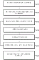
fig. 3A is a flow diagram illustrating a method for establishing a relationship between parameter values of acoustic signals detected from a target region and corresponding focusing characteristics at the target region, in accordance with various embodiments of the present invention;
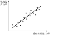
figure 3B illustrates an exemplary relationship between parameter values of an acoustic signal from a target region and corresponding focusing characteristics at the target region, in accordance with various embodiments of the present invention;
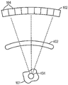
fig. 4A illustrates an embodiment of a 3D skull replica or an ex vivo skull in a focused ultrasound system, according to various embodiments;
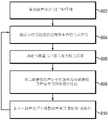
figure 4B is a flow chart illustrating a method of establishing a relationship between parameter values of acoustic signals from a target region and corresponding focusing characteristics at the target region using a 3D skull replica or an ex vivo skull, in accordance with various embodiments of the present invention;
fig. 5 illustrates a plurality of transducer regions and a plurality of acoustic signal detectors for measuring acoustic signals from a target region, in accordance with various embodiments of the present invention;
fig. 6 is a flow diagram illustrating a method for establishing a relationship between spectral features of an acoustic signal from a target region and corresponding focusing characteristics at the target region, according to various embodiments of the invention;
fig. 7 is a flow diagram illustrating a method of measuring and improving the focusing characteristics at the target region in real time during treatment according to various embodiments of the invention;
figure 8 is a flow chart illustrating a method for achieving desired focusing characteristics at a target region without directly measuring the focusing characteristics at the target region, in accordance with various embodiments of the present invention;
figure 9A is a flow diagram illustrating an exemplary method for determining ultrasound application frequency in focused ultrasound therapy in accordance with various embodiments of the invention; and
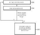
figure 9B is a flow diagram illustrating an exemplary method for enhancing the therapeutic effect of an ultrasound procedure using microbubbles according to various embodiments of the invention.
Detailed Description
Fig. 1 shows an exemplary ultrasound system 100 for generating and delivering a focused beam of acoustic energy to a target region 101 within a patient. The illustrated system 100 includes a phased array 102 of transducer elements 104, a beamformer 106 driving the phased array 102, a controller 108 in communication with the beamformer 106, and a frequency generator 110 providing input electronic signals to the beamformer 106. In various embodiments, the system further includes a detection system 112 for measuring information about the focus at the target region 101 and an administration system 113 for introducing exogenous agents (including, for example, emulsions and/or droplets composed of various liquid perfluorocarbon agents) and/or microbubbles into the patient as described below.
The array 102 may have a curved (e.g., spherical or parabolic) or other contoured shape suitable for placement on the surface of a patient's body, or may include one or more planar or other shaped portions. The dimensions of which may vary from millimetres to tens of centimetres. The transducer elements 104 of the array 102 may be piezo-ceramic elements and may be mounted in silicone rubber or any other material suitable for mechanical coupling between the damping elements 104. Piezoelectric composites, or generally any material capable of converting electrical energy into acoustic energy, may also be used. To ensure maximum power transfer to the transducer element 104, the element 104 may be configured for 50 Ω electrical resonance, matching the input connector impedance.
The transducer array 102 is connected to a beamformer 106, the beamformer 106 driving the individual transducer elements 104 such that they collectively produce a focused ultrasound beam or field. For n transducer elements, the beamformer 106 may contain n driver circuits, each driver circuit comprising or consisting of an amplifier 118 and a phase delay circuit 120; each driving circuit drives one of the transducer elements 104. The beamformer 106 receives a Radio Frequency (RF) input signal, typically in the range of 0.1MHz to 10MHz, from a frequency generator 110, which frequency generator 110 may be, for example, a DS345 type generator available from Stanford Research Systems. For the n amplifiers 118 and delay circuits 120 of the beamformer 106, the input signal may be split into n channels. In some embodiments, the frequency generator 110 is integrated with the beamformer 106. The radio frequency generator 110 and beamformer 106 are configured to drive the individual transducer elements 104 of the transducer array 102 at the same frequency but with different phases and/or different amplitudes.
Amplification or attenuation factor a applied by the beamformer 1061-αnAnd phase shift a1-anFor transmitting and focusing ultrasound energy onto the target region 101 through intervening tissue located between the transducer elements 104 and the target region and causing waveform distortion in the intervening medium. The amplification factor and phase shift are calculated using the controller 108, and the controller 108 may provide the calculation function by software, hardware, firmware, hardwiring, or any combination thereof. In various embodiments, the controller 108 utilizes a general or special purpose digital data processor programmed with software to determine the phase shift and amplification factors needed to obtain the desired focus or any other desired spatial field pattern in a conventional manner and without undue experimentation.
To confirm position and measure characteristics of focus, in various embodiments, the detection system 112 includes or consists of an ARFI imaging system. ARFI is generally preferred because it generally requires lower ultrasound energy during alignment and calibration than other methods, and it is preferable to minimize the ultrasound intensity prior to actual treatment to avoid damaging tissue outside the target. In one embodiment, the ARFI imaging system is magnetic resonance-based (i.e., MR-ARFI). Typically, in MR-ARFI, the ultrasound transducer 102 is driven so as to focus ultrasound waves/pulses at or near the target region 101 in the body. The ultrasonic waves impart acoustic radiation forces on the material along its path. At the focal point where the waves converge, the pressure is highest, causing a temporary local displacement of the material in the longitudinal direction and/or the generation of shear waves propagating radially away from the focal point. Thus, ultrasonic pressure produces a displacement field that corresponds directly to the acoustic field. The displacement field can then be visualized by the MRI device.
Fig. 2 shows an exemplary MRI apparatus 200 comprising a cylindrical electromagnet 204, generating the necessary static magnetic field within a bore 206 of the electromagnet 204. During a medical procedure, a patient is positioned within the aperture 206 on the movable support bracket 208. A target region 210 (e.g., a patient's head) may be positioned within the imaging region 212, where the electromagnet 204 generates a substantially uniform field. A set of cylindrical magnetic field gradient coils 213 may also be disposed within the bore 206 and around the patient. The gradient coil 213 generates magnetic field gradients of a predetermined magnitude in a predetermined time and in three mutually orthogonal directions. With the field gradients, different spatial locations can be associated with different precession frequencies (pressure frequencies), providing the MR images with their spatial resolution. An RF transmitter coil 214 surrounding the imaging region 212 transmits RF pulses into the imaging region 212 and receives MR response signals transmitted from the target region 210. (alternatively, separate MR transmitter and receiver coils may be used.)
The MRI apparatus 200 generally includes an MRI controller 216 that controls the relative timing and strength of the pulse sequences, i.e., the magnetic field gradients and RF excitation pulses, and the response detection periods. The MRI controller 216 may be combined with the transducer controller 108 into an integrated system control facility.
The MR response signals are amplified, conditioned and digitized into raw data using conventional image processing systems and further converted into an image data array by conventional methods known to those of ordinary skill in the art. The image processing system may be part of the MRI controller 216 or may be a separate device (e.g., a general purpose computer containing image processing software) in communication with the MRI controller 216 and/or the transducer controller 108.
In various embodiments, gradient coils 213 apply transient motion or displacement sensitive magnetic field gradients to the imaging region 212 to visualize the displacement field of the material generated by the ultrasonic pressure. When an ultrasound pulse is applied in the presence of such a gradient, the resulting displacement is encoded directly into the phase of the MR response signal. For example, the gradient coils 213 and the transducer 102 may be configured such that the ultrasound pulse pushes the material near the focal point towards a region of the magnetic field having a higher field strength. In response to the resulting magnetic field changes, the phase of the MR response signal changes proportionally, thereby encoding the displacement in the signal caused by the ultrasonic radiation force. Generally, the stronger the acoustic force (acoustic force), the greater the maximum displacement at the center of focus will be. This relationship may be used to adjust the transducer elements to achieve a desired pressure at the focal point, as described further below. More details regarding MR-ARFI are provided in U.S. patent No. 8,932,237 and U.S. patent publication No. 2013/0150756, the entire disclosures of which are incorporated by reference into the present application.
Alternatively or additionally, the detection system 112 may comprise an acoustic signal detector (e.g. a hydrophone) for measuring acoustic signals reflected from the target region 101; the reflected signal may provide information about the target region 101 (e.g., sound pressure or peak intensity). Thus, the acoustic signal detector may indirectly monitor the focus characteristics at the target in real time during treatment. In one embodiment, the transducer elements 104 have both transmit and receive capabilities. Thus, at least some of the transducer elements may be configured to measure acoustic signals from the target region 101. Methods of configuring the transducer elements 104 for detecting reflected signals are provided, for example, in U.S. patent application No. 62/861,282, the contents of which are incorporated herein by reference.
In various embodiments, the acoustic energy emitted by the transducer elements 104 may be above a threshold, causing bubbles or small groups of bubbles (or "microbubbles") to be generated in the liquid contained in the tissue. The microbubbles act as ultrasound reflectors as they encapsulate gas therein. Additionally or alternatively, microbubbles (and/or exogenous agents) may be introduced into the target region 101 via the administration system 113 in order to provide a stronger reflected signal from the target. Depending on the amplitude and frequency of the applied acoustic field, the microbubbles may oscillate, flow, and/or collapse. Thus, in various embodiments, ultrasound parameters (e.g., amplitude and/or frequency associated with the transducer elements) may be adjusted such that the microbubbles create local discontinuities in the medium during cavitation and behave as half-wavelength (or, in some embodiments, quarter-wavelength) rigid spherical reflectors. The amplitude of the signal from an exploding microbubble may be directly related to the local peak acoustic intensity, regardless of the specific microstructure of the cavitation event. Thus, by detecting the amplitude or power of the signal from the microbubble explosions, the focal properties (e.g., acoustic power or peak intensity) at the target region 101 can be acquired or estimated. Methods of generating and/or introducing microbubbles into a target region 101 are provided, for example, in U.S. patent application nos. 15/708,214, 15/837,392, and 62/597,073, international application No. PCT/IB2017/000990, and international patent applications entitled "Controlling Therapeutic Agent in Microbubble-Enhanced Ultrasound Procedures for Controlling Delivery of Therapeutic Agent in Microbubble-Enhanced Ultrasound Procedures" and "Controlling of Exogenous Agent Characteristics in Microbubble-Mediated Ultrasound Procedures" filed on even date herewith, the contents of which are incorporated herein by reference.
In various embodiments, a relationship between a value of a parameter (e.g., power or amplitude) of the detected acoustic signal and one or more focusing characteristics (e.g., acoustic power or peak acoustic intensity) at the target region is established during or before the ultrasound therapy. In one embodiment, the relationship is established based on measurements of previous treatments of the same or different patients, averages across patients, or ex vivo laboratory experiments. Fig. 3A shows an exemplary method 300 whereby an acoustic signal detector (or ultrasound transducer) is used in conjunction with an RFI system for establishing a relationship at the beginning of treatment. In a first step 302, the transducer elements may apply ultrasound pulses/waves to a target region. Parameter values (e.g., amplitude, phase, and/or frequency) associated with the transducer elements may be estimated empirically and/or using physical models to generate focus at the target region as described above. In a second step 304, by applying ultrasound, the acoustic signal detector 112 and the ARFI system may be activated to measure acoustic signals from the target and tissue displacement at the target, respectively, substantially simultaneously. In a third step 306, the measured tissue displacement is then converted into a corresponding acoustic pressure based on a known relationship, which may be established empirically based on a series of measurements or obtained from literature. In a fourth step 308, ultrasound parameters (e.g., amplitude, phase, or frequency) may then be adjusted. The transducer elements may then be activated based on the adjusted parameter values, and the acoustic signal and tissue displacement are measured in response to the adjusted parameter values. In various embodiments, steps 302-308 are repeated until sufficient data has been acquired to reliably establish a relationship between the value of the acoustic signal and the focusing characteristics at the target region 101 (as shown in fig. 3B). The relationship may then be stored in a memory accessible to the controller 108 (in step 310).
Alternatively, referring to fig. 4A and 4B, a patient-specific 3D skull replica (or ex vivo skull) 402 and a second detector apparatus (e.g., hydrophone) 404 disposed at the target region 101 within the printed skull (or ex vivo skull) can be used to establish a relationship between a parameter value (e.g., power or amplitude) of the detected acoustic signal and a focusing characteristic (e.g., acoustic power or peak acoustic intensity) at the target region. In one embodiment, prior to treatment, the MRI apparatus 200 and/or other imaging devices (e.g., Computed Tomography (CT) devices, Positron Emission Tomography (PET) devices, Single Photon Emission Computed Tomography (SPECT) devices, or ultrasound devices) are activated to acquire anatomical features (e.g., type, characteristics, structure, thickness, density, etc.) and/or material features (e.g., energy absorption of tissue at the frequency or speed of sound employed) of the patient's skull (in step 412). A patient-specific 3D skull replica 402 may be created based on the acquired anatomical/material features using, for example, 3D printing (in step 414). The 3D skull replica can then be placed in an environment similar to that used to treat patients; ultrasound may be applied to the target region 101 by traversing the 3D replica of the skull (in step 416). The second detector device 404 disposed at the target region 101 may be activated to measure the focal properties (e.g., acoustic power and/or peak acoustic intensity) produced by the applied ultrasound waves (in step 418). Additionally, the detection system 112 may measure acoustic signals from the target region 101 (in step 420). Again, the ultrasound parameters may be adjusted (in step 422); the transducer is then activated based on the adjusted parameter, and the acoustic signal and the focus characteristic may be measured in response to the adjusted parameter value using the detection system 112 and the second detector device 404, respectively. In one embodiment, step 416-422 is repeated until sufficient data has been acquired to reliably establish a relationship between the value of the acoustic signal and the focusing characteristics at the target region 101 (as shown in FIG. 3B). Again, the relationship may be stored in a memory accessible to the controller 108 (in step 424). Methods of creating patient-specific 3D cranial replica are provided, for example, in U.S. patent application No. 16/132,630, the contents of which are incorporated by reference into the present application.
With the established relationship between the measured values and the one or more focusing characteristics, the focusing characteristics at the target region may be monitored by inferring the focusing characteristics (e.g., acoustic power or peak intensity) at the target region from the measured acoustic signals and/or tissue displacement. Based on the measured acoustic power and/or tissue displacement, the controller 108 may automatically adjust the ultrasound parameters in a closed-loop manner in order to obtain the desired acoustic pressure. For example, if the measured acoustic power is less than a desired value, the controller 108 may increase the ultrasound power and/or adjust the frequency and/or phase shift associated with the transducer elements 104 to increase the acoustic power at the target region. By iterative cycles of measurement and adjustment as ultrasound reflects from the microbubbles, a high power ultrasound focus can be reliably generated at the target region 101.
Additionally or alternatively, referring to fig. 5, the acoustic signals from the target region 101 may be detected by the transducer elements 104 located at different regions 502-508 of the transducer 102 and/or a plurality of acoustic signal detectors 510-516 associated with different regions of the transducer 102. By analyzing the relative amplitudes of the reflected acoustic signals received at different regions of the transducer 102, the relative contribution of energy at the target region 101 from the various regions of the transducer can be determined. The controller 108 may then adjust the ultrasound parameter values based on the determined relative energy contributions in order to improve the focusing characteristics at the target region 101, avoid damage to non-target tissue and/or shape the acoustic beam at the target. For example, if the amplitude of the acoustic signals received at the transducer regions 502, 504 is greater than the amplitude of the acoustic signals received at the transducer regions 506, 508, the transducer regions 502, 504 contribute more energy at the target region 101 than the transducer regions 506, 508 (in other words, more energy from the transducer regions 506, 508 is absorbed/refracted/reflected on the beam path before reaching the target region 101). Accordingly, the controller 108 may increase the energy emitted from the transducer regions 506, 508 to compensate for the energy lost along the beam path to the target 101, thereby increasing the acoustic power at the target region 101. Alternatively, the controller 108 may reduce the energy emitted from the transducer regions 506, 508 to avoid overheating tissue located on the beam path to the target. This may be beneficial when, for example, non-target tissue located in the beam path is a vital organ and/or is highly heat sensitive. In some embodiments, the controller 108 may shape the focus based on acoustic signals received at different transducer regions. For example, the controller 108 may adjust transmit phase and amplitude apodization (amplitude apodization) from the transducer region to shape the focus to conform to a particular target shape. Alternatively or additionally, the controller 108 may shape the focus using a physical model that simulates the acoustic beam from the transducer region to the target 101. Methods for building a physical model and using the physical model to perform acoustic simulations are provided in international patent publication No. WO 2018/130867 and U.S. patent publication No. 2015/0359603, the entire disclosures of which are incorporated by reference in the present application.
In various embodiments, one or more focal characteristics (e.g., acoustic power) at the target region 101 are estimated based on spectral features of the acoustic signals detected from the microbubbles. This is possible because different types of cavitation typically have different spectral characteristics. For example, at relatively low acoustic powers (e.g., 1-2 watts above the microbubble generation threshold), the generated microbubbles are subject to compression and rarefaction oscillations of equal magnitude, so the microbubbles generally remain unbroken (i.e., "steady state cavitation"). The acoustic response of the microbubbles is linear at this low acoustic power, and the frequency of the ultrasound emitted from the microbubbles is the same as or a harmonic of the frequency of the incident ultrasound (i.e., the fundamental or fundamental harmonic frequency). At higher acoustic powers (e.g., above the microbubble generation threshold of 10 watts) the generated microbubbles experience greater rarefaction than compression, which may lead to cavitation and nonlinear acoustic response of the microbubbles. The acoustic signal returned from the cavitation event may include frequencies at the fundamental frequency and/or harmonics, ultraharmonics, and/or subharmonics of the fundamental frequency. Thus, the method may involve mapping between various spectral features and their corresponding acoustic powers causing cavitation events, which in turn may be established directly prior to treatmentAnd (5) standing. As used herein, the term "fundamental" frequency or "fundamental harmonic" frequency f0Refers to the frequency (or time varying frequency) of the ultrasound waves/pulses emitted from the transducer array 102; the term "harmonic" refers to an integer number of fundamental frequencies (e.g., 2 f)0、3f0、4f0Etc.); the term "ultraharmonics" refers to fractional frequencies (e.g., 3 f) between two non-zero integer harmonics0/2、5f0/4, etc.); the term "subharmonic" refers to the fraction (e.g., f) between the fundamental frequency and the first harmonic0/2、f0/3、f0/4, etc.).
Fig. 6 illustrates an exemplary method 600 for establishing a mapping between spectral features and their corresponding acoustic powers in accordance therewith. In a first step 602, microbubbles may be generated within the target region 101 and/or introduced into the target region 101. In a second step 604, the transducer elements 104 may apply ultrasound pulses/waves to the target region. Again, parameter values (e.g., amplitude, phase, or frequency) associated with the transducer elements 104 may be estimated empirically and/or using a physical model as described above in order to generate focus at the target region. In a third step 606, the acoustic signal detector 112 (or, in some embodiments, the transducer elements 104) and the ARFI system may be activated by applying ultrasound waves to measure acoustic signals from the target and tissue displacement at the target substantially simultaneously. In a fourth step 608, the measured acoustic signal is then transmitted to the controller 108 to determine a spectral signature associated therewith. Additionally, the measured tissue displacement may be converted to a corresponding acoustic pressure based on a known relationship as described above. In a fifth step 610, ultrasound parameters (e.g., amplitude, phase, or frequency) may then be adjusted, and acoustic signals and tissue displacement measured in response to the adjusted parameter values. Step 604 as well as step 610 may be repeated until sufficient data has been acquired to reliably establish a relationship between the spectral characteristics of the acoustic signal and one or more focusing characteristics (e.g., acoustic power) at the target region 101. Again, the established relationships may be stored in a memory accessible to the controller 108 (in step 612).
Once the relationship between the parameter values (or, in some embodiments, spectral features) of the acoustic signal and the focusing characteristics at the target region is established using, for example, the methods described in fig. 3B, 4B, and 6, the ultrasound focusing characteristics at the target region 101 may be monitored in real-time during the treatment procedure. In particular, an acoustic signal from the target region 101 is obtained, and based on the acoustic signal, one or more parameters (e.g., phase shift, frequency, and/or amplitude) of the transducer elements 104 are inferred, and may be adjusted in order to improve the focusing characteristics. Fig. 7 illustrates an exemplary method 700 for measuring and improving ultrasound focusing characteristics accordingly. In a first step 702, ultrasound parameter values are estimated empirically and/or using a physical model to produce focus at the target region 101, as described above. In a second step 704, the transducer elements 104 are activated based on the estimated parameter values. In a third step 706, the detection system 112 (e.g., the MR-ARFI imaging system and/or the acoustic signal detector) is employed to measure a response (e.g., tissue displacement and/or acoustic signal) caused by the applied acoustic pressure at the target region 101 during the treatment. Alternatively, acoustic pressure may be measured using microbubbles generated within the target region 101 and/or introduced into the target region 101. In a fourth step 708, based on the response measured in step 706, the acoustic pressure at the target region 101 may be estimated. In one embodiment, this step involves using the relationship established between the value (e.g., power or amplitude) of the detected acoustic signal (and/or detected tissue displacement) and the corresponding focusing characteristic (e.g., acoustic power or peak acoustic intensity) at the target region 101 as described above. Subsequently, transducer parameter values (e.g., phase shift, frequency, and/or amplitude) may be adjusted based on the estimated acoustic power at the target (in step 708). Step 702-708 may be repeated until the detected ARFI signal and/or the acoustic reflection signal correspond to the desired sound pressure.
In another embodiment, it is not necessary to obtain focusing characteristics at the target region in order to obtain the desired power at the target region 101. For example, referring to fig. 8, treatment efficiency can be optimized by finding the maximum intensity (or amplitude) of the reflected ultrasound waves, since a higher reflected intensity represents a higher beam intensity at the focal point. Thus, the transducer elements 104 may first apply ultrasonic pulses/waves to the target region 101 (in step 802). The acoustic signal detector 112 and/or the transducer element 104 may then be used to detect acoustic reflection signals from the target 101 (in step 804). In some embodiments, the measured acoustic signal is transmitted to the controller 108, determining the intensity associated therewith (in step 806). The controller 108 may compare the intensity of the currently received reflection to the intensity of the previously received reflection (if any) (in step 808) and, based on the difference, the controller may adjust the amplitude and/or phase of the ultrasound beam in the next ultrasound processing (in step 810). Again, steps 802-810 may be iterative (i.e. determining initial parameter values for the transducer elements for the next sonication based on previous measurements) until the intensity of the reflected sound beam reaches a maximum value. In some embodiments, the iterative process stops when the difference between the currently measured intensity and the previously measured intensity is below a threshold and/or the number of iterations exceeds a predetermined limit. The threshold value may be determined, for example, to be lower than a value at which no clinical effect is observed.
The goal of focused ultrasound lesion therapy is generally to maximize the energy absorbed at the target while minimizing exposure to ultrasound to healthy tissue surrounding the target and to tissue along the path between the transducer and the target. The degree of ultrasound absorption for the length of propagation in tissue is a function of frequency and is given by:
I=l0 e-2α/Z
where I denotes the sound intensity at the target region 101, I0Denotes the initial intensity of an ultrasonic beam emitted from the transducer element, f denotes the frequency of the ultrasound (in MHz), α denotes the pressure absorption coefficient (in cm) in the relevant frequency range-1·MHz-1In units) and can be acquired from known literature, z represents the distance (in cm) that an ultrasound beam propagates through tissue before reaching the target region. The larger the product α · f, the greater the energy absorption in the target region. Thus, in some embodiments, the frequency of the ultrasound is optimized by sequentially sonicating the target region 101 with waves having different "test frequencies" over a range of test frequencies; for each tested frequency, energy absorption in the target region 101 is measured using, for example, an ARFI systemThe received acoustic power. Additionally or alternatively, ultrasound at the test frequency is transmitted to the microbubbles at the target region; the acoustic signal reflected therefrom can be analyzed to obtain the acoustic intensity I at the target. The energy absorption at the target can then be inferred from the product I · α · f. The test range may span the entire frequency range suitable for ultrasound therapy (e.g., 0.1MHz to 10MHz in various embodiments), but is typically a much smaller sub-range thereof, within which the optimal frequency is expected. Such sub-ranges may be determined, for example, based on physical models that estimate optimal frequencies, results of simulations, or empirical data obtained for the same target of other patients. The frequencies to be tested may be evenly or unevenly distributed over the test range. In various embodiments, the density of the test frequencies increases as the estimated optimal frequency is approached based on, for example, previous experience with the same organ or tissue. The test range and test frequency can be predetermined or dynamically adjusted during the optimization process. For example, in one embodiment, testing is first performed over a large testing range (e.g., from 0.1 to 1MHz) at large frequency intervals (e.g., in steps of 20 kHz) to determine sub-ranges of frequencies that produce high energy absorption at the target region 101, and then, by testing at smaller intervals (e.g., in steps of 5 kHz), the optimal frequency is determined within the determined sub-ranges. In another embodiment, the test is performed on a predetermined subset of possible test frequencies, each actual test frequency being selected from a set of possible test frequencies based on the results of a previous test or simulation.
Thus, optimizing the ultrasound frequency may involve iteratively setting the test frequency, sonicating the target region 101 at a selected frequency, and quantitatively evaluating the generated acoustic power at the target region 101. Since the sound intensity I is a function of the sound pressure P (I ═ P)2Z, where Z represents acoustic impedance), the frequency dependent absorption coefficient of the target tissue can be calculated based on the test frequency and its resulting acoustic pressure. In one embodiment, the frequency with the highest product I · α · f is selected as the optimal frequency to maximize the amount of energy absorbed at the target region. In another embodiment, the test frequency corresponding to the maximum sound pressure is determined as the optimum frequency. In any case, during treatment, the ultrasound transducer 102 is activated to treat the target according to the determined optimal frequency. Although the description herein refers only to assessing acoustic power at the target region for ease of reference, it should be understood that any suitable experimental technique for measuring parameters related to energy absorption at the target region 101 in a known and predictable manner may be used and fall within the scope of the present invention. For example, MRI thermometry may be employed to measure the temperature increase in the target region 101 generated by the absorbed energy. Further details regarding determining an optimal frequency for ultrasound applications are provided, for example, in U.S. patent publication No. 2016/0008633, the contents of which are incorporated by reference into this application.
While the optimum frequency may maximize the amount of energy absorbed at the target, it may also maximize the exposure of healthy tissue surrounding the target to ultrasound, causing undesirable damage thereto. Thus, in some embodiments, it is preferable to apply sonication with a frequency (compared to the optimal frequency) corresponding to the lower product I · α · f to avoid damaging non-target tissue. However, this may significantly reduce the amount of energy available at the target region 101. Thus, in some embodiments, when the energy absorbed by the target is below a predetermined value corresponding to a minimum acceptable treatment efficiency, microbubbles are introduced and/or generated at the target region 101 to increase the treatment efficiency through interaction between the microbubbles and the acoustic beam. Again, the amount of energy absorption at the target may be inferred from acoustic power or other energy-related parameters measured using ARFI, acoustic signals reflected or transmitted from the target 101, and/or other suitable methods. In addition, after administration of the microvesicles to increase the efficiency of the treatment, information characterizing energy absorption at the target may be updated, and based thereon, the administration profile (e.g., concentration, administration dose, rate, or time) of the microvesicles may be adjusted.
Fig. 9A illustrates an exemplary method 900 for determining ultrasound application frequencies in focused ultrasound therapy therefrom. In a first step 902, information (e.g., anatomical properties) about target and/or non-target tissue is obtained using an imaging device (e.g., MRI apparatus 200). Based on the acquired information, a tissue model characterizing material properties of the target and/or non-target tissue may be created (in a second step 904). For example, a method of creating an organization model is described in international application No. PCT/IB2017/001689 (filed 12/13/2017), the entire disclosure of which is incorporated herein by reference. In a third step 906, the optimum frequency to maximize the energy absorbed at the target 101 can be determined using the methods described above. In a fourth step 908, the influence of ultrasound energy on non-target tissue and the risk of damage thereto is estimated based on the tissue model and the determined optimal frequency. If the non-target tissue has high thermal resistance and/or can withstand damage without adverse clinical effects (or if the risk of damaging the tissue is low, e.g., less than 20%), the transducer can be activated for treatment (in step 910) at the optimal frequency determined in step 806. However, if the non-target organ is heat sensitive and/or the risk of damaging it is high (e.g., greater than 50%), the ultrasound application frequency is adjusted to obtain a lower product I · α · f (compared to the optimal frequency) to avoid damaging the non-target tissue (in step 912). The transducer 102 may then be activated based on the adjusted frequency to begin the therapy program (step 910).
Referring to fig. 9B, during treatment, the amount of energy absorption at the target 101 is inferred (in step 914) from the acoustic power or other energy-related parameter measured using ARFI, acoustic signals reflected or transmitted from the target 101, and/or other suitable methods as described above. If the energy absorbed at the target 101 is below a predetermined value corresponding to a minimum acceptable therapeutic efficiency, microbubbles may be introduced and/or generated at the target region 101 as described above for enhancing the ultrasound therapy effect (in step 916). Energy absorption at the target can be continuously monitored and updated, and based thereon, the dosing profile (e.g., concentration, dose administered, rate, or time) of the microbubbles can be adjusted to improve the focusing characteristics (in step 818).
Accordingly, various embodiments of the present invention advantageously utilize the detection system 112 to provide closed loop feedback information (e.g., acoustic power) about the target to the operator or automatic controller 108 to allow adjustment of the ultrasound parameters (or in some embodiments the introduction of microbubbles) to achieve the desired acoustic power or energy absorption at the target in real time during treatment.
Although the examples herein describe the technique with respect to the delivery of ultrasound energy, it should be understood that ultrasound procedures may be performed in conjunction with other therapeutic methods (e.g., radiation therapy or targeted drug delivery). For example, ultrasound-induced microbubble oscillation/cavitation can destroy vascular tissue in the target region 101; this makes the tissue sensitive to radiation, thus reducing the radiation dose required for radiation therapy, while still achieving the desired therapeutic efficacy. In another treatment regime, ultrasound-induced microbubble oscillation/cavitation can increase tissue permeability at the target region (e.g., open the BBB); this allows higher doses of the therapeutic agent to reach the target tissue, thereby enhancing the therapeutic effect while minimizing systemic toxicity. Methods for reducing radiation dose in radiotherapy and increasing tissue permeability at target region 101 using microbubble oscillation/cavitation are provided, for example, in U.S. patent application No. 15/637,163 (filed 2017 on 29), and international application No. PCT/IB2018/000811 (filed 2018 on 29), respectively, the contents of which are incorporated by reference herein.
In addition to or instead of measurements of transmissions from the entire transducer 102, in some embodiments, the above-described methods may be applied to measurements of transmissions from one or more subsets of transducer elements 104. In one embodiment, for the target 101, the transmissions from several subsets of elements having different spatial arrangements are measured separately; the information obtained by analyzing the measurements as described above is used to adjust the transmit power of the subset elements relative to each other. In some embodiments, the frequency and/or power of the subset elements may be adjusted to minimize thermal effects on non-target tissue.
It should be noted that although the ultrasound focusing procedure described herein utilizes microbubbles to reflect ultrasound waves, other methods may be used to reflect ultrasound waves. For example, the administration system 113 can administer emulsions and/or droplets composed of various liquid perfluorocarbon agents into the target region 101 before and/or during treatment. The initial application of the ultrasonic pulse may cause the droplet to evaporate into a microbubble, while the subsequent application of the ultrasonic pulse may reflect from the microbubble. As described above, reflections from the target region 101 may be detected and analyzed.
Generally, functions for measuring and improving the focusing characteristics at the target region 101 in real time during ultrasound therapy include, for example, estimating ultrasound parameter values to produce focus at the target region, causing the transducer elements 104 to transmit ultrasound pulses/waves to the target region based on the estimated parameter values, activating an acoustic signal detector and/or ARFI system to measure acoustic signals reflected from the target and tissue displacement at the target, respectively, determining spectral characteristics and/or intensities associated with the measured acoustic reflection signals, converting the measured tissue displacement into corresponding acoustic pressures, comparing the intensity of a currently received acoustic signal to the intensity of a previously received acoustic signal, adjusting the ultrasound parameter values, analyzing imaging data of the target and/or non-target region acquired using one or more imaging modalities (e.g., ultrasound imaging, MR imaging, or a camera), determining the target location, creating a tissue model characterizing material characteristics of the target/non-target region based on the imaging data, determining an optimal frequency that maximizes the amount of energy absorbed at the target 101, estimating the impact of ultrasound energy on and the risk of damage to non-target tissue, creating a copy of the patient-specific 3D skull based on the acquired anatomical/material characteristics, generating and/or introducing microbubbles into the target region within the target region, and/or adjusting an administration profile (e.g., concentration, administration dose, rate, or time) of the microbubbles, as described above, whether integrated in a controller of the ultrasound system 100 and/or the MRI apparatus 200, or provided by a separate external controller or other computing entity or entities, may be configured in one or more modules implemented in hardware, software, or a combination of both. The ultrasound controller 108 and/or the MR controller 216 may include one or more modules implemented in hardware, software, or a combination of both. For embodiments in which functionality is provided as one or more software programs, the programs may be written in any of a number of high-level languages, such as PYTHON, FORTRAN, PASCAL, JAVA, C + +, C #, BASIC, various scripting languages, and/or HTML. Additionally, the software may be implemented in assembly language directed to a microprocessor residing on the target computer; for example, if the software is configured to run on an IBM PC or PC clone, it may be implemented in Intel 80x86 assembly language. The software may be embodied on an article of manufacture including, but not limited to, a floppy disk, a flash disk, a hard disk, an optical disk, magnetic tape, a PROM, an EPROM, an EEPROM, a field programmable gate array or a CD-ROM. Embodiments using hardware circuitry may be implemented using, for example, one or more FPGA, CPLD, or ASIC processors.
In addition, the term "controller" or "automation controller" as used herein broadly includes all necessary hardware components and/or software modules for performing any of the functions described above; the controller may include multiple hardware components and/or software modules, and functionality may be spread between different components and/or modules.
The terms and expressions which have been employed herein are used as terms of description and not of limitation, and there is no intention, in the use of such terms and expressions, of excluding any equivalents of the features shown and described or portions thereof. Additionally, having described certain embodiments of the invention, it will be apparent to those of ordinary skill in the art that other embodiments incorporating the concepts disclosed herein may be used without departing from the spirit and scope of the invention. The described embodiments are, therefore, to be considered in all respects only as illustrative and not restrictive.
The claims are as follows:
Claims (23)
1. a system for focusing an ultrasound transducer, comprising:
an ultrasound transducer comprising a plurality of transducer elements;
an acoustic signal detector for indirectly measuring a focal property at a target region including nearby exogenous agents or microbubbles; and
a controller configured to:
(a) causing an ultrasound transducer to transmit ultrasound waves to a target region;
(b) causing an acoustic signal detector to indirectly measure a focus characteristic by measuring an acoustic signal from an exogenous agent or microbubble, wherein the focus characteristic comprises at least one of a sound pressure or a peak sound intensity; and
(c) a parameter value associated with at least one of the transducer elements is adjusted based at least in part on the indirectly measured focal characteristic to achieve a target therapeutic power at the target region.
2. The system of claim 1, wherein the acoustic signal detector is further configured to measure at least one of an acoustic pressure or a peak acoustic intensity at a non-target region, and the controller is further configured to adjust a parameter value associated with at least one of the transducer elements so as to avoid damage to non-target tissue.
3. The system of claim 1, further comprising an applicator for introducing exogenous agents or microbubbles to the target region.
4. The system of claim 1, wherein the controller is further configured to cause the acoustic signal detector to measure acoustic signals from the exogenous agent or microbubbles.
5. The system of claim 4, wherein the controller is further configured to determine the focal characteristic based at least in part on a value associated with the measured acoustic signal.
6. The system of claim 5, wherein the controller is further configured to:
establishing a relationship between a value associated with the measured acoustic signal and the focus characteristic; and
determining a focus characteristic based at least in part on the relationship.
7. The system of claim 5, wherein the values associated with the measured acoustic signals include at least one of amplitude, power, wave pattern, or spectral signature.
8. The system of claim 3, wherein the controller is further configured to adjust the parameter values to (i) cause cavitation of the microbubbles, and (ii) cause the microbubbles to act as half-wavelength or quarter-wavelength rigid spherical reflectors during cavitation.
9. The system of claim 3, wherein the controller is further configured to cause at least some of the transducer elements to measure acoustic signals from the exogenous agent or microbubbles.
10. The system of claim 1, wherein the controller is further configured to:
comparing the measured treatment power associated with the indirectly measured focus characteristic to a predetermined value; and is
The applicator is caused to introduce the exogenous agent or microbubbles to the target region by determining that the measured therapeutic power is less than a predetermined value.
11. The system of claim 1, wherein the parameter value comprises at least one of a frequency, a phase, a power level, or an amplitude of a signal driving at least one of the transducer elements.
12. The system of claim 11, wherein the acoustic signal detector indirectly measures the focal properties at two or more regions of the transducer elements, the controller further configured to adjust the parameter value based at least in part on the measurements at the two or more regions of the transducer elements.
13. The system of claim 12, wherein:
the acoustic signal detectors comprise two or more acoustic signal detectors for measuring the intensity of the acoustic signal from the target area at two or more regions of the transducer element, and
the controller is further configured to adjust power levels associated with two or more regions of the transducer element based at least in part on the measured intensity of the acoustic signal.
14. The system of claim 13, wherein the controller is further configured to adjust power levels associated with two or more regions of transducer elements so as to compensate for differences between the intensities of the acoustic signals measured at the two or more regions of transducer elements.
15. The system of claim 12, wherein the controller is further configured to adjust a parameter value associated with at least one of the transducer elements based on acoustic simulation.
16. The system of claim 15, wherein the controller is further configured to adjust a parameter value associated with at least one of the transducer elements in order to shape the acoustic beam at the target region.
17. The system of claim 11, wherein the controller is further configured to determine energy absorption of tissue at the target region based at least in part on the indirectly measured focal properties.
18. The system of claim 17, wherein the controller is further configured to determine a frequency based at least in part on the energy absorption.
19. The system of claim 1, wherein the controller is further configured to:
(d) transmitting a second ultrasonic wave to the target region based on the adjusted parameter value; and
(e) repeating the steps (b), (c) and (d) until the stop condition is met.
20. The system of claim 19, wherein the stop condition is one or more of:
a difference between a currently measured focus characteristic and a previously measured focus characteristic is below a threshold; or
The number of iterations exceeds a predetermined limit.
21. A system for focusing an ultrasound transducer, comprising:
an ultrasound transducer comprising a plurality of subsets of transducer elements, each subset having a different spatial arrangement relative to a target region;
an acoustic signal detector for measuring a focal property at a target region including nearby exogenous agents or microbubbles; and
a controller configured to:
(a) causing two or more subsets of transducer elements to transmit ultrasound waves to a target region;
(b) causing an acoustic signal detector to indirectly measure a focus characteristic by measuring an acoustic signal from an exogenous agent or microbubble, wherein the focus characteristic comprises at least one of a sound pressure or a peak sound intensity; and
(c) based at least in part on the indirectly measured focus characteristics, a parameter value associated with at least one of the subset of transducer elements is adjusted to achieve a target therapeutic power at the target region.
22. The system of claim 21, wherein the parameter value comprises a transmit power.
23. The system of claim 21, wherein the acoustic signal detector is further configured to measure at least one of an acoustic pressure or a peak acoustic intensity at a non-target region, and the controller is further configured to adjust a frequency or transmit power associated with at least one of the subset of transducer elements to avoid damaging non-target tissue.
Applications Claiming Priority (7)
| Application Number | Priority Date | Filing Date | Title |
|---|---|---|---|
| US201762597076P | 2017-12-11 | 2017-12-11 | |
| US201762597071P | 2017-12-11 | 2017-12-11 | |
| US201762597073P | 2017-12-11 | 2017-12-11 | |
| US62/597,073 | 2017-12-11 | ||
| US62/597,071 | 2017-12-11 | ||
| US62/597,076 | 2017-12-11 | ||
| PCT/IB2018/001603 WO2019116107A1 (en) | 2017-12-11 | 2018-12-05 | Adaptive, closed- loop ultrasound therapy |
Publications (2)
| Publication Number | Publication Date |
|---|---|
| CN111712301A CN111712301A (en) | 2020-09-25 |
| CN111712301B true CN111712301B (en) | 2022-07-22 |
Family
ID=65276216
Family Applications (5)
| Application Number | Title | Priority Date | Filing Date |
|---|---|---|---|
| CN201880089076.2A Active CN111712301B (en) | 2017-12-11 | 2018-12-05 | Adaptive closed-loop ultrasound therapy |
| CN201880087835.1A Active CN111655337B (en) | 2017-12-11 | 2018-12-05 | Controlling delivery of therapeutic agents in microbubble enhanced ultrasound procedures |
| CN202310668437.1A Pending CN116617589A (en) | 2017-12-11 | 2018-12-05 | Controlling delivery of therapeutic agents in microbubble enhanced ultrasound procedures |
| CN202211472933.1A Pending CN115779287A (en) | 2017-12-11 | 2018-12-11 | System for microbubble enhanced target tissue treatment |
| CN201880088970.8A Active CN111699022B (en) | 2017-12-11 | 2018-12-11 | System for microbubble enhanced target tissue treatment |
Family Applications After (4)
| Application Number | Title | Priority Date | Filing Date |
|---|---|---|---|
| CN201880087835.1A Active CN111655337B (en) | 2017-12-11 | 2018-12-05 | Controlling delivery of therapeutic agents in microbubble enhanced ultrasound procedures |
| CN202310668437.1A Pending CN116617589A (en) | 2017-12-11 | 2018-12-05 | Controlling delivery of therapeutic agents in microbubble enhanced ultrasound procedures |
| CN202211472933.1A Pending CN115779287A (en) | 2017-12-11 | 2018-12-11 | System for microbubble enhanced target tissue treatment |
| CN201880088970.8A Active CN111699022B (en) | 2017-12-11 | 2018-12-11 | System for microbubble enhanced target tissue treatment |
Country Status (5)
| Country | Link |
|---|---|
| US (3) | US20210187331A1 (en) |
| EP (3) | EP3723857A1 (en) |
| JP (3) | JP7359765B2 (en) |
| CN (5) | CN111712301B (en) |
| WO (3) | WO2019116107A1 (en) |
Families Citing this family (16)
| Publication number | Priority date | Publication date | Assignee | Title |
|---|---|---|---|---|
| US11179581B2 (en) | 2015-03-09 | 2021-11-23 | The Research Foundation For The State University Of New York | Systems and methods for promoting cellular activities for tissue maintenance, repair, and regeneration |
| US11123575B2 (en) | 2017-06-29 | 2021-09-21 | Insightec, Ltd. | 3D conformal radiation therapy with reduced tissue stress and improved positional tolerance |
| JP2022510654A (en) | 2018-11-28 | 2022-01-27 | ヒストソニックス,インコーポレーテッド | Tissue disruption system and method |
| EP3979942A1 (en) * | 2019-06-06 | 2022-04-13 | Insightec Ltd. | Improved magnetic resonance (mr) performance in mr-guided ultrasound systems |
| WO2021014221A1 (en) | 2019-07-25 | 2021-01-28 | Insightec, Ltd. | Aberration corrections for dynamically changing media during ultrasound therapy |
| CN114746148A (en) | 2019-10-11 | 2022-07-12 | 医视特有限公司 | Pre-treatment tissue sensitization for focused ultrasound procedures |
| CN115135381A (en) | 2019-12-18 | 2022-09-30 | 医视特有限公司 | Adaptive single bubble based autofocus and power adjustment in ultrasound procedures |
| AU2021213168A1 (en) | 2020-01-28 | 2022-09-01 | The Regents Of The University Of Michigan | Systems and methods for histotripsy immunosensitization |
| JP2023517858A (en) | 2020-03-05 | 2023-04-27 | インサイテック・リミテッド | Differential Prediction of Aberration Correction for Ultrasound Therapy |
| AU2021282379A1 (en) * | 2020-05-27 | 2023-02-02 | Attune Neurosciences, Inc. | Ultrasound systems and associated devices and methods for modulating brain activity |
| CN113198117B (en) * | 2020-08-18 | 2023-12-22 | 于波 | Combination of chlorin derivatives and ultrasound medical systems |
| CN113040814B (en) * | 2021-03-11 | 2023-12-22 | 飞依诺科技股份有限公司 | Imaging processing method and imaging processing system of ultrasonic microbubble cavitation equipment |
| WO2023275617A2 (en) | 2021-07-01 | 2023-01-05 | Insightec, Ltd. | Diagnostic and treatment monitoring based on blood-brain barrier disruption |
| WO2023084307A1 (en) | 2021-11-12 | 2023-05-19 | Insightec, Ltd. | Ultrasound autofocusing for short-pulse procedures |
| WO2023105288A1 (en) * | 2021-12-09 | 2023-06-15 | Insightec, Ltd. | Systems and methods for effective delivery of monoclonal antibodies to neurological targets |
| WO2024047580A1 (en) * | 2022-08-31 | 2024-03-07 | Insightec Ltd. | Enforced tissue residency of payload molecules by acoustic disruption |
Citations (3)
| Publication number | Priority date | Publication date | Assignee | Title |
|---|---|---|---|---|
| US6740039B1 (en) * | 1999-08-20 | 2004-05-25 | Koninklijke Philips Electronics N.V. | Methods and apparatus for displaying information relating to delivery and activation of a therapeutic agent using ultrasound energy |
| WO2014135987A2 (en) * | 2013-03-06 | 2014-09-12 | Insightec, Ltd. | Frequency optimization in ultrasound treatment |
| WO2017066442A1 (en) * | 2015-10-15 | 2017-04-20 | Insightec, Ltd. | Systems and methods for avoiding mri-originated interference with concurrently used rf systems |
Family Cites Families (44)
| Publication number | Priority date | Publication date | Assignee | Title |
|---|---|---|---|---|
| US6716168B2 (en) * | 2002-04-30 | 2004-04-06 | Siemens Medical Solutions Usa, Inc. | Ultrasound drug delivery enhancement and imaging systems and methods |
| JP2004275850A (en) * | 2003-03-14 | 2004-10-07 | Hitachi Ltd | Ultrasonic device |
| WO2007026300A1 (en) * | 2005-08-30 | 2007-03-08 | Koninklijke Philips Electronics, N.V. | Combination imaging and therapy transducer with therapy transducer amplifier |
| JP5094723B2 (en) * | 2005-08-30 | 2012-12-12 | コーニンクレッカ フィリップス エレクトロニクス エヌ ヴィ | Method of using combined imaging and therapy transducers to dissolve clots |
| WO2007026298A2 (en) * | 2005-08-30 | 2007-03-08 | Koninklijke Philips Electronics, N.V. | Combination imaging and therapy transducer |
| US8257338B2 (en) * | 2006-10-27 | 2012-09-04 | Artenga, Inc. | Medical microbubble generation |
| CN100551440C (en) * | 2006-08-30 | 2009-10-21 | 中国人民解放军第三军医大学第二附属医院 | A kind of therapeutic type ultrasonic microbubble that is used for tumour ultrasonic therapy and preparation method thereof |
| US7974682B2 (en) * | 2006-11-22 | 2011-07-05 | Marcela Gonzalez Molezzi | System and method to adaptively control contrast-enhanced diagnostic imaging procedure |
| US8357112B2 (en) * | 2007-03-09 | 2013-01-22 | Koninklijke Philips Electronics N.V. | Method of controlling a release of a material carried by ultrasound sensitive particles |
| JP4279328B2 (en) * | 2007-05-07 | 2009-06-17 | 株式会社日立製作所 | Ultrasound imaging system |
| US20080299177A1 (en) * | 2007-06-06 | 2008-12-04 | Biovaluation & Analysis, Inc. | Supramolecular Complexes for Use in Acoustically Mediated Intracellular Drug Delivery in vivo |
| WO2009081339A1 (en) * | 2007-12-21 | 2009-07-02 | Koninklijke Philips Electronics, N.V. | Systems and methods for tracking and guiding high intensity focused ultrasound beams |
| CN101244028A (en) * | 2008-02-05 | 2008-08-20 | 许川山 | System for positioning delivery of medicament and quantitatively controlling and releasing |
| US20090234231A1 (en) | 2008-03-13 | 2009-09-17 | Knight Jon M | Imaging Catheter With Integrated Contrast Agent Injector |
| US8425424B2 (en) * | 2008-11-19 | 2013-04-23 | Inightee Ltd. | Closed-loop clot lysis |
| US20110293530A1 (en) * | 2008-11-26 | 2011-12-01 | Arizonia Board Of Regents | Methods and Compositions for Using Bleomycin-Derivatized Microbubbles |
| US8882672B2 (en) | 2008-12-29 | 2014-11-11 | Perseus-Biomed Inc. | Method and system for tissue imaging and analysis |
| US10058837B2 (en) * | 2009-08-28 | 2018-08-28 | The Trustees Of Columbia University In The City Of New York | Systems, methods, and devices for production of gas-filled microbubbles |
| CN101642607B (en) * | 2009-09-01 | 2012-11-28 | 西安交通大学 | Low-strength focusing ultrasonic medicine release controlling and monitoring device based on array energy transducer |
| EP2477550A4 (en) * | 2009-09-15 | 2013-12-04 | Univ Columbia | Systems, methods, and devices for microbubbles |
| US8932237B2 (en) | 2010-04-28 | 2015-01-13 | Insightec, Ltd. | Efficient ultrasound focusing |
| KR101875203B1 (en) * | 2010-06-09 | 2018-07-06 | 리전츠 오브 더 유니버스티 오브 미네소타 | Dual mode ultrasound transducer (dmut) system and method for controlling delivery of ultrasound therapy |
| JP2012213475A (en) | 2011-03-31 | 2012-11-08 | Panasonic Corp | Ultrasonic contrast medium infusion set |
| US9643000B2 (en) * | 2011-09-28 | 2017-05-09 | Koninklijke Philips N.V. | Automated ultrasound mediated delivery |
| CN103842020B (en) | 2011-10-05 | 2016-12-28 | 皇家飞利浦有限公司 | Chemical examination for the delivery of ultrasonic mediation |
| US10449395B2 (en) * | 2011-12-12 | 2019-10-22 | Insightec, Ltd. | Rib identification for transcostal focused ultrasound surgery |
| WO2013166504A2 (en) * | 2012-05-04 | 2013-11-07 | University Of Houston | Targeted delivery of active agents using thermally stimulated large increase of perfusion by high intensity focused ultrasound |
| NL2008816C2 (en) | 2012-05-14 | 2013-11-18 | Univ Twente | Method for size-sorting microbubbles and apparatus for the same. |
| US20150196638A1 (en) * | 2012-07-08 | 2015-07-16 | Sunnybrook Health Sciences Centre | System and method for using ultrasound-stimulated microbubble exposures to induce ceramide accumulation in endothelial and tumor cells |
| CN103654842A (en) * | 2012-09-19 | 2014-03-26 | 重庆融海超声医学工程研究中心有限公司 | Ultrasound monitoring and targeted controlled release system |
| JP6496662B2 (en) * | 2012-10-12 | 2019-04-03 | プロファウンド メディカル インク | Multi-focus ultrasound irradiation for hyperthermia treatment using magnetic resonance guided focused ultrasound |
| US10751125B2 (en) | 2013-01-29 | 2020-08-25 | Insightec, Ltd. | Simulation-based focused-ultrasound treatment planning |
| KR20140103769A (en) * | 2013-02-19 | 2014-08-27 | 삼성전자주식회사 | Method for transmitting ultrasound and ultrasound apparatus by using the same |
| CN103230648B (en) * | 2013-04-24 | 2016-09-14 | 重庆医科大学 | Low-strength focusing ultrasonic molecular imaging and treatment system |
| CN103267800B (en) * | 2013-05-03 | 2015-08-05 | 西安交通大学 | The ultrasonic fast imaging of cavitation microvesicle high s/n ratio and dynamic dimension distribution estimation method |
| EP3046607A4 (en) * | 2013-11-26 | 2017-06-07 | Bayer Healthcare LLC | System and method for medical fluid identification and verification |
| US9949722B2 (en) * | 2013-12-03 | 2018-04-24 | University Of Virginia Patent Foundation | System and method for binding dynamics of targeted microbubbles |
| FR3025112A1 (en) * | 2014-09-02 | 2016-03-04 | Univ Bordeaux | METHOD FOR CONTROLLING TARGET AREA OF HEART, METHOD FOR ABLATION OF TARGET AREA OF HEART, ASSOCIATED SYSTEMS |
| CN105214742B (en) * | 2015-10-10 | 2017-10-31 | 中国科学院深圳先进技术研究院 | The method of microfluid system and manipulation particulate based on artificial structure's sound field |
| GB201601053D0 (en) | 2016-01-20 | 2016-03-02 | Isis Innovation | Method and apparatus for generating bubbles |
| KR101859571B1 (en) * | 2016-07-27 | 2018-05-21 | 주식회사 루트로닉 | An ophthalmic treatment apparatus and method for controlling that |
| US20190151239A1 (en) * | 2016-07-28 | 2019-05-23 | Cerebral Therapeutics LLC | Infusing drug solution directly into brain fluid |
| US11103731B2 (en) | 2017-01-12 | 2021-08-31 | Insightec, Ltd. | Overcoming acoustic field and skull non-uniformities |
| US10575816B2 (en) * | 2017-01-25 | 2020-03-03 | Insightec, Ltd. | Cavitation localization |
-
2018
- 2018-12-05 JP JP2020531574A patent/JP7359765B2/en active Active
- 2018-12-05 CN CN201880089076.2A patent/CN111712301B/en active Active
- 2018-12-05 EP EP18852736.0A patent/EP3723857A1/en active Pending
- 2018-12-05 JP JP2020531576A patent/JP2021505290A/en active Pending
- 2018-12-05 EP EP18842722.3A patent/EP3723855B1/en active Active
- 2018-12-05 US US16/771,771 patent/US20210187331A1/en active Pending
- 2018-12-05 CN CN201880087835.1A patent/CN111655337B/en active Active
- 2018-12-05 US US16/771,768 patent/US11806496B2/en active Active
- 2018-12-05 WO PCT/IB2018/001603 patent/WO2019116107A1/en unknown
- 2018-12-05 WO PCT/IB2018/001537 patent/WO2019116095A1/en unknown
- 2018-12-05 CN CN202310668437.1A patent/CN116617589A/en active Pending
- 2018-12-11 US US16/771,770 patent/US20200391019A1/en active Pending
- 2018-12-11 CN CN202211472933.1A patent/CN115779287A/en active Pending
- 2018-12-11 JP JP2020531629A patent/JP2021505295A/en active Pending
- 2018-12-11 WO PCT/IB2018/001548 patent/WO2019116097A1/en unknown
- 2018-12-11 CN CN201880088970.8A patent/CN111699022B/en active Active
- 2018-12-11 EP EP18845443.3A patent/EP3723856A1/en active Pending
Patent Citations (3)
| Publication number | Priority date | Publication date | Assignee | Title |
|---|---|---|---|---|
| US6740039B1 (en) * | 1999-08-20 | 2004-05-25 | Koninklijke Philips Electronics N.V. | Methods and apparatus for displaying information relating to delivery and activation of a therapeutic agent using ultrasound energy |
| WO2014135987A2 (en) * | 2013-03-06 | 2014-09-12 | Insightec, Ltd. | Frequency optimization in ultrasound treatment |
| WO2017066442A1 (en) * | 2015-10-15 | 2017-04-20 | Insightec, Ltd. | Systems and methods for avoiding mri-originated interference with concurrently used rf systems |
Also Published As
| Publication number | Publication date |
|---|---|
| US20210187331A1 (en) | 2021-06-24 |
| CN111655337A (en) | 2020-09-11 |
| CN115779287A (en) | 2023-03-14 |
| EP3723856A1 (en) | 2020-10-21 |
| WO2019116095A1 (en) | 2019-06-20 |
| EP3723857A1 (en) | 2020-10-21 |
| CN111655337B (en) | 2023-06-27 |
| CN111712301A (en) | 2020-09-25 |
| JP2021505295A (en) | 2021-02-18 |
| EP3723855B1 (en) | 2022-09-07 |
| JP2021505290A (en) | 2021-02-18 |
| WO2019116097A1 (en) | 2019-06-20 |
| CN116617589A (en) | 2023-08-22 |
| WO2019116107A1 (en) | 2019-06-20 |
| US20200391019A1 (en) | 2020-12-17 |
| JP7359765B2 (en) | 2023-10-11 |
| CN111699022B (en) | 2022-12-06 |
| EP3723855A1 (en) | 2020-10-21 |
| CN111699022A (en) | 2020-09-22 |
| US11806496B2 (en) | 2023-11-07 |
| JP2021505289A (en) | 2021-02-18 |
| US20210170204A1 (en) | 2021-06-10 |
Similar Documents
| Publication | Publication Date | Title |
|---|---|---|
| CN111712301B (en) | Adaptive closed-loop ultrasound therapy | |
| JP6934933B2 (en) | Ultrasonic autofocusing with reflection | |
| US11291866B2 (en) | Ultrasound focusing in dynamically changing media | |
| JP7232204B2 (en) | Optimization of ultrasound frequency and microbubble size in microbubble-enhanced ultrasound procedures | |
| CN112236195B (en) | Focused ultrasound system with optimized cavitation monitoring | |
| CN109689160B (en) | Therapeutic ultrasound with reduced interference from microbubbles | |
| US20210146156A1 (en) | Ultrasound frequency and microbubble size optimization in microbubble-enhanced ultrasound treatment | |
| US20220288424A1 (en) | Aberration corrections for dynamically changing media during ultrasound therapy | |
| CN115135381A (en) | Adaptive single bubble based autofocus and power adjustment in ultrasound procedures | |
| US20240091565A1 (en) | Pre-treatment tissue sensitization for focused ultrasound procedures | |
| US20230398381A1 (en) | Multiparametric optimization for ultrasound procedures |
Legal Events
| Date | Code | Title | Description |
|---|---|---|---|
| PB01 | Publication | ||
| PB01 | Publication | ||
| SE01 | Entry into force of request for substantive examination | ||
| SE01 | Entry into force of request for substantive examination | ||
| GR01 | Patent grant | ||
| GR01 | Patent grant |