CN111699538B - Change-over switch and switch device - Google Patents
Change-over switch and switch device Download PDFInfo
- Publication number
- CN111699538B CN111699538B CN201980012690.3A CN201980012690A CN111699538B CN 111699538 B CN111699538 B CN 111699538B CN 201980012690 A CN201980012690 A CN 201980012690A CN 111699538 B CN111699538 B CN 111699538B
- Authority
- CN
- China
- Prior art keywords
- contact
- swing
- switch
- swinging
- movable
- Prior art date
- Legal status (The legal status is an assumption and is not a legal conclusion. Google has not performed a legal analysis and makes no representation as to the accuracy of the status listed.)
- Active
Links
Images


Classifications
-
- H—ELECTRICITY
- H01—ELECTRIC ELEMENTS
- H01H—ELECTRIC SWITCHES; RELAYS; SELECTORS; EMERGENCY PROTECTIVE DEVICES
- H01H1/00—Contacts
- H01H1/12—Contacts characterised by the manner in which co-operating contacts engage
- H01H1/36—Contacts characterised by the manner in which co-operating contacts engage by sliding
- H01H1/40—Contact mounted so that its contact-making surface is flush with adjoining insulation
- H01H1/403—Contacts forming part of a printed circuit
-
- H—ELECTRICITY
- H01—ELECTRIC ELEMENTS
- H01H—ELECTRIC SWITCHES; RELAYS; SELECTORS; EMERGENCY PROTECTIVE DEVICES
- H01H21/00—Switches operated by an operating part in the form of a pivotable member acted upon directly by a solid body, e.g. by a hand
- H01H21/02—Details
- H01H21/18—Movable parts; Contacts mounted thereon
- H01H21/36—Driving mechanisms
-
- H—ELECTRICITY
- H01—ELECTRIC ELEMENTS
- H01H—ELECTRIC SWITCHES; RELAYS; SELECTORS; EMERGENCY PROTECTIVE DEVICES
- H01H21/00—Switches operated by an operating part in the form of a pivotable member acted upon directly by a solid body, e.g. by a hand
- H01H21/02—Details
- H01H21/18—Movable parts; Contacts mounted thereon
- H01H21/22—Operating parts, e.g. handle
-
- H—ELECTRICITY
- H01—ELECTRIC ELEMENTS
- H01H—ELECTRIC SWITCHES; RELAYS; SELECTORS; EMERGENCY PROTECTIVE DEVICES
- H01H9/00—Details of switching devices, not covered by groups H01H1/00 - H01H7/00
- H01H9/02—Bases, casings, or covers
- H01H9/06—Casing of switch constituted by a handle serving a purpose other than the actuation of the switch, e.g. by the handle of a vacuum cleaner
Landscapes
- Tumbler Switches (AREA)
- Rotary Switch, Piano Key Switch, And Lever Switch (AREA)
Abstract
The invention provides a change-over switch and a switch device, which can simplify the structure of accessories. The selector switch (2) comprises: the contact device comprises a swinging member (20) which swings by receiving an operation from the outside, a contact member (21) which swings with the same swinging shaft as the swinging member (20) and has a plurality of movable contacts (211) extending in different directions, and a substrate (22) which is provided with fixed contacts capable of being contacted by the movable contacts (211) of the contact member (21). The switch (2) switches the movable contact (211) that is in contact with the fixed contact formed on the substrate (22) by the swinging of the contact member (21) in conjunction with the swinging of the swinging member (20). A switch device (1) is provided with: a power switch for opening and closing a circuit for supplying power to an electric load, and a selector switch (2) for switching the power supplied to the electric load.
Description
Technical Field
The present invention relates to a diverter switch and a switch device having the diverter switch.
Background
As one of trigger switches that control the operation of an electric power tool, a trigger switch having a changeover switch that changes over an operation direction has been popular. As a trigger switch having a changeover switch, for example, a technique shown in patent document 1 has been disclosed.
Documents of the prior art
Patent document
Patent document 1: japanese unexamined patent publication (JP-A) No. 2015-219965
Disclosure of Invention
Technical problem to be solved by the invention
As a function of the trigger switch having the above-described change-over switch, it is expected that a potential demand is demanded to have a function of switching the operation direction in each direction in which the change-over lever is inclined.
However, the trigger switch proposed in patent document 1 has a problem that the switch lever is turned on only on the side on which the switch lever is inclined. In the trigger switch disclosed in patent document 1, the number of components is increased and the structure is complicated when the operation direction is switched in each direction of inclination.
The present invention has been made in view of the above problems, and an object of the present invention is to provide a change-over switch capable of changing an operation state in each direction of inclination with a simple configuration.
Another object is to provide a switching device having the changeover switch of the present invention.
Technical solution for solving technical problem
In order to solve the above problems, a changeover switch described in the present application is characterized by comprising: the contact switch includes a swinging member that swings upon receiving an operation from the outside, a contact member that swings on the same swinging axis as the swinging member and has a plurality of movable contacts extending in different directions, and a substrate on which fixed contacts that can be brought into contact with the movable contacts of the contact member are formed.
In the change-over switch described in the present application, the fixed contact formed on the substrate includes a plurality of fixed contacts that are located on a first plane parallel to the swing axis and on opposite sides with respect to a second plane orthogonal to the first plane and including the swing axis, and the movable contact included in the contact member includes a plurality of movable contacts that extend on opposite sides with respect to the second plane.
In the change-over switch described in the present application, a constant contact is provided to electrically connect the movable contact of the contact member and the fixed contact formed on the substrate regardless of the state of the swinging of the contact member.
In the change-over switch described in the present application, the fixed contact is a part of the contact member, and slides in a state of being in contact with the fixed contact by the swinging of the contact member.
In the diverter switch described in the present application, the contact member having a plurality of contacts is formed from a single conductive plate.
In the selector switch described in the present application, the pivot member has a shaft portion through which the pivot shaft passes, the contact member is formed of one conductive plate having a bent portion, the bent portion is disposed in the shaft portion, and the movable contacts extend from both ends of the bent portion.
In the selector switch described in the present application, the contact member has a cut-and-raised portion that is cut and raised so as to form a frame-shaped portion that is engaged with the bent portion, and the rocking member has a holding portion in a shaft portion, and the holding portion is fitted to the frame-shaped portion formed by the bent portion and the cut-and-raised portion to hold the contact member.
The switching device described in the present application is characterized by comprising: a power switch that opens and closes a circuit that supplies power to an electric load; the selector switch switches the power supplied to the electric load.
The diverter switch and the switch device described in the present application can switch the contacts in each swing direction, and a simplification of the structure can be expected.
ADVANTAGEOUS EFFECTS OF INVENTION
The switch and the switch device of the invention form the switch by the swinging component, the contact component and the substrate, and the movable contact point contacted with the fixed contact point formed on the substrate is switched by the swinging of the contact component linked with the swinging of the swinging component. Thus, although a circuit is formed with different movable contacts in each swinging direction, simplification of the structural assembly can be expected. The simplification of the structural parts has various effects related to suppression of a cost increase and the like.
Drawings
Fig. 1 is a schematic perspective view showing an example of an external appearance of a switching device described in the present application.
Fig. 2 is a schematic circuit diagram showing a simplified example of a part of the circuit configuration of the switching device described in the present application.
Fig. 3A is a schematic external view showing an example of the external appearance of the changeover switch described in the present application.
Fig. 3B is a schematic external view showing an example of the external appearance of the changeover switch described in the present application.
Fig. 4A is a schematic external view showing an example of an external appearance of a contact member included in the selector switch described in the present application.
Fig. 4B is a schematic external view showing an example of an external appearance of a contact member included in the selector switch described in the present application.
Fig. 5 is a schematic perspective view showing an example of an appearance of a contact member included in the selector switch described in the present application.
Fig. 6 is an enlarged schematic sectional view showing an example of a cross section of a part of the changeover switch described in the present application.
Fig. 7 is a schematic external view showing an example of the selector switch described in the present application.
Fig. 8A is an enlarged schematic sectional view showing an example of a cross section of a part of the changeover switch described in the present application.
Fig. 8B is an enlarged schematic sectional view showing an example of a cross section of a part of the changeover switch described in the present application.
Fig. 8C is an enlarged schematic sectional view showing an example of a cross section of a part of the changeover switch described in the present application.
Fig. 9 is a schematic perspective view showing an example of an external appearance of the switch device described in the present application.
Fig. 10 is a schematic circuit diagram showing a simplified example of a part of the circuit configuration of the switching device described in the present application.
Fig. 11A is a schematic external view showing an example of the external appearance of the changeover switch described in the present application.
Fig. 11B is a schematic external view showing an example of the external appearance of the changeover switch described in the present application.
Fig. 12A is a schematic external view showing an example of an external appearance of a contact member included in the selector switch described in the present application.
Fig. 12B is a schematic external view showing an example of the external appearance of the contact member included in the selector switch described in the present application.
Fig. 13 is a schematic perspective view showing an example of an appearance of a contact member included in the selector switch described in the present application.
Fig. 14 is an enlarged schematic sectional view showing an example of a section of a part of the changeover switch described in the present application.
Fig. 15 is a schematic external view showing an example of the changeover switch described in the present application.
Fig. 16A is an enlarged schematic sectional view showing an example of a cross section of a part of the changeover switch described in the present application.
Fig. 16B is an enlarged schematic sectional view showing an example of a cross section of a part of the changeover switch described in the present application.
Fig. 16C is an enlarged schematic sectional view showing an example of a cross section of a part of the changeover switch described in the present application.
Detailed Description
Embodiments of the present invention will be described below with reference to the drawings.
< application example >
The switch device described in the present application is applied to various electric devices including electric tools such as an electric screwdriver, an electric wrench, and an electric grinder. The change-over switch described in the present application is applied to various devices such as a switch device. In the following exemplary embodiment, the switching device and the selector switch described above are illustrated as the switching device 1 and the selector switch 2 with reference to the drawings.
< first embodiment >
Fig. 1 is a schematic perspective view showing an example of an external appearance of a switching device 1 described in the present application. The switch device 1 illustrated in fig. 1 is a schematic perspective view of the switch device 1 that can be mounted in various electric devices such as an electric power tool. The switching device 1 has a configuration including a power switch 3, a circuit unit 4, and the like, in addition to the changeover switch 2.
The power switch 3 is a switch such as a trigger switch operated by a user of the electric device. The power switch 3 has: an operation member 30 as a push button that can be pressed by an operator, and an urging member 31 such as a compression coil spring that urges the operation member 30 in a direction of pushing up against it in a pressing direction. When the operator uses the electric device, the operator presses the operation member 30 of the power switch 3 to turn on the electric load M (see fig. 2 and the like) such as an electric motor included in the electric device. When the operator releases the pressing of the operation member 30, the operation member 30 is urged upward by the urging member 31, and becomes an off state in which the energization to the electric power load M is stopped. That is, when the operator presses the operation member 30, the power supply to the power load M is started, and when the pressing is released, the power supply is stopped.
The changeover switch 2 is a switch operated by a user of the electric device. The changeover switch 2 has: a swinging member 20, a contact member 21, and a substrate 22 which are swung in response to an operation from a user (outside). The swing member 20 is a member such as a switch lever that receives an operation of a user. The power supplied to the power load M is switched by the user operating the swing member 20. For example, when the switch device 1 is applied as an electric device, the electric motor, which is the power load M of the electric device, may be rotated in the forward direction when the operating member 30 is pressed in a state where the swing member 20 is moved to the first side, and the electric motor may be rotated in the reverse direction when the operating member 30 is pressed in a state where the swing member 20 is moved to the second side different from the first side. The details of the selector switch 2 will be described later.
Fig. 2 is a schematic circuit diagram showing a simplified example of a part of the circuit configuration of the switching device 1 described in the present application. The circuit unit 4 has a circuit that is opened and closed or turned on and off by the power switch 3 and the changeover switch 2. Fig. 2 shows a part of the circuit of the electric device in association with a part of the circuit unit 4. In fig. 2, a portion indicated by a broken line generally indicates a part of an electric circuit installed in the switch device 1, and the electric circuit in the switch device 1 may be electrically connected to an electric load M in the electric device. The electric device includes, in addition to the switching device 1, an electric motor as a power load M, a motor control circuit C as a load-side circuit that controls the electric motor, and a power supply E (may be a power supply line that receives external power supply) that supplies power to the electric motor. The power switch 3 opens and closes between the ground terminal and the power-side terminal electrically connected to the motor control circuit C. The on/off state between the ground terminal and the power source side terminal based on the operation of the power switch 3 controls the conduction state to the switching element such as a transistor mounted in the motor control circuit C. By controlling the energization state to the switching element, the on/off of the electric load M is switched. The changeover switch 2 can switch an electric circuit formed between the ground terminal and the load-side terminal electrically connected to the motor control circuit C. By switching between the ground terminal and the load side terminal based on the operation of the changeover switch 2, the structure of the circuit mounted in the motor control circuit C is switched. By switching the circuit configuration of the motor control circuit C, for example, the rotation direction of the electric motor is switched.
Thus, the power switch 3 opens and closes between the ground terminal and the power source side terminal that supplies power to the power load M. The selector switch 2 opens and closes between a ground terminal and a load-side terminal connected to the power load M. Two sets of terminal groups of the ground terminal and the load side terminal for opening and closing the changeover switch 2 are arranged, and by operating the changeover switch 2, the space between the ground terminal and the load side terminal of any one of the two terminal groups is closed. Therefore, the operator can operate the electric device by turning the electric motor forward or backward by performing a switching operation of connecting the selector switch 2 to either one of the end subgroups and turning off the power switch 3.
Next, the structure of the changeover switch 2 will be described. Fig. 3A and 3B are schematic external views showing an example of the external appearance of the selector switch 2 described in the present application. Fig. 3A is a schematic plan view, and fig. 3B is a schematic front view. In fig. 3A and 3B, the circuit portion 4 is also shown in order to facilitate understanding of the relationship with fig. 1. In the following description, the direction of the selector switch 2 is represented by the front side as up, the depth side as down, the lower side as front (front), and the upper side as back, with respect to fig. 3A, but this is for convenience of description and is not a limitation on the direction in which the selector switch 2 is used. As described above, the changeover switch 2 has: a swinging member 20, a contact member 21, and a substrate 22.
The swing member 20 of the selector switch 2 is formed by molding a resin such as a thermoplastic resin or a thermosetting resin by a molding method such as injection molding, for example. The swing member 20 has a shaft portion 200 formed in a cylindrical shape with the central axis as a swing axis. An elongated, substantially hexagonal plate-shaped operating arm 201 is formed on the bottom surface of the swing member 20 in front of the shaft portion 200 formed in a columnar shape. In the embodiment illustrated in fig. 3A and 3B, the swing member 20 is disposed such that the axial direction of the shaft portion 200 is the front-rear direction, and the operation arm 201 extends leftward from the bottom surface on the front surface side. A first side (right side) end portion of the elongated operation arm 201 is integrated with the bottom surface of the shaft portion 200, and a projection portion 201a for receiving an operation of an operator is projected from a second side (left side) end portion different from the first side. Then, the operator operates the projection 201a to swing the swing member 20 about the swing shaft as a fulcrum. In the schematic front view shown in fig. 3B, the operator operates the protrusion 201a up and down to swing the swing member 20 about a swing axis passing through the center of the shaft portion 200 as a fulcrum.
Fig. 4A and 4B are schematic external views showing an example of the external appearance of the contact member 21 included in the selector switch 2 described in the present application. Fig. 4A is a schematic plan view, and fig. 4B is a schematic front view. Fig. 5 is a schematic perspective view showing an example of an appearance of the contact member 21 included in the selector switch 2 described in the present application. The contact member 21 of the selector switch 2 is formed by punching and bending a thin conductive metal plate made of copper, iron, or the like, for example. The contact member 21 has: two bent portions 210 bent at substantially right angles, and movable contacts 211 extending from the bent portions 210 in different directions from each other. The vicinity of the tip of each movable contact 211 extending from the bent portion 210 contacts the substrate 22 by swinging.
The bent portion 210 is located near the substantial center of the contact member 21. The bent portion 210 is formed in a frame shape having two corner portions bent at substantially right angles and lacking one side when viewed from the front. More specifically, the bending portion 210 is formed in a rectangular frame shape having a horizontal frame and a pair of vertical frames extending downward from both ends of the horizontal frame, and lacking a lower frame. Cut-and-raised portions 210a cut out to the other vertical frame are formed at positions facing the two vertical frames. Since the cut-and-raised portions 210a are cut at right angles and are substantially parallel to the horizontal frame, the cut-and-raised portions 210a extend on substantially the same straight line. That is, the bent portion 210 of the contact member 21 is engaged with the cut-and-raised portion 210a to form a frame-shaped portion having a substantially rectangular frame shape. The frame-shaped portion formed by the bent portion 210 and the cut-and-raised portion 210a is disposed in the shaft portion 200 of the oscillating member 20.
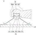
Fig. 6 is an enlarged schematic sectional view showing an example of a cross section of a part of the changeover switch 2 explained in the present application. Fig. 6 is an enlarged schematic sectional view of the section a-B shown in fig. 3A enlarged so that the relationship between the shaft portion 200 of the oscillating member 20 and the bent portion 210 of the contact member 21 can be recognized. A holding portion 200a is formed inside the shaft portion 200 of the oscillating member 20, a groove for fitting the bent portion 210 of the contact member 21 is formed in the holding portion 200a, and a frame-shaped portion formed by the bent portion 210 and the cut-and-raised portion 210a of the contact member 21 is fitted into the holding portion 200a of the oscillating member 20, whereby the contact portion is held by the oscillating member 20. The holding portion 200a has a substantially rectangular groove in front view, a frame-shaped portion formed by the bent portion 210 and the cut-and-raised portion 210a of the contact member 21 is fitted into the substantially rectangular groove, and the bent portion 210 of the contact member 21 is fitted into the groove of the holding portion 200 a. That is, the holding portion 200a of the rocking member 20 is fitted over the frame-shaped portion formed by the bent portion 210 and the cut-and-raised portion 210a of the contact member 21, and holds the contact member 21. By forming the bent portion 210 and the cut-and-raised portion 210a in the contact member 21 to form a substantially rectangular frame-shaped portion, the shaft portion 200 can be held by the substantially rectangular holding portion 200 a. For example, in the case where the contact member 21 is not formed with the cut-and-raised portion 210a, since the contact member 21 is formed of a metal thin plate, a groove for fitting needs to be formed to be elongated. In the case of forming the oscillating member 20 in which the narrow groove for holding the contact member 21 is engraved by injection molding, there is a possibility that the molding cost increases, but the molding is facilitated by making the groove engraved in the holding portion 200a rectangular shape instead of the narrow groove, so that the increase in the molding cost can be suppressed. By holding the contact member 21 by the holding portion 200a of the oscillating member 20 having the oscillating shaft as the center axis, the contact member 21 is held in a state where the plurality of movable contacts 211 extend in different directions from the respective oscillating shafts. The plurality of movable contacts 211 mentioned here extend in different directions from the swing axis, and it is meant that the angle formed by the direction in which the movable contact 211 extends and the swing axis is different for each movable contact 211.
Fig. 7 is a schematic external view showing an example of the selector switch 2 described in the present application. Fig. 7 is a schematic plan view, and in order to facilitate understanding of the relationship between the substrate 22 and the contact member 21, a part of the swinging member 20 and the outer shape of the contact member 21 are shown in a perspective view by a dashed line. On the upper surface of the substrate 22, fixed contacts 220 are formed to which the movable contacts 211 of the contact member 21 can be brought into contact. In the example of fig. 7, as the fixed contacts 220, rectangular ground fixed contacts 220a having left and right longitudinal directions are formed at two positions on the left and right of the depth side, and rectangular forward rotation fixed contacts 220b and reverse rotation fixed contacts 220c having left and right longitudinal directions are formed on the near side. Here, the forward rotation fixed contact 220b is located on the near-front left side, and the reverse rotation fixed contact 220c is located on the near-front right side. The ground fixed contact 220a is electrically connected to a ground terminal. The normal rotation fixed contact 220b is electrically connected to the load side terminal on the normal rotation side, and the reverse rotation fixed contact 220c is electrically connected to the load side terminal on the reverse rotation side.
Two adjacent brush pieces 211a of the eight brush pieces 211 formed in the contact member 21 are formed as a set and contact with the fixed contacts 220 on the substrate 22. The two sets of brush pieces 211a on the depth side of the contact member 21 illustrated in fig. 7 may each be in contact with the ground fixed contact 220 a. Further, the brush pieces 211a of the front left group may contact the forward rotation fixed contact 220b, and the brush pieces 211a of the front right group may contact the reverse rotation fixed contact 220c.
Next, the operation of the changeover switch 2 described in the present application will be described. Fig. 8A, 8B, and 8C are schematic enlarged cross-sectional views showing an example of a cross section of a part of the changeover switch 2 explained in the present application. Fig. 8A, 8B, and 8C show the operation of the down switch 2 when viewed from the front. In order to facilitate grasping of the position of the contact member 21, a schematic cross-sectional enlarged view is used. Fig. 8A shows a state in which the operation arm 201 (the operation arm 201 is not shown) of the swing member 20 extending to the left side is swung downward in front view. When the operation arm 201 of the swing member 20 swings downward, the lower swing member 20 swings left (counterclockwise) when viewed from the front, and the entire swing member 20 tilts upward and rightward. When the swinging member 20 swings, the contact member 21, which is linked with the swinging member 20 by the same swing axis, also swings left. By the left-hand swing of the contact member 21, the movable contact 211 on the left side of the contact member 21 comes into contact with the fixed contact 220 on the left side of the substrate 22. The brush piece 211a formed in the movable contact 211 comes into contact with the fixed contact 220 in accordance with the swinging of the contact member 21, and the brush piece 211a slides on the fixed contact 220 in a state of being pressed against the fixed contact 220 by the swinging of the contact member 21. Since the contact member 21 is formed of a thin metal plate, by being crimped on the fixed contact 220, the brush piece 211a maintains a state of being bent backward and abutted, and slides on the fixed contact 220. In this way, after the movable contact 211 is brought into contact with the fixed contact 220, the movable contact 211 can be brought into firm contact with the fixed contact 220 by further pressure-bonding, and further, impurities on the fixed contact 220 can be expected to be removed by sliding the movable contact 211 in a state of contact with the fixed contact 220. In the state of fig. 8A, since the brush piece 211a of the movable contact 211 is in contact with the left-side grounded fixed contact 220a and the forward rotation fixed contact 220b, the left-side grounded fixed contact 220a and the forward rotation fixed contact 220b are electrically connected, and the ground terminal and the forward rotation side load side terminal are in a conductive state. In this state, when the operation member 30 of the power switch 3 is pressed, the electric motor included in the electric device as the electric load M is energized in the forward direction, and the electric motor is rotated forward.
Fig. 8B shows a state in which the operation arm 201 of the swing member 20 is swung upward. When the operation arm 201 of the swing member 20 swings upward, the lower swing member 20 swings rightward (clockwise) as viewed from the front, and the entire swing member 20 tilts downward rightward. The contact member 21, which is interlocked with the swinging member 20 about the same swinging axis, is also swung in the right direction by the swinging of the swinging member 20. By the contact member 21 swinging rightward, the movable contact 211 on the right side of the contact member 21 comes into contact with the fixed contact 220 on the right side of the substrate 22. In the state of fig. 8B, since the brush piece 211a of the movable contact 211 is in contact with the right fixed grounding contact 220a and the fixed counter contact 220c, the right fixed grounding contact 220a and the fixed counter contact 220c are electrically connected, and the grounding terminal and the load-side terminal on the counter side are in a conductive state. In this state, when the operation member 30 of the power switch 3 is pressed, the electric motor included in the electric device as the electric load M is energized in the reverse direction, and the electric motor is reversed.
Fig. 8C shows a state where the swing member 20 is held substantially horizontally. By making the swinging member 20 substantially horizontal as shown in fig. 8C, the movable contact 211 of the contact member 21 is held in a state of being separated from the fixed contact 220. The switching device 1 described in the present application may be, for example, in a mechanically restricted locked state so that the power switch 3 cannot be pressed. When the power switch 3 is in the locked state, the swing of the swing member 20 is also restricted in conjunction with the locking mechanism of the power switch 3. The restricting of the swing member 20 in conjunction with the locking mechanism of the power switch 3 is, for example, fixed in the state shown in fig. 8C.
< second embodiment >
The second embodiment is a mode in which the shapes and functions of various members included in the selector switch 2 are different from those of the first embodiment. In the following description, the same reference numerals as those in the first embodiment are used for the same configurations as those in the first embodiment, and the first embodiment is referred to, and a part of the description is omitted.
Fig. 9 is a schematic perspective view showing an example of an external appearance of the switch device 1 described in the present application. The switching device 1 illustrated in fig. 9 includes: a change-over switch 2, a power switch 3, a circuit part 4, and the like.
Fig. 10 is a schematic circuit diagram showing a simplified example of a part of the circuit configuration of the switching device 1 described in the present application. The circuit unit 4 has a circuit that is opened, closed, or turned on and off by the power switch 3 and the changeover switch 2. Fig. 10 shows a part of the circuit of the electric device in association with a part of the circuit unit 4. In fig. 10, a part of a circuit in which a portion indicated by a broken line is mounted in the switchgear 1 is generally indicated, and the circuit in the switchgear 1 can be electrically connected to the electric load M in the electric device. The power switch 3 opens and closes between a ground terminal and a power source side terminal that supplies power to the power load M. The selector switch 2 opens and closes between the ground terminal and the load-side terminal connected to the power load M, but two terminals may be disposed as the load-side terminal, and by operating the selector switch 2, the ground terminal and either one of the two load-side terminals can be turned on and off. The fixing may be performed in a neutral state in which none of the load side terminals is connected.
Next, the structure of the changeover switch 2 will be described. Fig. 11A and 11B are schematic external views showing an example of the external appearance of the selector switch 2 described in the present application. Fig. 11A is a schematic plan view, and fig. 11B is a schematic front view. Fig. 11A and 11B also show the circuit unit 4 in order to facilitate understanding of the relationship with fig. 9. As described above, the selector switch 2 includes the oscillating member 20, the contact member 21, and the substrate 22. The swing member 20 of the selector switch 2 includes a shaft portion 200 formed in a columnar shape, and an elongated operation arm 201 formed in a substantially hexagonal plate shape is formed on one bottom surface of the shaft portion 200.
Fig. 12A and 12B are schematic external views showing an example of the external appearance of the contact member 21 included in the selector switch 2 described in the present application. Fig. 12A is a schematic plan view, and fig. 12B is a schematic front view. Fig. 13 is a schematic perspective view showing an example of an appearance of the contact member 21 of the selector switch 2 described in the present application. The contact member 21 has: two bent portions 210 bent at substantially right angles, and movable contacts 211 extending from the bent portions 210 in different directions from each other. Movable contact 211 extends obliquely downward after extending leftward and rightward from bent portion 210, and the vicinity of the tip of movable contact 211 contacts substrate 22 by swinging. Further, a fixed contact 212 extending diagonally downward to the right is branched from the middle of the movable contact 211 extending leftward. The tip of the constant contact 212 is formed as a brush piece 212a, and maintains a state of contact with the substrate 22 regardless of the state of oscillation of the contact member 21.
The bent portion 210 is located near the substantial center of the contact member 21. The bent portion 210 is formed in a frame shape having two corners bent at substantially right angles in a front view and lacking one side. Cut-and-raised portions 210a cut out to the other vertical frame are formed at positions facing the two vertical frames. That is, the bent portion 210 of the contact member 21 is engaged with the cut-and-raised portion 210a to form a frame-shaped portion having a substantially rectangular frame shape. The frame-shaped portion formed by the bent portion 210 and the cut-and-raised portion 210a is disposed in the shaft portion 200 of the oscillating member 20.
Fig. 14 is an enlarged schematic sectional view showing an example of a cross section of a part of the changeover switch 2 explained in the present application. Fig. 14 is an enlarged schematic sectional view of the C-D section shown in fig. 11A so that the relationship between the shaft portion 200 of the oscillating member 20 and the bent portion 210 of the contact member 21 can be recognized. A holding portion 200a is formed inside the shaft portion 200 of the rocking member 20, a groove into which the bent portion 210 of the contact member 21 is fitted is engraved in the holding portion 200a, and a frame-shaped portion formed by the bent portion 210 and the cut-and-raised portion 210a of the contact member 21 is fitted into the holding portion 200a of the rocking member 20, whereby the contact portion is held by the rocking member 20. The holding portion 200a has a substantially rectangular groove when viewed from the front, a frame-shaped portion formed by the bent portion 210 and the cut-and-raised portion 210a of the contact member 21 is fitted into the substantially rectangular groove, and the bent portion 210 of the contact member 21 is fitted into the groove of the holding portion 200 a. That is, the holding portion 200a of the rocking member 20 is fitted to the frame-shaped portion formed by the curved portion 210 and the cut-and-raised portion 210a of the contact member 21, and holds the contact member 21.
Fig. 15 is a schematic external view showing an example of the selector switch 2 described in the present application. Fig. 15 is a schematic plan view, and in order to facilitate understanding of the relationship between the substrate 22 and the contact member 21, a part of the swinging member 20 and the outer shape of the contact member 21 are shown in a perspective view by a dashed-dotted line. On the upper surface of the substrate 22, a fixed contact 220 is formed to which the movable contact 211 of the contact member 21 can be brought into contact. In the example of fig. 15, as the fixed contacts 220, rectangular ground fixed contacts 220a having front and rear longitudinal directions are formed at the center, rectangular forward rotation fixed contacts 220b having front and rear longitudinal directions are formed on the left side, and rectangular reverse rotation fixed contacts 220c having front and rear longitudinal directions are formed on the right side.
The brush piece 211a formed in the contact member 21 is formed by combining two pieces, and is brought into contact with the fixed contact 220 on the substrate 22. In the contact member 21 illustrated in fig. 15, the brush piece 211a of the left movable contact 211 is contactable with the forward rotation fixed contact 220b, and the brush piece 211a of the right movable contact 211 is contactable with the reverse rotation fixed contact 220c. In addition, the brush piece 212a of the constant contact 212 is in contact with the ground fixed contact 220 a. The constant contact 212 is in contact with the ground fixed contact 220a regardless of the swinging condition of the contact member 21. Therefore, the movable contact 211 of the contact member 21 and the ground fixed contact 220a formed on the substrate 22 are electrically connected by the constant contact 212 regardless of the swinging state of the contact member 21.
Next, the operation of the changeover switch 2 described in the present application will be described. Fig. 16A, 16B, and 16C are enlarged schematic sectional views showing an example of a cross section of a part of the changeover switch 2 described in the present application. Fig. 16A, 16B, and 16C show the operation of the down switch 2 when viewed from the front. In order to facilitate grasping of the position of the contact member 21, a schematic cross-sectional enlarged view is used. Fig. 16A shows a state in which the operation arm 201 of the swing member 20 is swung downward on the left side in front view. When the operation arm 201 of the swing member 20 swings downward, the swing member 20 swings leftward as viewed from the front, and the entire swing member 20 tilts upward and rightward. The contact member 21, which is linked by the rocking member 20 being integrated with the rocking shaft, also rocks leftward by the rocking of the rocking member 20. By the left-hand swing of the contact member 21, the movable contact 211 on the left side of the contact member 21 comes into contact with the fixed contact 220 on the left side of the substrate 22. The fixed contact 212 of the contact member 21 is kept in contact with the fixed contact 220 at the center on the substrate 22, and when the contact member 21 swings, the fixed contact 212 slides in contact with the fixed contact 220. In fig. 16A, in a state where the brush piece 212a of the fixed contact 212 is in contact with the fixed ground contact 220a, the brush piece 211a of the left movable contact 211 is in contact with the fixed forward rotation contact 220b, and therefore, the fixed ground contact 220a and the fixed forward rotation contact 220b are electrically connected, and the ground terminal and the load-side terminal on the forward rotation side are in a conductive state. In this state, when the operation member 30 of the power switch 3 is pressed, the electric motor included in the electric device as the electric load M is energized in the forward direction, and the electric motor is rotated forward.
Fig. 16B shows a state in which the operation arm 201 of the swing member 20 is swung upward. When the operation arm 201 of the swing member 20 swings upward, the swing member 20 swings rightward in front view, and the entire swing member 20 tilts downward rightward. The contact member 21, which is interlocked with the swinging member 20 about the same swinging axis, is also swung in the right direction by the swinging of the swinging member 20. By the contact member 21 swinging rightward, the movable contact 211 on the right side of the contact member 21 comes into contact with the fixed contact 220 on the right side of the substrate 22. In fig. 16B, in a state where the brush piece 212a of the fixed contact 212 is in contact with the central grounded fixed contact 220a, the brush piece 211a of the right movable contact 211 is in contact with the inverted fixed contact 220c, and therefore the grounded fixed contact 220a and the inverted fixed contact 220c are electrically connected, and the ground terminal and the load-side terminal on the inverted side are in a conductive state. In this state, when the operation member 30 of the power switch 3 is pressed, the electric motor included in the electric device as the electric load M is energized in the reverse direction, and the electric motor is reversed.
Fig. 16C shows a state where the swing member 20 is held substantially horizontally. By making the swinging member 20 substantially horizontal as shown in fig. 16C, the fixed contact 212 of the contact member 21 is brought into contact with the grounded fixed contact 220a, but the movable contact 211 of the contact member 21 is held in a state of being separated from the fixed contact 220. The switching device 1 described in the present application may be, for example, in a mechanically restricted locked state so that the power switch 3 cannot be pressed. When the power switch 3 is in the locked state, the swing of the swing member 20 is also restricted in conjunction with the locking mechanism of the power switch 3. The restricting of the swing member 20 in conjunction with the locking mechanism of the power switch 3 is, for example, fixed in the state shown in fig. 16C.
As described above by way of example of the first and second embodiments, the change-over switch 2 included in the switching device 1 described in the present application includes: a swing member 20 that swings in response to an operation from the outside; a contact member 21 that swings on the same swing axis as the swing member 20 and has a plurality of movable contacts 211 extending in different directions from each other with respect to the swing axis; and a substrate 22 on which a fixed contact 220 that can be contacted by the movable contact 211 of the contact member 21 is formed.
In detail, the switch device 1 exemplified as the first and second embodiments includes the selector switch 2 composed of the swing member 20, the contact member 21, the substrate 22, and the like. A plurality of fixed contacts 220 are formed on the substrate 22 so as to be positioned on a virtual parallel plane having a parallel relationship with respect to the oscillation axis of the oscillating member 20. Although the plurality of fixed contacts 220 are located on the virtual parallel plane, they are not necessarily exactly parallel to the oscillating member 20, and are allowed to have an error to such an extent that no problem occurs in operation. That is, the parallel relationship mentioned here indicates a substantially parallel relationship including a slight error. The plurality of fixed contacts 220 are formed on both sides of a virtual orthogonal plane that is orthogonal to the virtual parallel plane and includes the swing axis of the swing member 20. In the first embodiment, an example is shown in which the ground fixed contact 220a and the normal rotation fixed contact 220b are formed on the first side (left side) of the orthogonal surface, and the ground fixed contact 220a and the reverse rotation fixed contact 220c are formed on the second side (right side). In the second embodiment, the normal rotation fixed contact 220b is formed on the first side of the orthogonal surface, and the reverse rotation fixed contact 220c is formed on the second side. The contact member 21 that swings on the same swing axis as the swing member 20 has a plurality of movable contacts 211 extending in different directions from each other with respect to the virtual orthogonal plane. That is, the contact member 21 has the movable contacts 211 on both sides with the swing shaft of the swing member 20 interposed therebetween. The substrate 22 on which the fixed contact 220 is formed is orthogonal to an orthogonal plane including the oscillation axis.
The change-over switch 2 included in the switch device 1 configured as described above is configured such that the movable contact 211 that comes into contact with the fixed contact 220 formed on the substrate 22 is switched by the swinging of the contact member 21 in conjunction with the swinging of the swinging member 20. That is, with such a simple structure as the swing member 20, the contact member 21, and the substrate 22, the selector switch 2 can be operated differently for each swing direction, that is, for each direction in which the swing member 20 is inclined, and there is an advantageous effect that the accessory structure can be simplified. In particular, when the rocking member 20 and the contact member 21 are formed as the same component by processing the same material, the number of components can be reduced. The reduction in the number of components is associated with suppression of various cost increases such as manufacturing cost, assembly cost, and management cost.
The present invention is not limited to the embodiments described above, and can be implemented in other various ways. Therefore, the above embodiments are merely exemplary in all aspects and should not be construed as limiting the present invention. The technical scope of the present invention is defined by the claims, and is not limited to the description. Further, all the modifications and variations falling within the equivalent range of the scope of the claims are included in the scope of the present invention.
For example, the arrangement of the fixed contacts 220 described in the above embodiment is merely an example, and the arrangement may be changed to various arrangements, and the movable contact 211 side may be designed as appropriate. For example, in the above-described embodiment, the mode in which the normal rotation/reverse rotation of the power load M is switched by the changeover switch 2 is shown, but the changeover switch 2 of the present invention is not limited thereto, and can be applied to various kinds of changeover circuits. For example, various methods such as switching between fast and slow rotation speeds of the electric load M can be used. Further, the electric load M other than the electric motor may be developed.
In the above-described embodiment, the contact member 21 is formed by processing a single thin metal plate, but the present invention is not limited to this, and the pivot axis of each movable contact 211 may be the same as the pivot axis of the pivot member 20. For example, various modes such as a mode in which a thin metal plate is used for each movable contact 211 and each thin metal plate is inserted into the shaft portion 200 of the oscillating member 20 can be developed.
In the above embodiment, the contact member 21 having the bent portion 210 formed in a frame shape by bending two portions at right angles is exemplified, but the bent portion may be one portion, or may be three or more portions. When the bent portion is one point, both sides of the bent portion are both ends of the bent portion 210, and the movable contact 211 extends from both ends. When the number of bending portions is three or more, both end portions of the plurality of bending portions are both ends of the bending portion 210, and the movable contact 211 extends from both ends.
In the above embodiment, the movable contact 211 and the fixed contact 220 are electrically connected to each other by maintaining the brush-shaped fixed contact 212 in contact with the fixed contact 220, but the present invention is not limited to this. For example, various methods such as providing the fixed contacts 212 electrically connecting the movable contact 211 and the fixed contacts 220 as internal wiring lines can be used.
In the above embodiment, the rocking member 20 is shown as a mode in which the holding portion 200a is fitted over the frame-shaped portion formed by the bent portion 210 and the cut-and-raised portion 210a in the shaft portion 200 to hold the contact member 21, but the present invention is not limited to this. For example, various forms may be adopted such as holding the contact member 21 by fitting the shaft portion 200 into a frame-like portion formed by the bent portion 210 and the cut-and-raised portion 210a.
Description of the reference numerals
1a switching device; 2, a change-over switch; 20a swing member; 200a shaft portion; 200a holding part; 201 operating an arm; 21 a contact member; 210 bending portions (frame-shaped portions); 210a cut-and-raised portion (frame-shaped portion); 211a movable contact; 212a constant contact; 22 a substrate; 220 fixed contacts; 3 power switch.
Claims (6)
1. A change-over switch, comprising:
a swing member that swings in response to an operation from the outside;
a contact member that swings together with the swing member on the same swing axis and has a plurality of movable contacts extending in different directions from each other;
a substrate on which a fixed contact point that can be contacted by the movable contact point of the contact point member is formed;
a movable contact that contacts a fixed contact formed on the substrate is switched by the swinging of the contact member in conjunction with the swinging of the swinging member,
and a constant contact point for electrically connecting a movable contact point of the contact point member and a fixed contact point which cannot be directly connected with the movable contact point regardless of a swing condition of the contact point member,
the constant contact is part of the contact member,
the fixed contact slides in a state of being in contact with the fixed contact connected to the fixed contact by the swing of the contact member.
2. A change-over switch, comprising:
a swing member that swings in response to an operation from the outside;
a substrate having a plurality of fixed contacts which are located on a parallel surface parallel to a swing axis of the swing member and are formed on both sides of an orthogonal surface orthogonal to the parallel surface and including the swing axis of the swing member;
a contact member that swings together with the swing member on the same swing axis, and has a plurality of movable contacts extending in different directions from each other with respect to the orthogonal surface;
a movable contact that contacts a fixed contact formed on the substrate is switched by the swinging of the contact member in conjunction with the swinging of the swinging member,
and a constant contact point for electrically connecting a movable contact point of the contact point member and a fixed contact point which cannot be directly connected with the movable contact point regardless of a swing condition of the contact point member,
the constant contact is part of the contact member,
the fixed contact slides in a state of being in contact with the fixed contact connected to the fixed contact by the swing of the contact member.
3. The diverter switch according to claim 1 or 2,
the contact member having the plurality of movable contacts is formed of one conductive plate.
4. The diverter switch according to claim 1 or 2,
the swing member has a shaft portion through which a swing shaft passes,
the contact member is formed of a single conductive plate having a bent portion,
the bent portion is disposed within the shaft portion,
each movable contact extends from both ends of the bent portion.
5. The transfer switch of claim 4,
the contact member has a cut-and-raised portion cut and raised so as to form a frame-shaped portion in cooperation with the bent portion,
the swinging member has a holding portion that is fitted to a frame-shaped portion formed by the bent portion and the cut-and-raised portion to hold the contact member.
6. A switching device, comprising:
a power switch that opens and closes a circuit that supplies power to an electric load;
the changeover switch of any one of claims 1 to 5, which switches power supplied to the electric load.
Applications Claiming Priority (3)
| Application Number | Priority Date | Filing Date | Title |
|---|---|---|---|
| JP2018-043267 | 2018-03-09 | ||
| JP2018043267A JP6954189B2 (en) | 2018-03-09 | 2018-03-09 | Changeover switch and switch device |
| PCT/JP2019/001039 WO2019171770A1 (en) | 2018-03-09 | 2019-01-16 | Change-over switch and switch device |
Publications (2)
| Publication Number | Publication Date |
|---|---|
| CN111699538A CN111699538A (en) | 2020-09-22 |
| CN111699538B true CN111699538B (en) | 2023-03-14 |
Family
ID=67847093
Family Applications (1)
| Application Number | Title | Priority Date | Filing Date |
|---|---|---|---|
| CN201980012690.3A Active CN111699538B (en) | 2018-03-09 | 2019-01-16 | Change-over switch and switch device |
Country Status (6)
| Country | Link |
|---|---|
| US (1) | US11201023B2 (en) |
| JP (1) | JP6954189B2 (en) |
| CN (1) | CN111699538B (en) |
| DE (1) | DE112019001235T5 (en) |
| TW (1) | TWI699951B (en) |
| WO (1) | WO2019171770A1 (en) |
Families Citing this family (1)
| Publication number | Priority date | Publication date | Assignee | Title |
|---|---|---|---|---|
| CN117095968A (en) * | 2022-05-13 | 2023-11-21 | 博世电动工具(中国)有限公司 | Rotary reversing switch and switch assembly for power tool |
Family Cites Families (14)
| Publication number | Priority date | Publication date | Assignee | Title |
|---|---|---|---|---|
| US5889242A (en) * | 1996-10-17 | 1999-03-30 | Matsushita Electric Industrial Co., Ltd. | Multidirectional operating switch and multidirectional operating apparatus using the same |
| JP4433283B2 (en) | 2004-02-06 | 2010-03-17 | タイコエレクトロニクスジャパン合同会社 | Switch and device using the same |
| JP4326987B2 (en) * | 2004-03-11 | 2009-09-09 | アルプス電気株式会社 | Switch device |
| JP4457877B2 (en) * | 2004-12-10 | 2010-04-28 | パナソニック株式会社 | Remote control transmitter |
| TW200820300A (en) | 2006-10-30 | 2008-05-01 | Excel Cell Elect Co Ltd | Micro program switch |
| JP2008177091A (en) * | 2007-01-19 | 2008-07-31 | Tokai Rika Co Ltd | Switch device |
| JP5153675B2 (en) | 2009-02-10 | 2013-02-27 | オムロンオートモーティブエレクトロニクス株式会社 | Opening and closing body drive device |
| JP2010250944A (en) | 2009-04-10 | 2010-11-04 | Panasonic Corp | Lever switch |
| JP2012001188A (en) * | 2010-06-21 | 2012-01-05 | Tokai Rika Co Ltd | Device for operation of vehicle apparatus |
| JP2013012371A (en) * | 2011-06-29 | 2013-01-17 | Smk Corp | Switch |
| JP5938554B2 (en) | 2012-01-17 | 2016-06-22 | パナソニックIpマネジメント株式会社 | Lever switch |
| CN103456545B (en) * | 2012-05-29 | 2016-05-11 | 阿尔卑斯电气株式会社 | Shake operation type switch apparatus |
| JP6287201B2 (en) * | 2013-12-27 | 2018-03-07 | オムロン株式会社 | Terminal connection structure |
| JP2015219965A (en) | 2014-05-14 | 2015-12-07 | 佐鳥エス・テック株式会社 | Trigger switch |
-
2018
- 2018-03-09 JP JP2018043267A patent/JP6954189B2/en active Active
-
2019
- 2019-01-16 DE DE112019001235.5T patent/DE112019001235T5/en active Pending
- 2019-01-16 CN CN201980012690.3A patent/CN111699538B/en active Active
- 2019-01-16 WO PCT/JP2019/001039 patent/WO2019171770A1/en active Application Filing
- 2019-01-16 US US16/971,397 patent/US11201023B2/en active Active
- 2019-01-31 TW TW108103671A patent/TWI699951B/en active
Also Published As
| Publication number | Publication date |
|---|---|
| WO2019171770A1 (en) | 2019-09-12 |
| TW201939861A (en) | 2019-10-01 |
| US20210050165A1 (en) | 2021-02-18 |
| US11201023B2 (en) | 2021-12-14 |
| DE112019001235T5 (en) | 2020-12-03 |
| CN111699538A (en) | 2020-09-22 |
| JP2019160490A (en) | 2019-09-19 |
| JP6954189B2 (en) | 2021-10-27 |
| TWI699951B (en) | 2020-07-21 |
Similar Documents
| Publication | Publication Date | Title |
|---|---|---|
| CN111699538B (en) | Change-over switch and switch device | |
| JP2008004322A (en) | Switch | |
| CN1200438C (en) | Contact element | |
| CN103299387A (en) | Switch device | |
| US5357069A (en) | Structure of sliding switch contacts | |
| JP4066336B2 (en) | Switch device | |
| US6969812B2 (en) | Switch device | |
| JP5358391B2 (en) | Lever switch | |
| KR100583877B1 (en) | Mirror switch apparatus | |
| EP1930927A1 (en) | Electric switch with a pivoting switching member | |
| CN218038941U (en) | Breaking structure for switch and switch with breaking structure | |
| JP2002313194A (en) | Protection device | |
| US10903609B2 (en) | Connector | |
| JP2000348570A (en) | Switching device | |
| WO2023007818A1 (en) | Electric connection component and switch device | |
| JP2001351477A (en) | Switch device | |
| JP2881815B2 (en) | Operation switch of car mirror | |
| JP2008097935A (en) | Seat switch | |
| CN106206135B (en) | Switching device | |
| KR101155282B1 (en) | Vehicular lever switching unit | |
| JP2004171790A (en) | Combination switch | |
| EP3166119B1 (en) | Switch | |
| JPH0235157Y2 (en) | ||
| JP4731465B2 (en) | Switch device | |
| JPH07296681A (en) | Multi-way switch |
Legal Events
| Date | Code | Title | Description |
|---|---|---|---|
| PB01 | Publication | ||
| PB01 | Publication | ||
| SE01 | Entry into force of request for substantive examination | ||
| SE01 | Entry into force of request for substantive examination | ||
| GR01 | Patent grant | ||
| GR01 | Patent grant |