CN111681923A - Circuit breaker - Google Patents
Circuit breaker Download PDFInfo
- Publication number
- CN111681923A CN111681923A CN202010505461.XA CN202010505461A CN111681923A CN 111681923 A CN111681923 A CN 111681923A CN 202010505461 A CN202010505461 A CN 202010505461A CN 111681923 A CN111681923 A CN 111681923A
- Authority
- CN
- China
- Prior art keywords
- circuit breaker
- driven gear
- circuit
- transmission piece
- gear
- Prior art date
- Legal status (The legal status is an assumption and is not a legal conclusion. Google has not performed a legal analysis and makes no representation as to the accuracy of the status listed.)
- Pending
Links
Images


Classifications
-
- H—ELECTRICITY
- H01—ELECTRIC ELEMENTS
- H01H—ELECTRIC SWITCHES; RELAYS; SELECTORS; EMERGENCY PROTECTIVE DEVICES
- H01H71/00—Details of the protective switches or relays covered by groups H01H73/00 - H01H83/00
- H01H71/10—Operating or release mechanisms
- H01H71/1009—Interconnected mechanisms
-
- H—ELECTRICITY
- H01—ELECTRIC ELEMENTS
- H01H—ELECTRIC SWITCHES; RELAYS; SELECTORS; EMERGENCY PROTECTIVE DEVICES
- H01H71/00—Details of the protective switches or relays covered by groups H01H73/00 - H01H83/00
- H01H71/10—Operating or release mechanisms
- H01H71/66—Power reset mechanisms
- H01H71/70—Power reset mechanisms actuated by electric motor
Landscapes
- Breakers (AREA)
Abstract
The invention relates to the field of low-voltage electrical appliances, in particular to a circuit breaker, which comprises a circuit breaker shell, an electric mechanism, an operating mechanism, a moving contact and a static contact, wherein the electric mechanism and the operating mechanism are respectively arranged in the circuit breaker shell; the electric mechanism comprises a driving gear piece and a driven gear which are respectively pivoted on the shell of the circuit breaker, the operating mechanism comprises a transmission piece which is pivoted on the shell of the circuit breaker, and the driven gear and the transmission piece are coaxially arranged and are in driving fit; the driving gear piece is in driving fit with the driven gear, the driven gear drives the transmission piece to rotate so as to close the circuit breaker, and an energy storage spring is arranged between the driven gear and the transmission piece; according to the circuit breaker, the energy storage spring ensures the closing effectiveness of the circuit breaker, and the service life of the circuit breaker is longer.
Description
Technical Field
The invention relates to the field of low-voltage electrical appliances, in particular to a circuit breaker.
Background
The existing plug-in circuit breaker mostly has the following problems:
the circuit breaker electric mechanism realizes automatic switching-on through a driving handle mechanism, enables the circuit breaker to trip to realize automatic switching-off through the driving handle mechanism or a lock catch of a driving operation mechanism, is easy to wear by a corresponding matching mechanism, and leads to a complex structure for realizing the mutual noninterference of automatic switching-on and manual switching-off. In addition, in the electric mechanism of the existing circuit breaker, the motor control is processed through a position sensor and a chip, the position sensor transmits the closing and opening positions of the circuit breaker to the chip, the chip controls the motor to rotate forwards or reversely to achieve closing and opening and return to the initial position (namely, the manual opening and closing position of the circuit breaker is not influenced), and the chip is easily interfered by the outside, so that the position detection is unreliable, and the action reliability of the circuit breaker is influenced.
Second, current circuit breaker, its electric mechanism leans on the gear hard drive, and long-time back of using appears the structure wearing and tearing easily, often can lead to the not in place condition of transmission, shows that circuit breaker switching-on or separating brake are not in place.
When the existing circuit breaker is switched between a manual working mode and an automatic working mode, the operation is inconvenient, and the working reliability of a manual and automatic switching device is not high.
And the overall space dimension specification of the conventional circuit breaker is too large, so that the conventional circuit breaker does not meet the trend and the requirement of miniaturization development of the circuit breaker.
Fifth, in the existing circuit breaker, the control of the motor of the electric mechanism of the circuit breaker is often realized by a complex physical structure and a complex circuit, so that the overall structure of the circuit breaker is complex and the reliability of the circuit breaker is poor.
Disclosure of Invention
The invention aims to overcome the defects of the prior art and provides a breaker, wherein an energy storage spring of the breaker ensures the closing effectiveness of the breaker, and the breaker has longer service life.
In order to achieve the purpose, the invention adopts the following technical scheme:
a circuit breaker comprises a circuit breaker shell 1, an electric mechanism 3, an operating mechanism 5, a movable contact 1a and a static contact 1b, wherein the electric mechanism 3, the operating mechanism 5, the movable contact 1a and the static contact 1b are respectively arranged in the circuit breaker shell 1; the electric mechanism 3 comprises a driving gear piece 305 and a driven gear piece 306 which are respectively and pivotally arranged on the circuit breaker shell 1, the operating mechanism 5 comprises a transmission piece 501 which is pivotally arranged on the circuit breaker shell 1, and the driven gear piece 306 and the transmission piece 501 are coaxially arranged and are in driving fit;
the driving gear piece 305 is in driving fit with the driven gear 306, the driven gear 306 drives the transmission piece 501 to rotate so as to close the circuit breaker, and an energy storage spring 3-5 is arranged between the driven gear 306 and the transmission piece 501.
Preferably, the energy storage spring 3-5 is a torsion spring, and comprises a spring main body 3-50, a first spring arm 3-51 and a second spring arm 3-52; the spring main bodies 3-50 are arranged between the driven gear 306 and the transmission piece 501, the first spring arms 3-51 are in limit fit with the transmission piece 501, and the second spring arms 3-52 are in limit fit with the driven gear 306.
Preferably, the transmission member 51 includes a driven gear limiting groove 501 and a transmission member 51 disposed at one side thereof, the driven gear 306 includes a driven gear body 306-2 and a first sector gear portion 306-1 disposed at one side of the driven gear body 306-2, the driven gear body 306-2 and the transmission member 501 are coaxially and pivotally disposed on the circuit breaker housing 1, the first sector gear portion 306-1 is disposed in the driven gear limiting groove 501 and the spring main body 3-50 of the energy storage spring 3-5 is located between the driven gear body 306-2 and the transmission member 51.
Preferably, the first sector gear portion 306-1 includes a first sector gear portion head end face 306-10 and a first sector gear portion tail end face 306-11 respectively disposed at two ends thereof, the transmission member 501 further includes a driven gear limiting groove head end face 501-6 and a driven gear limiting groove tail end face 501-4 disposed at two ends of the driven gear limiting groove 501-306, the first sector gear portion head end face 306-10 abuts against the driven gear limiting groove head end face 501-6, and a first movement gap is disposed between the first sector gear portion tail end face 306-11 and the driven gear limiting groove tail end face 501-4.
Preferably, the driven gear 306 further comprises a driven gear spring limiting hole 306-3 arranged on the driven gear body 306-2, the transmission member 501 further comprises a transmission member spring limiting groove 501-5 arranged at one end of the driven gear limiting groove 501 and the driven gear limiting groove 306, and the transmission member spring limiting groove 501-5 and the driven gear limiting groove tail end face 501-4 are located at the same end of the transmission gear limiting groove 501 and the driven gear limiting groove 306; the first spring arms 3-51 are in limit fit with the transmission piece spring limiting grooves 501-5, and the second spring arms 3-52 are in limit fit with the driven gear spring limiting holes 306-3.
Preferably, the transmission member 501 further comprises a transmission member main body 501-0 and a transmission member spring assembly groove 501-7 arranged on one side of the transmission member main body 501-0, and the driven gear limiting groove 501-306 is arranged on one side of the transmission member spring assembly groove 501-7; the driven gear body 306-2 and the first sector gear portion 306-1 are arranged in a staggered manner, and the first sector gear portion 306-1 is offset to the side of the transmission member 501 relative to the driven gear body 306-2; the spring main bodies 3-50 are arranged in the transmission piece spring assembly grooves 501-7 and limited between the driven gear body 306-2 and the transmission piece main body 501-0.
Preferably, the circuit breaker further comprises a button mechanism 2 arranged in the circuit breaker shell 1, the button mechanism 2 comprises a button member 201 arranged on the circuit breaker shell 1 in a sliding manner, and the button mechanism 2 is connected with the transmission member 501 in a driving manner; the button 201 is pressed/pulled to drive the operation mechanism 5 to act, so that the breaker is switched on/off.
Preferably, the button mechanism 2 further comprises a connecting member 204 slidably disposed on the circuit breaker housing 1, a first connecting rod 202 having two ends connected to the button member 201 and the connecting member 204, respectively, and a second connecting rod 203 having two ends connected to the connecting member 204 and the transmission member 501, respectively; the drive gear member 305 is in driving engagement with the connecting member 204.
Preferably, the operating mechanism 5 further comprises a rotating plate 505 pivotally disposed on the circuit breaker housing 1, a trip catch 503 and a latch 504 pivotally disposed on the rotating plate 505 and respectively engaged with the trip catch, a third link 502 having two ends respectively connected to the driving member 501 and the trip catch 503, and a second return spring 506 for driving the rotating plate 504; one end of the movable contact 1a is connected with the rotating plate 505.
Preferably, the transmission member 501 is a cylindrical structure, and comprises a transmission member body 501-0, a transmission member spring assembly groove 501-7 and a driven gear limiting groove 501-306 arranged on one side of the transmission member body 501-0, and a transmission member shaft hole 501-3, a first transmission member connecting hole 501-1 and a second transmission member connecting hole 501-2 respectively arranged on the transmission member body 501-0; the transmission member spring assembly groove 501-7 and the driven gear limiting groove 501-306 are positioned on the same side of the transmission member body 501-0, and the driven gear limiting groove 501-306 is arranged on one side of the transmission member spring assembly groove 501-7; the transmission piece shaft hole 501-3, the first transmission piece connecting hole 501-1 and the second transmission piece connecting hole 501-2 are positioned at three vertex points of a triangle, the first transmission piece connecting hole 501-1 is arranged close to the driven gear limiting groove 501-306, the transmission piece 501 is pivoted through the transmission piece shaft hole 501-3, the first transmission piece connecting hole 501-1 is connected with the second connecting rod 203 of the button mechanism 2, and the second transmission piece connecting hole 501-2 is connected with the third connecting rod 502 of the operating mechanism 5.
Preferably, the driven gear 306 comprises a driven gear body 306-2, a first sector gear portion 306-1, and a driven gear shaft hole 306-4 and a driven gear spring limiting hole 306-3 respectively arranged on the driven gear body 306-2; the driven gear body 306-2 comprises a body base plate 306-20, a body limiting table 306-21 and a body spring limiting table 306-22 which are coaxially arranged in sequence and have diameters which are reduced in sequence, the body base plate 306-20 is abutted against one side of the transmission piece body 501-0 of the transmission piece 501, the body limiting table 306-21 is inserted into a transmission piece spring assembling groove 501-7 of the transmission piece 501, and the body spring limiting table 306-22 is inserted into the middle of a spring main body 3-50 of the energy storage spring 3-5; one end of the first fan-shaped gear part 306-1 is connected with one side of the body substrate 306-20 connected with the body limit table 306-21 and the outer peripheral edge of the body limit table 306-21 respectively.
Preferably, the transmission member 501 further includes a stroke limiting groove 501-8, and the circuit breaker housing 1 further includes a positioning block table 102 disposed on one side of the transmission member 501; when the circuit breaker is in an opening state, the side wall of one end of the stroke limiting groove 510-8 is in limiting fit with the in-place stop table 102, and when the circuit breaker is in a closing state, the side wall of the other end of the stroke limiting groove 510-8 is in limiting fit with the in-place stop table 102.
Preferably, the driving gear 305 rotates from the first initial position to the first direction to be meshed with the driven gear 306, the driving gear 305 continues to rotate and drives the driven gear 306 to rotate to the second direction, the driven gear 306 drives the transmission member 501 to rotate to the second direction through the energy storage spring 3-5, after the circuit breaker is closed, the driving gear 305 continues to rotate to the first direction and drives the driven gear 306 to rotate to the second direction relative to the transmission member 501, and the energy storage spring 3-5 stores energy until the driving gear 305 rotates to the middle position and is disengaged from the driven gear 306.
According to the circuit breaker, the energy storage spring is arranged between the driven gear of the electric mechanism and the transmission part of the operating mechanism, after the circuit breaker is closed, the driving gear part of the electric mechanism can drive the driven gear to rotate towards the second direction relative to the transmission part, so that the energy storage spring stores energy, the circuit breaker is closed in place, namely, the circuit breaker is effectively closed, the power utilization safety of a user is improved, and particularly, after the electric mechanism is used for a long time, the problem that the automatic closing of the circuit breaker is not in place due to the fact that the gears are abraded and matched with each other or the position detection error of a circuit board occurs is solved.
Drawings
Fig. 1 is a schematic structural view of the circuit breaker of the present invention, showing at least the specific structures of a button mechanism, an electric mechanism and an operating mechanism;
FIG. 2 is a schematic view of the construction of the connector of the present invention;
FIG. 3 is a schematic structural view of the drive gear member of the present invention;
FIG. 4 is a schematic view of the driven gear, the energy storage spring and the driving member of the present invention in assembled relation;
FIG. 5 is a schematic view of the driven gear of the present invention;
FIG. 6 is a schematic structural view of a transmission member of the present invention, showing at least the positional relationship of the first transmission member connecting hole, the second transmission member connecting hole and the transmission member shaft hole;
FIG. 7 is a schematic structural diagram of a driving member according to the present invention, showing at least the positional relationship of the power spring fitting groove, the driven gear limit groove and the driving member spring limit groove;
FIG. 8 is a schematic structural view of the stored energy spring of the present invention;
fig. 9 is a schematic structural diagram of the circuit breaker of the present invention, the circuit breaker is in the opening state, and the driving gear member is in the first initial position;
fig. 10 is a schematic structural diagram of the circuit breaker of the present invention, the circuit breaker is in the opening state, and the driving gear member rotates from the first initial position to mesh with the driven gear;
fig. 11 is a schematic structural diagram of the circuit breaker of the present invention, in which the circuit breaker is in a closing state, and the moving contact and the fixed contact are closed;
fig. 12 is a schematic structural view of the circuit breaker of the present invention, the circuit breaker being in a closed state with the driving gear member in an intermediate position;
FIG. 13 is a schematic view of the engagement of the drive gear member with the closing position stop of the present invention;
FIG. 14 is a schematic view of the assembled structure of the automatic manual switching apparatus of the present invention;
figure 15 is a schematic structural view of a circuit breaker operating interface of the circuit breaker housing of the present invention;
FIG. 16 is a schematic structural view of the automatic manual switching device of the present invention, showing the fitting relationship of the automatic manual switching device with the selector switch element;
figure 17 is a schematic structural view of the circuit breaker of the present invention showing at least the distribution of the components of the circuit breaker within the circuit breaker housing;
fig. 18 is a schematic structural view of the circuit breaker of the present invention, showing at least the positional relationship of the circuit board and other components of the circuit breaker;
FIG. 19 is a schematic diagram showing the positional relationship of the wiring board, the inlet terminal and the wiring board slot of the present invention;
FIG. 20 is a schematic view of the position of the inlet terminal and the circuit board slot of the present invention;
fig. 21 is a schematic structural view of the circuit breaker of the present invention, showing at least the positional relationship and mating relationship of the drive gear member with the first switching member;
fig. 22 is a schematic structural view of the circuit breaker of the present invention, showing at least the positional relationship and mating relationship of the connecting member with the second switching member;
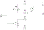
fig. 23a is a schematic view of a first embodiment of a control circuit for an electric motor according to the present invention, when the circuit breaker is in the open state and a closing voltage signal is applied across the first switching element and the closing circuit;
fig. 23b is a schematic view of the first embodiment of the control circuit of the motor of the present invention, when the circuit breaker is in the closed state, and the opening voltage signal is applied across the first switching element and the opening circuit;
fig. 24a is a schematic view of a second embodiment of a control circuit for an electric motor according to the present invention, when the circuit breaker is in an open state, the first switching element turns on the closing circuit, the second switching element turns on the closing auxiliary circuit, and the closing voltage signal is applied across the first switching element and the closing circuit;
fig. 24b is a schematic view of a second embodiment of the control circuit of the motor of the present invention, when the circuit breaker is in a closed state, the first switching element turns on the opening circuit, the second switching element turns on the opening auxiliary circuit, and the opening voltage signal is applied across the first switching element and the opening circuit;
fig. 24c is a schematic view of a second embodiment of the control circuit of the motor of the present invention, when the circuit breaker has been driven to an open state by the manual operating assembly, the first switching element completes the open circuit, the second switching element completes the closing auxiliary circuit, and the closing voltage signal is applied across the first switching element and the closing circuit;
fig. 24d is a schematic view of a second embodiment of the control circuit of the motor of the present invention, when the circuit breaker has been driven to a closed state by the manually operated member, the first switching element completes the closing circuit, the second switching element completes the opening auxiliary circuit, and the opening voltage signal is applied across the first switching element and the opening circuit;
fig. 25a is a schematic view of a third embodiment of the control circuit of the motor of the present invention, when the circuit breaker is in the open state and the closing voltage signal is applied across the first switching element and the closing circuit;
fig. 25b is a schematic view of a third embodiment of the control circuit of the motor of the present invention, when the circuit breaker is in the closed state and the opening voltage signal is applied across the first switching element and the opening circuit;
fig. 26a is a schematic view of a fourth embodiment of a control circuit for an electric motor according to the present invention, when the circuit breaker is in an open state, the first switching element turns on the closing circuit, the second switching element turns on the closing auxiliary circuit, and the closing voltage signal is applied across the first switching element and the closing circuit;
fig. 26b is a schematic diagram of a fourth embodiment of the control circuit of the motor of the present invention, when the circuit breaker is in a closed state, the first switching element turns on the opening circuit, the second switching element turns on the opening auxiliary circuit, and the opening voltage signal is applied across the first switching element and the opening circuit;
fig. 26c is a schematic view of a fourth embodiment of the control circuit of the motor of the present invention, when the circuit breaker has been driven to an open state by the manual operating assembly, the first switching element completes the open circuit, the second switching element completes the closing auxiliary circuit, and the closing voltage signal is applied across the first switching element and the closing circuit;
fig. 26d is a schematic diagram of a fourth embodiment of the control circuit of the motor of the present invention, when the circuit breaker is driven to switch to the closing state by the manual operation assembly, the first switching element turns on the closing circuit, the second switching element turns on the opening auxiliary circuit, and the opening voltage signal is applied to both ends of the first switching element and the opening circuit.
Detailed Description
The following description of the embodiments of the circuit breaker according to the present invention will be made with reference to the embodiments shown in fig. 1 to 26 d. The circuit breaker of the present invention is not limited to the description of the following embodiments.
The invention discloses a circuit breaker, which comprises a circuit breaker shell 1, and a button mechanism 2, an electric mechanism 3 and an operating mechanism 5 which are arranged in the circuit breaker shell 1; the moving contact 1a connected with the operating mechanism 5 and the static contact 1b matched with the moving contact 1a for use; the button mechanism 2 can be operated to drive the circuit breaker to switch on/off through the operating mechanism 5, so that manual switching on/off is realized; the electric mechanism 3 is in driving fit with the button mechanism 2 and/or the operating mechanism 5 to drive the breaker to switch on/off (electric switching-off/switching-on), so that automatic switching-on/off is realized. Further, the circuit breaker of the present invention further includes a short-circuit protection mechanism 6, an arc extinguishing system 7, an overload protection mechanism 110, an incoming terminal 880 and an outgoing terminal 881; the short-circuit protection mechanism 6 and the overload protection mechanism 110 are respectively in driving fit with the operating mechanism 5, and when the breaker has a short-circuit fault or an overload fault, the short-circuit protection mechanism 6 and the overload protection mechanism 110 drive the operating mechanism 5 to trip, so that the moving contact 1a and the static contact 1b of the breaker can be disconnected.
The first circuit breaker disclosed by the invention comprises the following components:
as shown in fig. 1, 9-12, the present invention discloses a circuit breaker, which comprises a circuit breaker housing 1, and a button mechanism 2, an electric mechanism 3, and an operating mechanism 5 arranged in the circuit breaker housing 1; the button mechanism 2 is operated to drive the breaker to close/open through the operating mechanism 5; electric mechanism 3 and button mechanism 2 and 5 drive coordination of operating device, electric mechanism 3 closes a floodgate through 5 drive circuit breakers of operating device, and electric mechanism 3 opens a floodgate through 2 drive circuit breakers of button mechanism. The operating mechanism 5 comprises a transmission piece 501 which is arranged on the breaker shell 1 in a pivoting mode and is connected with the button mechanism 2 in a driving mode, the button mechanism 2 is pressed to drive the transmission piece 501 to rotate towards the closing direction to achieve manual closing, and the button mechanism 2 is pulled to drive the transmission piece 501 to rotate reversely to achieve manual opening; the electric mechanism 3 drives the transmission part 5 to rotate so as to enable the circuit breaker to be switched on (electrically switched on), and the electric mechanism 3 drives the transmission part 501 to rotate reversely through the button mechanism 2 so as to enable the circuit breaker to be switched off (electrically switched off). Further, as shown in fig. 1, 9-12, the electric mechanism 3 includes a driving gear element 305 and a driven gear 306 respectively pivotally disposed on the circuit breaker housing 1, the driving gear element 305 is in driving fit with the driven gear 306, and the driven gear 306 is coaxially disposed with and in driving fit with the transmission member 501; the driving gear piece 305 is in driving fit with the driven gear 306, the driven gear 306 drives the transmission piece 501 to rotate towards the closing direction to enable the circuit breaker to be closed, the driving gear piece 305 is in driving fit with the button mechanism 2, and the button mechanism 2 drives the transmission piece 501 to rotate reversely to enable the circuit breaker to be opened and closed, so that automatic opening and closing are achieved. The circuit breaker comprises an electric mechanism for realizing automatic opening and closing of the circuit breaker, wherein the closing operation is realized by the cooperation of the electric mechanism and an operating mechanism, and the opening operation is realized by the cooperation of the electric mechanism and a button mechanism, so that the structure of the electric opening and closing is simplified, and the service life of the circuit breaker is prolonged.
Further, as one of the improvement points of the present invention, the rotation direction of the driving gear 305 driving the driven gear 306 to realize the closing of the circuit breaker is the same as the rotation direction of the driving button mechanism 2 to realize the opening, that is, in the automatic opening and closing process, the motor of the electric mechanism 3 always rotates in one direction, which is beneficial to simplifying the control process of the electric mechanism 3. In a specific embodiment, during closing, the driving gear 305 rotates from a first initial position to a first direction to be engaged with the driven gear 306, the driving gear 306 continues to rotate and drives the transmission member 501 to rotate through the driven gear 306 to a second direction, so that after the circuit breaker is closed, the driving gear 305 continues to rotate to an intermediate position (the intermediate position refers to a position where the gear 305 is disengaged from the driven gear 306 and the gear 305 does not drive the connecting member 204 in the button mechanism 2) and is disengaged from the driven gear 306; during opening, the driving gear 305 rotates from the middle position to the first direction and drives the button mechanism 2 to act, and the button mechanism 2 drives the transmission member 501 to rotate to the first direction, so that after the circuit breaker is opened, the driving gear 305 continues to rotate to the first initial position (i.e. the manual opening and closing function position of the circuit breaker is not affected). According to the circuit breaker, the switching-on operation is realized through the matching of the electric mechanism 3 and the operating mechanism 5, and the switching-off operation is realized through the matching of the electric mechanism 3 and the button mechanism 2, so that compared with the circuit breaker in which the switching-on/switching-off operation is realized through the matching of the electric mechanism 3 and the operating mechanism 5 in the prior art, the wear progress of the operating mechanism 5 is effectively slowed down, and the service life of the circuit breaker is prolonged; secondly, in the process of switching on/off, the driving gear piece 305 of the electric mechanism 3 always rotates towards the first direction, that is, in the process of switching on/off, the motor 301 of the electric mechanism 3 does not need to change the direction of rotation, which is beneficial to simplifying the control process of the electric mechanism 3; thirdly, the motor 301 of the electric mechanism 3 does not need to be switched between forward rotation and reverse rotation frequently, so that the damage probability of the motor 301 is reduced, and the service life of the electric mechanism 3 is prolonged.
Preferably, as shown in fig. 1, the button mechanism 2 includes a button member 201 and a connecting member 204 slidably disposed on the circuit breaker housing 1, respectively, a first link 202 having two ends connected to the button member 2 and the connecting member 204, respectively, and a second link 203 having two ends connected to the connecting member 204 and the transmission member 501, respectively. It should be noted that the button member 201, the first link 202, and the connecting member 204 of the button mechanism 2 may also be designed as an integral component, thereby reducing the number of parts. In order to facilitate the engagement of the button mechanism 2 with other mechanisms without affecting the engagement with the electric mechanism 3, the button mechanism 2 of the present invention is preferably an assembly of a button member 201, a first link 202, a connecting member 204, and a second link 203. Furthermore, an indicator (not shown in the figure) for indicating the switching on/off state is further arranged in the button member 201, an indication window is arranged on the button member 201, and the button member 201 drives the indicator to swing or slide to display the switching on/off state of the circuit breaker during the switching on/off operation.
Further, as shown in fig. 17, the circuit breaker further includes a locking mechanism 4, one end of the locking mechanism 4 is a locking mechanism driven end protruding outside the circuit breaker housing 1, and the other end is a locking mechanism mating end and is mated with the button mechanism 2. An improvement of the present invention is that the locking mechanism engaging end of the locking mechanism 4 engages with the button member 201 or the first link 202, and the driving gear member 305 of the electric mechanism 3 engages with the connecting member 204; the button mechanism 2 is formed by combining a button member 201, a first link 202 and a connecting member 204, so that the button mechanism 2 can be matched with the locking mechanism 4 and the electric mechanism 3 at the same time. It should be noted that, the circuit breaker of this embodiment is an insertion type circuit breaker, and is inserted into a circuit breaker assembly position installed in a cabinet, and the locking mechanism 4 is matched with the button mechanism 2 and a housing of the circuit breaker assembly position, so as to achieve locking after the circuit breaker is installed in the circuit breaker assembly position, and/or unlocking, and/or preventing the circuit breaker from being installed in a non-position, and/or preventing the circuit breaker from being installed in the circuit breaker assembly position or being pulled out of the circuit breaker assembly position in a closing state, and/or preventing the circuit breaker from being closed when the circuit breaker is not installed in the circuit breaker assembly position.
For example, one embodiment of the locking mechanism is that a locking hole matched with the passive end of the locking mechanism is correspondingly arranged on the circuit breaker assembly position of the cabinet, after the circuit breaker is assembled in place, the passive end of the locking mechanism 4 protrudes out of the circuit breaker shell 1 and into the locking hole of the cabinet, so as to prevent the circuit breaker from being randomly pulled out of the cabinet, and the button 201 is pulled, and the button 201 or the first connecting rod 202 or the connecting piece 204 or the indicating piece can drive the locking mechanism assembly position to retract the passive end of the locking mechanism into the circuit breaker shell 1, so that the circuit breaker can be pulled out of the circuit breaker assembly position. Another embodiment of the locking mechanism is that when the circuit breaker is not installed in the circuit breaker assembly position, the driven end of the locking mechanism is extruded by the cabinet wall to be retracted into the circuit breaker housing 1, and the matching end of the locking mechanism is in limit fit with the button 201, the first connecting rod 202, the connecting member 204 or the indicator, so as to prevent the button 201 from moving in the closing direction and being unable to close when the circuit breaker is not installed in the circuit breaker assembly position; when the circuit breaker is installed in the circuit breaker assembly position, the driven end of the locking mechanism is not pressed by the shell of the circuit breaker assembly position to move towards the outside of the circuit breaker shell 1 any more, so that the matching end of the locking mechanism is released from limit matching with the button 201 or the first connecting rod 202 or the connecting piece 204, and the button 201 can move towards the closing direction and close the circuit breaker through the operating mechanism 5.
Preferably, as shown in fig. 4 and 9-12, the circuit breaker of the present invention further comprises an energy storage spring 3-5 disposed between the driven gear 306 and the transmission member 501; the automatic switching-on compensation device is used for realizing the compensation of the automatic switching-on which is not in place and improving the reliability of the automatic switching-on. The energy storage springs 3-5 are arranged to reserve a certain margin for the matching stroke of the sector gears of the driving gear 305 and the driven gear 306, and to reliably close the switch through the mentioned margin stroke even if matching errors occur between the gears and the structural members due to abrasion. Specifically, the driving gear 305 rotates from the first initial position to the first direction to be meshed with the driven gear 306, the driving gear 305 continues to rotate and drives the driven gear 306 to rotate to the second direction, the driven gear 306 drives the transmission member 501 to rotate to the second direction through the energy storage spring 3-5, after the circuit breaker is closed, the driving gear 305 continues to rotate to the first direction and drives the driven gear 306 to rotate to the second direction relative to the transmission member 501, and the energy storage spring 3-5 stores energy until the driving gear 305 rotates to the middle position and is disengaged from the driven gear 306. According to the circuit breaker, the energy storage spring 3-5 is arranged between the driven gear 306 of the electric mechanism 3 and the transmission piece 501 of the operating mechanism 5, after the circuit breaker is closed, the driving gear piece 305 of the electric mechanism 3 can drive the driven gear 306 to rotate towards the second direction relative to the transmission piece 501, so that the energy storage spring stores energy, the circuit breaker is closed in place, namely, the circuit breaker is effectively closed, and the power utilization safety of a user is improved. Further, as shown in fig. 9 and 12, when the circuit breaker is in a closed state, the driving gear 305 rotates from the middle position to the first direction to drive the button mechanism 2 to operate, and the button mechanism 2 drives the transmission member 501 to rotate to the first direction, so that after the circuit breaker is opened, the driving gear 305 continues to rotate to the first initial position.
The following is a second circuit breaker disclosed by the invention:
as shown in fig. 21, 23a, 23b, 25a and 25b, the circuit breaker of the present invention includes an electric mechanism 3 and an operating mechanism 5 for implementing automatic switching, the electric mechanism 3 and the operating mechanism 5 are in driving fit (including direct and indirect driving fit), the electric mechanism 3 includes a motor 301 and a gear set, the gear set is in driving connection with the motor 301, and the gear set includes a trigger gear; the circuit breaker also comprises a switching device, a closing circuit and an opening circuit; the switching device comprises a first switching element 9B which is in driving fit with the trigger gear, the output end of the first switching element 9B is respectively connected with a switching-on circuit and a switching-off circuit, and the motor 301 is respectively connected in series in the switching-on circuit and the switching-off circuit; when the circuit breaker is in an opening state and the first switch part 9B is connected with a closing circuit and simultaneously is disconnected with the opening circuit, closing voltage signals are loaded at two ends of the first switch part 9B and the closing circuit, and after the electric mechanism 3 drives the circuit breaker to close, the triggering gear drives the first switch part 9B to disconnect the closing circuit and connect the opening circuit; the circuit breaker is in a closing state, the first switch part 9B is connected with the opening circuit and simultaneously disconnected with the closing circuit, opening voltage signals are loaded at two ends of the first switch part 9B and the opening circuit, and after the electric mechanism 3 drives the circuit breaker to open, the triggering gear drives the first switch part 9B to disconnect the opening circuit and connect the closing circuit. After the circuit breaker completes switching on/off operation, the trigger gear drives the first switch part 9B to realize switching on/off of a switching circuit, the control principle is simple, a voltage signal is loaded to the electric mechanism 3, the electric mechanism 3 can act, and after the switching on/off operation is completed, the trigger gear drives the first switch part 9B to switch on/off of the switching circuit, so that a motor can stop running, the complex circuit structure and the control principle for detecting the specific position of the gear in the prior art are not needed, the overall structure of the circuit breaker and the control circuit of the electric mechanism 3 are simplified, and the working performance of the circuit breaker is more reliable. It should be noted that the motor of the present invention is suitable for pure electric switching on and off operation.
The following is a third circuit breaker disclosed by the present invention:
preferably, as shown in fig. 21, 22, 24a-24d, 26a-26d, the circuit breaker of the present invention further includes a manual operating assembly, a closing auxiliary circuit and an opening auxiliary circuit, wherein the manual operating assembly drives the circuit breaker to close/open through the operating mechanism 5; the switching device also comprises a second switching element 9C which is in driving fit with the manual operation assembly or the operation mechanism 5, and the output end of the second switching element 9C is respectively connected with the closing auxiliary circuit and the opening auxiliary circuit; the manual operation assembly is in driving connection with the operation mechanism 5; the switching-on auxiliary circuit and the switching-off auxiliary circuit are respectively connected with two input ends of the motor 301; the input end of the second switch 9C is connected with the input end of the first switch 9B;
when the circuit breaker is in a switching-off state, the first switch part 9B is connected with a switching-on circuit, and the second switch part 9C is connected with a switching-on auxiliary circuit, switching-on voltage signals are loaded at two ends of the first switch part 9B and the switching-on circuit, after the electric mechanism 3 drives the circuit breaker to switch on, the trigger gear drives the first switch part 9B to switch off the switching-on circuit and connect the switching-off circuit, and meanwhile, the action of the manual operation assembly or the operation mechanism 5 during switching-on drives the second switch part 9C to switch off the switching-on auxiliary circuit and connect the switching-off auxiliary circuit;
when the circuit breaker is in a closing state, the first switch part 9B is connected with the opening circuit, and the second switch part 9C is connected with the opening auxiliary circuit, opening voltage signals are loaded at two ends of the first switch part 9B and the opening circuit, after the electric mechanism 3 drives the circuit breaker to open, the trigger gear drives the first switch part 9B to open the opening circuit and connect the closing circuit, and meanwhile, the action of the manual operation assembly or the operation mechanism 5 during opening drives the second switch part 9C to open the opening auxiliary circuit and connect the closing auxiliary circuit;
when the circuit breaker is in a closing state, the first switch part 9B is connected with the opening circuit, the second switch part 9C is connected with the opening auxiliary circuit, and after the circuit breaker is driven to open through the manual operation assembly, the second switch part 9C is driven to disconnect the opening auxiliary circuit and connect the closing auxiliary circuit through the action of the manual operation assembly or the operation mechanism 5 during opening; loading a closing voltage signal at two ends of the first switch part 9B and the opening circuit, wherein the motor 301 drives the trigger gear to rotate, the trigger gear drives the first switch part 9B to open the opening circuit and close the closing circuit, then the electric mechanism 3 drives the breaker to close, the trigger gear drives the first switch part 9B to open the closing circuit and close the opening circuit, and meanwhile, the manual operation assembly or the operation mechanism 5 drives the second switch part 9C to open the closing auxiliary circuit and close the opening auxiliary circuit;
when the circuit breaker is in an opening state, the first switch part 9B is connected with a closing circuit, the second switch part 9C is connected with an auxiliary closing circuit, and after the circuit breaker is driven to be closed by the manual operation assembly, the second switch part 9C is driven to be disconnected with the auxiliary closing circuit and connected with the auxiliary opening circuit by the action of the manual operation assembly or the operation mechanism 5 during closing; the two ends of the first switch part 9B and the closing circuit are loaded with opening voltage signals, the motor 301 drives the trigger gear to rotate, the trigger gear drives the first switch part 9B to break the closing circuit and connect the opening circuit, then the electric mechanism 3 drives the breaker to open, the trigger gear drives the first switch part 9B to break the opening circuit and connect the closing circuit, and meanwhile, the manual operation assembly or the operation mechanism 5 drives the second switch part 9C to break the opening auxiliary circuit and connect the closing auxiliary circuit.
The breaker can normally switch on and off by loading the switching-on voltage signal and the switching-off voltage signal when the current state (namely the switching-off state or the switching-on state) of the breaker is correspondingly consistent and inconsistent with the position of the trigger gear. It should be noted that the condition that "the current state of the circuit breaker is inconsistent with the position of the trigger gear" is caused by that the electric mechanism 3 drives the circuit breaker to open or close through the operating mechanism 5, and then the circuit breaker is opened or closed through the manual operating assembly; if the circuit breaker is driven to be switched on or switched off only by the electric mechanism 3 through the operating mechanism 5, the current state of the circuit breaker is always correspondingly consistent with the position of the trigger gear. Therefore, the circuit breaker can be compatible with manual/automatic switching-on and switching-off operations at the same time through the matching of the trigger gear, the first switch part 9B, the switching-on circuit, the switching-off circuit, the second switch part 9C, the switching-on auxiliary circuit and the switching-off auxiliary circuit.
It should be noted that, the second and third circuit breakers can be implemented on the basis of the first circuit breaker, specifically: the second circuit breaker can be additionally provided with a first switch part 9B, a closing circuit and an opening circuit on the first circuit breaker, and the first switch part 9B is in driving fit with a trigger gear of the electric mechanism 3; the third circuit breaker can be additionally provided with a second switch part 9C, a closing auxiliary circuit and a breaking auxiliary circuit on the basis of the second circuit breaker, and the second switch part 9C is in driving fit with a manual operation assembly or an operation mechanism 5.
As shown in fig. 1 to 20, a first embodiment of the circuit breaker of the present invention is a 1 st embodiment of a first circuit breaker.
As shown in fig. 1 and 9-12, the circuit breaker of the present invention includes a circuit breaker housing 1, and a button mechanism 2, an electric mechanism 3 and an operating mechanism 5 which are arranged in the circuit breaker housing 1, wherein the button mechanism 2 is drivingly connected to the operating mechanism 5, and can drive the circuit breaker to close/open through the operating mechanism 5, so as to implement manual opening/closing; the electric mechanism 3 is in driving fit with the button mechanism 2 and/or the operating mechanism 5, and the circuit breaker is driven to be switched on/off through the operating mechanism 5, so that automatic switching-on/off is realized.
Preferably, as shown in fig. 1, the electric mechanism 3 cooperates with the transmission member 501 of the operating mechanism 5 to realize closing of the circuit breaker, and cooperates with the button mechanism 2 to realize opening of the circuit breaker. The electric mechanism 3 comprises a driving gear piece 305 and a driven gear piece 306 which are respectively and pivotally arranged on the circuit breaker shell 1, and the driving gear piece 305 is respectively in driving fit with the driven gear piece 306 and the button mechanism 2; the operating mechanism 5 comprises a transmission piece 501 which is pivotally arranged on the circuit breaker shell 1 and is in driving connection with the button mechanism 2, and the driven gear 306 and the transmission piece 501 are coaxially arranged and are in driving fit; the driving gear 305 rotates from a first initial position (shown in fig. 9) to a first direction to be meshed with the driven gear 306 (shown in fig. 10), the driving gear 305 continues to rotate and drives the transmission member 501 to rotate in a second direction through the driven gear 306, so that after the circuit breaker is closed, the driving gear 305 continues to rotate to a middle position (shown in fig. 12) and is disengaged from the driven gear 306; the driving gear 305 rotates from the middle position to the first direction to drive the button mechanism 2 to act, and the button mechanism 2 drives the transmission member 5 to rotate to the first direction, so that after the circuit breaker is opened, the driving gear 305 continues to rotate to the first initial position.
The rotation direction of the driving gear 305 driving the driven gear 306 to realize the closing of the circuit breaker is consistent with the rotation direction of the driving button mechanism 2 to realize the opening, which is beneficial to simplifying the control process of the electric mechanism 3. Specifically, as shown in fig. 1 and 9-12, the first direction is a counterclockwise direction, the second direction is a clockwise direction, and the driving gear 305 always keeps rotating in the counterclockwise direction (i.e., always rotates in the same direction) during the closing and opening processes of the circuit breaker; the driving gear member 305 is disengaged from the driven gear 306 when it is in the first initial position or the intermediate position. When the driving gear 305 rotates to the first initial position or the intermediate position, the driving gear 305 or the driven gear 306 triggers to disconnect the power supply circuit of the electric mechanism 3, so that the motor 301 is powered off, the driving gear 305 stops rotating, and the control process of the electric mechanism 3 can be greatly simplified. Of course, when the driving gear 305 rotates to the first initial position or the intermediate position, the driving gear 305 or the driven gear 306 triggers the position sensor to transmit the position information to the control chip, and the control chip controls the motor to stop rotating.
Preferably, the driven gear 306 and the transmission member 501 are an integral member or a split member.
Preferably, the electric mechanism 3 comprises an electric motor 301 and a gear set which are connected in a driving manner, and the gear set comprises a transmission gear set, a driving gear piece 305 and a driven gear 306. As shown in fig. 1, is an embodiment of the electric mechanism 3. The electric mechanism 3 comprises a motor 301, a worm 302, a first transmission gear 303, a second transmission gear 304 and a driving gear 305 which are in driving fit in sequence, and a driven gear 306 which is in driving fit with the driving gear 305; the transmission gear set comprises the first transmission gear piece 303 and the second transmission gear piece 304, and the first transmission gear piece 303, the second transmission gear piece 304 and the driving gear piece 305 are respectively and pivotally arranged on the circuit breaker shell 1. Obviously, the number of drive gear members of the drive gear set may be reduced or increased as desired.
Preferably, as shown in FIG. 3, the driving gear member 305 includes a first driving gear 305-1 and a driving gear 305-20 in driving engagement with the driven gear 306 and the button mechanism 2, respectively. Specifically, the driving gear piece 305 comprises a first driving gear 305-1, a second driving gear 305-2 and a third driving gear 305-3 which are coaxially linked and sequentially arranged, the third driving gear 305-3 is in driving fit with a second driving gear piece 304 of the driving gear set, and the first driving gear 305-1 and the second driving gear 305-2 are respectively in driving fit with the driven gear 306 and the button mechanism 2; further, as shown in fig. 1 and 4, the first driving gear 305-1 and the driven gear 306 are both sector gears; the second driving gear 305-2 is provided with driving teeth 305-20 which are in driving engagement with the button mechanism 2. When the switch is switched on, the driving gear piece 305 rotates towards a first direction, the first driving gear 305-1 is meshed with the driven gear 306, the driving gear 305-20 is avoided from the button mechanism 2, and the first driving gear 305-1 is disengaged from the driven gear 306 after the switch is switched on; during brake opening, the driving gear piece 305 continues to rotate towards the first direction, the driving gear 305-20 is in driving fit with the button mechanism 2 to realize brake opening, and at the moment, the first driving gear 305-1 and the driven gear 306 are kept in a disengaged state. Obviously, the drive teeth 305-20 may be a sector gear comprising only one drive tooth 305-20 as shown in fig. 3, or may be provided as a plurality of drive teeth as desired, and the coupling member 204 on the button mechanism 2 may be provided with teeth to cooperate with the second drive gear 305-2 having a plurality of drive teeth. In addition, drive teeth 305-20 may also be provided on first drive gear 305-1.
Preferably, as shown in fig. 1, the button mechanism 2 includes a button member 201 and a connecting member 204 slidably disposed on the circuit breaker housing 1, respectively, a first link 202 having two ends connected to the button member 201 and the connecting member 204, respectively, and a second link 203 having two ends connected to the connecting member 204 and the transmission member 501, respectively; the button 201 is pressed/pulled, and the transmission member 501 is driven to rotate towards the second direction/the first direction through the first connecting rod 202, the connecting member 204 and the second connecting rod 203 which are connected in sequence, so that the circuit breaker is switched on/off. Further, as shown in FIG. 1, a second drive gear 305-2 of the drive gear member 305 is in driving engagement with the connecting member 204.
Specifically, as shown in fig. 1 and 9-12, the button 201, the first link 202, the connecting member 204, and the second link 203 of the button mechanism 2 are sequentially linearly arranged from top to bottom, the button 201 is pulled upward/pressed downward, and the button 201 drives the transmission member 501 to rotate counterclockwise/clockwise through the first link 202, the connecting member 204, and the second link 203 which are sequentially connected, so as to close/open the circuit breaker; when the circuit breaker is in a closing state, the second driving gear 305-2 drives the connecting element 204 to move upwards, and the connecting element 204 drives the transmission element 501 to rotate clockwise through the second connecting rod 203, so that the circuit breaker is opened.
Preferably, as shown in fig. 17, the circuit breaker of the present invention further includes a locking mechanism 4, one end of the locking mechanism 4 is a locking mechanism driven end protruding outside the circuit breaker housing 1, and the other end is a locking mechanism mating end, and is in limit fit with the button mechanism 2. The locking mechanism 4 comprises a locking piece with the middle part pivotally arranged on the shell 1 of the circuit breaker, and the two ends of the locking piece are respectively a locking mechanism driven end and a locking mechanism matching end. Specifically, as shown in fig. 17, the upper end and the lower end of the locking element of the locking mechanism 4 are respectively a locking mechanism driven end and a locking mechanism mating end, and when the button 201 or the first connecting rod 202 is in limit fit with the locking mechanism mating end, the button 201 cannot move downward (in the closing direction), and the circuit breaker cannot be closed.
Preferably, the first link 202 and the second link 203 are both U-shaped links.
Preferably, as shown in fig. 1, the button mechanism 2 further includes a first return spring 205 for returning the driving link 204, so as to drive the button mechanism 2 to return after the circuit breaker is tripped; the circuit breaker housing 1 further includes a connector rail groove, and the connector 204 linearly slides along the connector rail groove.
Preferably, as shown in fig. 2, is one embodiment of the connection member 204.
As shown in FIG. 2, the connecting member 204 is a strip-shaped member, and includes a connecting member main body 204-0, a connecting member first hole 204-1 and a connecting member second hole 204-3 respectively disposed at both ends of the connecting member main body 204-0 and respectively engaged with the first connecting rod 202 and the second connecting rod 203, a connecting member driven table 204-4 engaged with the driving teeth 305-20 of the driving gear member 305, a connecting member spring limit boss 204-2 disposed at one side of the connecting member main body 204-0, and a connecting member rail boss 204-5 disposed on the connecting member main body 204-0. Further, as shown in fig. 2, the connector rail boss 204-5 and the connector first hole 204-1 are disposed at the same end of the connector main body 204-0, and the connector rail boss 204-5 is disposed at a side of the connector main body 204-0 facing the bottom plate of the circuit breaker housing 1; the connecting piece driven table-board 204-4 and the connecting piece second hole 204-3 are arranged at the same end of the connecting piece main body 204-0, and the connecting piece driven table-board 204-4 is arranged facing the transmission piece 501 of the operating mechanism 5; the connecting piece spring limiting boss 204-2 is arranged on one side of the connecting piece main body 204-0 far away from the electric mechanism 3.
Specifically, as shown in the orientation of FIG. 2, the connector first hole 204-1 and the connector track boss 204-5 are located at the left end of the connector body 204-0, and the connector track boss 204-5 is located at the lower side of the connector body 204-0; the second hole 204-3 of the connecting piece and the driven table-board 204-4 of the connecting piece are positioned at the right end of the main body 204-0 of the connecting piece, and the driven table-board 204-4 of the connecting piece is arranged facing to the right side; the connector spring limiting boss 204-2 is arranged on the rear side of the connector main body 204-0.
As shown in fig. 1, the first return spring 205 is disposed between the connector spring limit boss 204-2 and the circuit breaker case 1; the connector track boss 204-5 is slidably disposed in the connector track groove. The effective limit between the connecting piece 204 and the circuit breaker shell 1 is formed by the matching of the connecting piece track boss 204-5 and the connecting piece track groove, so that the stability of the sliding process of the connecting piece 204 is ensured, and the stability of the circuit breaker performance is improved. Further, as shown in fig. 17, the locking member 4 and the first return spring 205 are located on the same side of the button member 201 and the connecting member 204. Specifically, as shown in fig. 17, the locking member 4 and the first return spring 205 are located on the right side of the button member 201 and the connecting member 204.
Preferably, as shown in fig. 1, one end of the button 201 is an operation end located outside the circuit breaker housing 1, the other end of the button extends into the circuit breaker housing 1, and a button connection hole for installing the first link 202 is formed in the other end of the button, and the button connection hole is a long-strip-shaped waist-shaped hole, so that the button 201 is pressed to enable one end to have an idle stroke, and when the circuit breaker after opening is required to be pulled out from the installation cabinet, the button 201 of the button mechanism 2 is pulled, so that the locking mechanism 4 is completely retracted into the circuit breaker housing, and the circuit breaker is pulled out from the circuit breaker installation position by contacting the limit fit of the locking mechanism 4 and the housing of the circuit breaker installation position.
Preferably, as shown in fig. 1, is an embodiment of the operating mechanism 5.
As shown in fig. 1, the operating mechanism 5 includes a driving member 501 and a rotating plate 505 pivotally provided on the circuit breaker housing 1, respectively, a trip 503 and a latch 504 pivotally provided on the rotating plate 505 and snap-engaged with each other, respectively, a third link 502 having both ends connected to the driving member 501 and the trip 503, respectively, and a second return spring 506 for driving the rotating plate 504, the second return spring 50 being provided between the latch 504 and the circuit breaker housing 1. The circuit breaker further comprises a fixed contact 1b and a movable contact 1a connected with the operating mechanism 5, one end of the movable contact 1a is connected with the rotating plate 505, and the fixed contact 1b is fixedly arranged on the circuit breaker shell 1. The structure, principle and operation process of the operating mechanism 5 of the present embodiment are similar to those of the prior art, and are not described in detail herein. Of course, the operating mechanism 5 of the circuit breaker of the present invention may also take other configurations.
Preferably, as shown in fig. 4-8, the second embodiment of the circuit breaker of the present invention is the 2 nd embodiment of the first circuit breaker.
As shown in fig. 4, the present embodiment is different from the circuit breaker of the first embodiment in that: the energy storage spring 3-5 is arranged between the driven gear 306 and the transmission piece 501; the automatic switching-on compensation device is used for realizing the compensation of the automatic switching-on which is not in place and improving the reliability of the automatic switching-on. The energy storage springs 3-5 are arranged to reserve a certain margin for the matching stroke of the sector gears of the driving gear piece 305 and the driven gear 306, and to reliably close the switch even if the gears are worn and have matching errors. Specifically, the driving gear 305 rotates from the first initial position to the first direction to be meshed with the driven gear 306, the driving gear 305 continues to rotate and drives the driven gear 306 to rotate to the second direction, the driven gear 306 drives the transmission member 501 to rotate to the second direction through the energy storage spring 3-5, after the circuit breaker is closed, the driving gear element 305 continues to rotate towards the first direction and drives the driven gear 306 to rotate towards the second direction relative to the transmission element 501, so that the energy storage springs 3-5 store energy and enable the moving and fixed contacts to be reliably contacted until the driving gear element 305 rotates to the middle position and is disengaged from the driven gear 306, and the driven gear 306 resets relative to the transmission element 501 under the action of the energy released by the energy storage springs 3-5 (the energy storage springs 3-5 release energy and give a force to the driven gear 306 to enable the driven gear 306 to rotate towards the first direction relative to the transmission element 501).
Preferably, as shown in fig. 4 and 8, the energy storage spring 3-5 is a torsion spring, and includes a spring main body 3-50, a first spring arm 3-51 and a second spring arm 3-52; the spring main bodies 3-50 are arranged between the driven gear 306 and the transmission piece 501 and are coaxially arranged with the driven gear 306 and the transmission piece 501, the first spring arms 3-51 are in limit fit with the transmission piece 501, and the second spring arms 3-52 are in limit fit with the driven gear 306. Further, as shown in fig. 4-7, the transmission member 51 includes a driven gear limiting groove 501 and 306 disposed on one side thereof, the driven gear 306 includes a driven gear body 306-2 and a first sector gear portion 306-1 disposed on one side of the driven gear body 306-2, the driven gear body 306-2 and the transmission member 501 are coaxially and pivotally disposed on the circuit breaker housing 1, the first sector gear portion 306-1 is disposed in the driven gear limiting groove 501 and 306, one end of the first sector gear portion 306-1 abuts against a side wall of one end of the driven gear limiting groove 501 and 306, and a first movement gap is disposed between the other end of the first sector gear portion 306-1 and a side wall of the other end of the driven gear limiting groove 501 and 306; the spring body 3-50 is located between the driven gear body 306-2 and the transmission member 51.
Preferably, as shown in fig. 4-7, the first sector gear portion 306-1 includes a first sector gear portion head end surface 306-10 and a first sector gear portion tail end surface 306-11 respectively disposed at two ends thereof, the transmission member 501 further includes a driven gear limiting groove head end surface 501-6 and a driven gear limiting groove tail end surface 501-4 disposed at two ends of the driven gear limiting groove 501-306, the first sector gear portion head end surface 306-10 abuts against the driven gear limiting groove head end surface 501-6, and a first motion gap is disposed between the first sector gear portion tail end surface 306-11 and the driven gear limiting groove tail end surface 501-4.
Specifically, as shown in fig. 4, when the circuit breaker is in a closing state or an opening state, the energy storage spring 3-5 causes the first sector gear head end face 306-10 of the driven gear 306 to abut against the driven gear slot head end face 501-6, and a first movement gap is formed between the first sector gear part tail end face 306-11 and the driven gear limiting slot tail end face 501-4; as shown in fig. 9-12, the driving gear 305 rotates in a first direction (counterclockwise direction) to mesh with the first sector gear portion 306-1 of the driven gear 306 (as shown in fig. 10), the driving gear 305 continues to rotate and drives the driven gear 306 to rotate in a second direction (clockwise direction) through the first sector gear portion 306-1, the driven gear 306 drives the transmission member 501 to rotate in the second direction (clockwise direction) through the energy storage spring 3-5, the mechanism 5 to be operated drives the movable contact 1a and the fixed contact 1b to close (as shown in fig. 11), after the circuit breaker, the transmission member 501 is fixed in position and does not rotate, as shown in fig. 11, at this time, the driving gear 305 still meshes with the first sector gear portion 306-1, preferably, the difference 1 irregular tooth is set to disengage from meshing, the driving gear 305 continues to rotate and drives the driven gear 306 to close relative to the transmission member 501 through the first sector gear portion 306-1, and drives the driven gear 306 to rotate towards the second direction The energy storage spring 3-5 stores energy by rotating in a direction (clockwise direction), and the energy storage spring 3-5 applies the stored energy to the transmission member 501 (i.e. applies a pushing force to the transmission member 501 to rotate in the first direction), so as to ensure that the circuit breaker can still be effectively closed because of the size deviation of the structural member or because of the gear abrasion of the motor mechanism, as shown in fig. 12, after the circuit breaker is closed, the driving gear member 305 continues to rotate to the middle position and is disengaged from the first sector gear portion 306-1, and the driven gear 306 can be reset under the energy release action of the energy storage spring 3-5 (i.e. the first sector gear portion head end face 306-10 is restored to the state of being abutted against the driven gear limiting groove head end face 501-6).
Preferably, as shown in fig. 4, the driven gear 306 further includes a driven gear spring limiting hole 306-3 disposed on the driven gear body 306-2, the transmission member 501 further includes a transmission member spring limiting groove 501-5 disposed at one end of the driven gear limiting groove 501-306, and the transmission member spring limiting groove 501-5 and the driven gear limiting groove rear end face 501-4 are located at the same end of the transmission gear limiting groove 501-306; the first spring arms 3-51 are in limit fit with the transmission piece spring limiting grooves 501-5, and the second spring arms 3-52 are in limit fit with the driven gear spring limiting holes 306-3.
Preferably, as shown in fig. 4-7, the transmission member 501 further comprises a transmission member main body 501-0 and a transmission member spring installation groove 501-7 disposed on one side of the transmission member main body 501-0, and the driven gear limiting groove 501 and 306 are disposed on one side of the transmission member spring installation groove 501-7; the driven gear body 306-2 and the first sector gear portion 306-1 are arranged in a staggered manner, and the first sector gear portion 306-1 is offset to the side of the transmission member 501 relative to the driven gear body 306-2; the spring main bodies 3-50 are arranged in the transmission piece spring assembly grooves 501-7 and limited between the driven gear body 306-2 and the transmission piece main body 501-0.
Preferably, as shown in fig. 6 and 7, is an embodiment of said transmission member 501.
As shown in FIGS. 6 and 7, the transmission member 501 is a cylindrical structure, and includes a transmission member body 501-0, a transmission member spring assembling groove 501-7 and a driven gear limiting groove 501-306 disposed on one side of the transmission member body 501-0, and a transmission member shaft hole 501-3, a first transmission member connecting hole 501-1 and a second transmission member connecting hole 501-2 disposed on the transmission member body 501-0, respectively; the transmission member spring assembly groove 501-7 and the driven gear limiting groove 501-306 are positioned on the same side of the transmission member body 501-0, and the driven gear limiting groove 501-306 is arranged on one side of the transmission member spring assembly groove 501-7; the transmission piece shaft hole 501-3, the first transmission piece connecting hole 501-1 and the second transmission piece connecting hole 501-2 are positioned at three vertex points of a triangle, the first transmission piece connecting hole 501-1 is arranged close to the driven gear limiting groove 501-306, the transmission piece 501 is pivoted through the transmission piece shaft hole 501-3, the first transmission piece connecting hole 501-1 is connected with the second connecting rod 203 of the button mechanism 2, and the second transmission piece connecting hole 501-2 is connected with the third connecting rod 502 of the operating mechanism 5.
Preferably, as shown in fig. 7 and 13, the transmission member 501 further comprises a stroke limiting groove 501-8, and the stroke limiting groove 501-8 and the driven gear limiting groove 501-306 are respectively disposed on two sides of the transmission member spring assembling groove 501-7; the circuit breaker housing 1 further comprises a positioning stop 102 arranged on one side of the transmission member 501; when the circuit breaker is in an opening state, the side wall of one end of the stroke limiting groove 510-8 is in limiting fit with the in-place stop table 102, and when the circuit breaker is in a closing state, the side wall of the other end of the stroke limiting groove 510-8 is in limiting fit with the in-place stop table 102. Further, as shown in fig. 13, when the circuit breaker is switched on, one end of the stroke limiting groove 501-8 (the lower end of the stroke limiting groove 501-8 in the direction shown in fig. 13) is in limit fit with the in-place block 102, and when the circuit breaker is switched off, the other end of the stroke limiting groove 501-8 (the upper end of the stroke limiting groove 501-8 in the direction shown in fig. 13) is in limit fit with the in-place block 102. The stroke limiting groove 510-8 is in limit fit with the in-place stop table 102, so that effective limit is formed on the rotation stroke of the transmission member 501, and the situation that the transmission member 501 rotates excessively to damage the operating mechanism 5 is avoided.
Preferably, as shown in fig. 4 and 5, is one embodiment of the driven gear 306.
As shown in fig. 4 and 5, the driven gear 306 includes a driven gear body 306-2, a first sector gear portion 306-1, and a driven gear shaft hole 306-4 and a driven gear spring limiting hole 306-3 respectively disposed on the driven gear body 306-2; the driven gear body 306-2 comprises a body base plate 306-20, a body limiting table 306-21 and a body spring limiting table 306-22 which are coaxially arranged in sequence and have diameters which are reduced in sequence, the body base plate 306-20 is abutted against one side of the transmission piece body 501-0 of the transmission piece 501, the body limiting table 306-21 is inserted into a transmission piece spring assembling groove 501-7 of the transmission piece 501, and the body spring limiting table 306-22 is inserted into the middle of a spring main body 3-50 of the energy storage spring 3-5; one end of the first fan-shaped gear part 306-1 is connected with one side of the body substrate 306-20 connected with the body limit table 306-21 and the outer peripheral edge of the body limit table 306-21 respectively. Further, as shown in fig. 4 and 5, the driven gear spring stopper hole 306-3 is located between the driven gear shaft hole 306-4 and the first sector gear portion 306-1.
Preferably, as shown in fig. 14-16, the third embodiment of the circuit breaker of the present invention is the 3 rd embodiment of the first circuit breaker.
As shown in fig. 14 to 16, the present embodiment is different from the circuit breaker of the first embodiment in that: the circuit breaker further comprises a manual-automatic switching device arranged in the circuit breaker housing 1. The circuit breaker is a plug-in circuit breaker, the circuit breaker shell 1 is basically of a parallelepiped structure and comprises a circuit breaker operation interface 1i arranged at one end of the circuit breaker operation interface 1i, and a button assembly hole and an outgoing line terminal 881 which are arranged on the circuit breaker operation interface 1i, one end of the button mechanism 2 is inserted into the button assembly hole, and the other end of the circuit breaker shell 1 is provided with an incoming line terminal 880; the circuit breaker further comprises a manual-automatic switching device arranged in the circuit breaker shell 1, the manual-automatic switching device comprises a switching operation element 7a and a switching switch element 9A, the switching operation element 7a is in driving fit with the switching switch element 9A, the switching switch element 9A is used for realizing switching of the circuit breaker between a manual working mode and an automatic working mode, and the automatic working mode of the circuit breaker is enabled or closed by controlling the working state of the electric mechanism 3; the switching operation element 7a is arranged on the circuit breaker operation interface 1i, is positioned on one side of the button assembly hole and is movably connected with the circuit breaker shell 1. The manual and automatic switching device of the circuit breaker comprises the switching operation element 7a and the switching switch element 9A which are matched in a driving mode, and the circuit breaker is simple in structure and convenient to operate; the switching operation element 7a, one end of the button mechanism 2 and the outlet terminal 881 are all located on the circuit breaker operation interface 1i, the operation space is large, a user can operate the circuit breaker conveniently, and the observation is easy.
Further, as shown in fig. 14-16, the manual-automatic switching device further includes a switching transmission element 8a, and the switching operation element 7a drives the switching element 9A to operate through the switching transmission element 8 a; the switching operation element 7a is a knob rotatably arranged on the circuit breaker housing 1, and comprises a knob connecting part 70a, and a knob operation end 71a and a knob driving part 72a which are respectively arranged at two sides of the knob connecting part 70 a; the change-over switch element 9A is a microswitch, one end of the change-over transmission element 8a is in driving connection with the knob driving part 72a, and the other end is in driving fit with the change-over switch element 9A; the knob is screwed to drive the switching transmission element 8a to move towards or away from the direction of the switching element 9A, and the driving rod of the microswitch is pressed or released.
Further, as shown in fig. 16, the knob driving portion 720a includes a knob driving inclined surface 720a which is in driving engagement with the switching transmission member 8a, and the knob driving inclined surface 720 is gradually shifted toward the switching transmission member 8a from one end thereof near the knob connecting portion 70a to the other end thereof. All parts of the manual-automatic switching device adopt a mechanical transmission mode, the transmission is reliable, and the structure is simple and convenient to assemble.
It should be noted that there are two operating states of the electric machine 3, which are: a normal working state and a disengaged working state; in the automatic working mode, the electric mechanism 3 is in a normal working state, a power supply circuit of the electric mechanism 3 is continuous, and/or the electric mechanism 3 can normally receive a closing/opening signal and can perform manual opening and closing and automatic opening and closing; in the manual working mode, the electric mechanism 3 is in a separation working state, a power supply circuit of the electric mechanism 3 is cut off, and/or the electric mechanism 3 cannot receive a closing/opening signal and can only be manually opened and closed.
Preferably, the change-over switch element 9a is connected in series in the power supply circuit of the electric mechanism 3, and by turning off or on the change-over switch element 9a, the power supply circuit of the electric mechanism 3 can be turned off or on, so that the circuit breaker can be switched between a manual operation mode, i.e., only a manual switching-on/off state, which cannot be automatically switched on/off (the power supply circuit of the electric mechanism 3 is turned off), and an automatic operation mode, i.e., an automatic operation mode, which is enabled, and simultaneously, the manual switching-on/off state and the automatic switching-on/off state (the power supply circuit of the electric mechanism 3 is turned.
Preferably, the circuit breaker further comprises a circuit board 111 connected to the electric mechanism 3, the switch element 9a is disposed on the circuit board 111 and connected to a power control system of the electric mechanism 3 through the circuit board 111, and the power control system cuts off or connects the operating power of the electric mechanism 3 through the switch element 9a, so as to switch the circuit breaker between the manual operating mode and the automatic operating mode.
In addition, the switch element 9A can be connected to a control chip for transmitting a switching control signal, the control chip can switch the circuit breaker between the manual operating mode and the automatic operating mode according to the high/low level of the switching control signal, and when the circuit breaker is in the manual operating mode, the control chip does not control the electric mechanism to perform the automatic closing operation even if the control chip receives the automatic closing control signal.
Preferably, as shown in fig. 15, the outlet terminal 881 is a plug wire type connecting terminal, the circuit breaker housing 1 further includes an outlet hole 1o and a wire-removing hole 1d of the outlet terminal 881 disposed on the circuit breaker operation interface 1i, the outlet hole 1o and the wire-removing hole 1d are used in a one-to-one matching manner, a wire is inserted through the outlet hole 1o and connected with the outlet terminal 881, and is clamped and fixed by an elastic member in the outlet terminal 881, the outlet hole 1o is used for driving the elastic member to enable the wire to be removed, the outlet hole 1o, the wire-removing hole 1d and the switching operation element 7a are all located on the same side of the button assembly hole, and the switching operation element 7a is located between one wire-removing hole 1d and the button assembly hole. Further, as shown in fig. 15, the circuit breaker housing 1 includes two wire holes 1o and two wire detaching holes 1d, which are respectively a first wire hole and a first wire detaching hole for use in cooperation, and a second wire hole and a second wire detaching hole for use in cooperation, the first wire detaching hole and the second wire hole are disposed near the button assembling hole, and the switching operation element 7a is located in a space surrounded by the first wire detaching hole, the second wire hole and the button assembling hole. Further, as shown in fig. 15, the first outlet hole, the first wire-detaching hole and the switching operation element 7a are sequentially arranged side by side on one side of the circuit breaker operation interface 1i, and the second wire-detaching hole and the second outlet hole are sequentially arranged side by side on the other side of the circuit breaker operation interface 1 i.
Specifically, as shown in the orientations of fig. 14 and 16, the upper end of the switching transmission member 8a is in driving engagement with the switching operation member 7a, and the lower end is in driving engagement with the switching switch member 9 a; the switching operation element 7a is screwed to drive the switching transmission element 8a to move downwards, and the switching transmission element 8a is pressed against a driving rod of a microswitch (a switching switch element 9a) to realize signal switching, so that the circuit breaker is driven to switch between a manual working mode and an automatic working mode; the first wire outlet hole, the first wire detaching hole and the switching operation element 7a are sequentially arranged on the upper side of the circuit breaker operation interface 1i side by side from left to right, and the second wire detaching hole and the second wire outlet hole are sequentially arranged on the lower side of the circuit breaker operation interface 1i side by side from left to right.
It should be noted that the switching operation member 7a is not limited to a knob, but may be a button or a slide paddle. Specifically, the switching operation element 7a is a button, and by pressing/pulling the button, the switching transmission element 8a is driven to move towards or away from the switching element 9a, and the switching element 8a triggers or releases the switching element 9 a; alternatively, the switching operation element 7a is a sliding paddle, and is slidably disposed on the circuit breaker operation interface 1i of the circuit breaker housing 1, and the switching transmission element 8a is driven to move towards or away from the switching switch element 9a by sliding the sliding paddle, so that the switching switch element 8a triggers or releases the switching switch element 9 a.
Preferably, as shown in fig. 16, the knob driving portion 72a includes a knob driving inclined surface 720a which is in driving engagement with the switch transmission member 8a, and the knob driving inclined surface 720a is gradually inclined from the end thereof connected to the knob connecting portion 70a toward the end of the knob driving inclined surface 720a adjacent to the switch member 9 a. Further, the knob driving inclined surface 720a is a spiral inclined surface inclined from the upper end to the lower end.
It should be noted that the knob driving portion 72a may not be provided with the knob driving inclined surface 720a, but may be screwed with the switch transmission member 8a, the switch transmission member 8a cannot rotate, the knob is screwed, and the switch transmission member 8a may be driven to move toward or away from the switch member 9 a. Of course, there are other various implementations of the switching operation element 7a as long as the switching transmission element 8a can be driven to move towards or away from the switching switch element 9a, and the description is omitted here.
Preferably, as shown in fig. 14 and 16, the manual-automatic switching apparatus further includes a transmission member return spring 10 for returning the switching transmission member 8 a.
Preferably, as shown in fig. 16, is an embodiment of the shift transmission element 8 a.
As shown in fig. 16, the switching transmission element 8a is a rod-shaped member, and includes a transmission element passive portion 80a, a transmission element spring limiting table 82a and a transmission element transmission portion 81a, which are connected in sequence, the transmission element passive portion 80a is in driving fit with the knob driving portion 720a, and the transmission element transmission portion 81a is in driving fit with the switching switch element 9A. Further, as shown in fig. 14 and 16, the transmission element return spring 10 is sleeved on the transmission element transmission portion 81a, one end of the transmission element return spring is in limit fit with the transmission element spring limit table 82a, and the other end of the transmission element return spring is in limit fit with the circuit breaker housing 1.
Preferably, as shown in fig. 14, the circuit breaker housing 1 further includes a transmission element assembly groove disposed on one side of the button mechanism 2, the transmission element assembly groove includes an assembly groove upper section 103-1, an assembly groove lower section 103-2 and an assembly groove tail section which are connected in sequence, the width of the assembly groove lower section 103-2 is greater than the width of the assembly groove upper section 103-1 and the width of the assembly groove lower section 103-2 is greater than the width of the assembly groove tail section, a first step structure is formed at the junction of the assembly groove lower section 103-2 and the assembly groove upper section 103-1, a second step structure is formed at the junction of the assembly groove lower section 103-2 and the assembly groove tail section, the transmission element driven section 80a is disposed in the middle of the assembly groove upper section 103-1, the transmission element transmission section 81a is disposed in the middle of the assembly groove lower section 103-2, the transmission element spring limit platform 82a is in limit fit with the first step structure, the transmission element return spring 10 is arranged in the middle of the lower section 103-2 of the assembly groove, one end of the transmission element return spring is in limit fit with the transmission element spring limit table 82a, the other end of the transmission element return spring is in limit fit with the second step structure, and the free end of the transmission part 81a of the transmission element penetrates through the tail section of the assembly groove and then is in limit fit with the change-over switch element 9A.
Specifically, as shown in fig. 14, the assembly groove upper section 103-1, the assembly groove lower section 103-2 and the assembly groove tail section are sequentially arranged from top to bottom and are sequentially connected; the transmission element mounting slot is located entirely between the button mechanism 2 and the outlet terminal 881.
In the present embodiment, the electric mechanism 3 directly drives the circuit breaker to close through the operating mechanism, and drives the circuit breaker to open through the button mechanism 2, as another embodiment, the electric mechanism 3 may also directly drive the circuit breaker to open and/or close through the operating mechanism, and drive the circuit breaker to open and/or close through the button mechanism 2, and both are applicable to the manual/automatic switching apparatus of the present invention.
Preferably, as shown in fig. 1, 17-20, the fourth embodiment of the circuit breaker of the present invention is the 4 th embodiment of the first circuit breaker.
Preferably, as shown in fig. 1, 17 and 18, the circuit breaker includes a circuit breaker housing 1, and a button mechanism 2, an electric mechanism 3, an operating mechanism 5, a protection mechanism, an arc extinguishing system 7, a current sampling device 112, an incoming terminal 880 and an outgoing terminal 881 which are arranged in the circuit breaker housing 1; the button mechanism 2 drives the breaker to switch on/off through the operating mechanism 5; the electric mechanism 3 drives the breaker to switch on/off through the button mechanism 2 and/or the operating mechanism 5; the protection mechanism is matched with the operating mechanism 5 to trigger the circuit breaker to trip; the inlet terminal 880 and the outlet terminal 881 are respectively arranged at two ends of the breaker shell 1; the operating mechanism 5 is arranged in the middle of the breaker shell 1; the arc extinguishing system 7 and the protection mechanism are arranged between the operating mechanism 5 and the wire inlet terminal 880 in parallel; the electric mechanism 3 is arranged between the outlet terminal 881 and the operating mechanism 5, and the electric mechanism 3 and the outlet terminal 881 are arranged on the same side of the button mechanism 2; one end of the button mechanism 2 protrudes out of one end of the breaker shell 1 provided with the outlet terminal 881; the current sampling device 112 is disposed between the protection mechanism and the wire inlet terminal 880, and two ends of the sampling device 112 are electrically connected to the protection mechanism and the wire inlet terminal 880, respectively. The circuit breaker has reasonable internal layout design and compact layout among all parts, can effectively reduce the overall specification of the circuit breaker, and conforms to the miniaturization development trend of the circuit breaker; moreover, the current sampling device 112 is arranged between the overload protection mechanism 110 or the short-circuit protection mechanism 6 arranged in parallel with the arc extinguishing system 7 and the wire inlet terminal 880, so that the safety of the current sampling device 112 is remarkably improved, and the signal of the current sampling device 112 is conveniently led out.
Preferably, the protection mechanism is a short-circuit protection mechanism 6 or an overload protection mechanism 110; when the circuit breaker simultaneously comprises the short-circuit protection mechanism 6 and the overload protection mechanism 110, the protection mechanism is the short-circuit protection mechanism 6, the arc extinguishing system 7 and the short-circuit protection mechanism 6 are arranged side by side, the operating mechanism 5 and the overload protection mechanism 110 are arranged side by side in the middle of the shell 1 of the circuit breaker, and the sampling device 112 is arranged between the short-circuit protection mechanism 6 and the wire inlet terminal 880; alternatively, the protection mechanism is the overload protection mechanism 110, the arc extinguishing system 7 and the overload protection mechanism 110 are arranged side by side, the operating mechanism 5 and the short-circuit protection mechanism 6 are arranged side by side in the middle of the circuit breaker housing 1, and the sampling device 112 is arranged between the overload protection mechanism 110 and the incoming line terminal 880.
Preferably, as shown in fig. 17, in the preferred embodiment, the operating mechanism 5 and the overload protection mechanism 110 are arranged side by side in the middle of the circuit breaker housing 1, the arc extinguishing system 7 and the short-circuit protection mechanism 6 are arranged side by side, the overload protection mechanism 110 and the arc extinguishing system 7 are located on one side of the circuit breaker housing 1, and the operating mechanism 5 and the short-circuit protection mechanism 6 are located on the other side of the circuit breaker housing 1; the current sampling device 112 is arranged between the short-circuit protection mechanism 6 and the line inlet terminal 880, the line inlet terminal 880 comprises an L-pole line inlet terminal, and the current sampling device 112 is connected in series between the short-circuit protection mechanism 6 and the L-pole line inlet terminal. Further, as shown in fig. 17, the circuit breaker housing 1 further includes a sampling device mounting groove 112a, and two ends of the sampling device mounting groove 112a are respectively opposite to the L-pole incoming line terminal and the short-circuit protection mechanism 6.
Particularly, the short-circuit protection mechanism 6 of the present invention comprises an electromagnetic trip mechanism, when a short-circuit large circuit occurs, electromagnetic force is increased to trigger the operating mechanism 5 to trip, the overload protection mechanism 110 comprises a bimetallic strip, when overload occurs, the bimetallic strip bends to trigger the latch of the operating mechanism 5 to release the snap-fit between the latch and the jump latch, so that the operating mechanism 5 trips, no chip detection is required, the chip is prevented from being interfered by the outside, and reliable protection is realized. However, in order to realize the current monitoring, the corresponding current sampling device 112 is arranged and can be output to external monitoring equipment, and the current sampling device 112 is arranged in the area far away from the core part of the circuit breaker, so that the influence on the core part of the circuit breaker is avoided, and the safety and reliability of the current sampling device 112 are obviously improved.
Further, as shown in fig. 17 and 18, the circuit breaker of the present invention further includes a circuit board 111 connected to the electric mechanism 3, the button mechanism 2, the electric mechanism 3, the operating mechanism 5, the overload protection mechanism 110, the arc extinguishing system 7 and the current sampling device 112 are disposed on one side of the circuit board 111, and the bottom plate of the circuit breaker housing 1 is disposed on the other side of the circuit board 111. According to the circuit breaker, the circuit board 111 is arranged by adopting the layout, so that the installation space of the circuit board 111 can be remarkably increased, the size requirement on the circuit board 111 is reduced, the design and installation of the circuit board 111 are more convenient, and the circuit board 111 can also bear more functions.
Preferably, as shown in fig. 19 and 20, the circuit breaker further includes a circuit board slot 113 connected to the circuit board 111, the circuit board slot 113 and the line terminal 880 are disposed at the same end of the circuit breaker housing 1, the line terminal 880 includes an L-pole line terminal and an N-pole line terminal disposed side by side at an interval, the circuit board slot 113 is disposed between the two line terminals 880, and the circuit board 111 obtains operating power and control signals through the circuit board slot 113.
Specifically, as shown in the direction of fig. 17, the inlet terminal 880 and the outlet terminal 881 are respectively disposed at the upper end and the lower end of the circuit breaker housing 1, and the two inlet terminals 880 are respectively an N-pole inlet terminal and an L-pole inlet terminal disposed side by side left and right; the outgoing terminal 881 and the button mechanism 2 are arranged side by side left and right, the electric mechanism 3 is arranged below the outgoing terminal 881 and above the operating mechanism 5, and the electric mechanism 3 and the button mechanism 2 are arranged side by side left and right; the overload protection mechanism 110 and the operating mechanism 5 are arranged in the circuit breaker shell 1 side by side from left to right; the arc extinguishing system 7 and the short-circuit protection mechanism 6 are arranged below the overload protection mechanism 110 and the operating mechanism 5 in parallel from left to right; the current sampling device 112 is arranged between the short-circuit protection mechanism 6 and the incoming line terminal 880 and is positioned on the right side of the circuit breaker shell 1; the sampling device fitting groove 112 is provided between the short-circuit protection mechanism 6 and the L-pole inlet terminal, with the upper end being opposite to the short-circuit protection mechanism 6 and the lower end being opposite to the L-pole inlet terminal. It should be noted that as another example, overload protection mechanism 110 and short-circuit protection mechanism 6 may be interchanged, and current sampling device 112 is disposed between overload protection mechanism 110 and line terminal 880.
It should be noted that, in this embodiment, the electric mechanism 3 directly drives the circuit breaker to close through the operating mechanism, and drives the circuit breaker to open through the button mechanism 2, as another embodiment, the electric mechanism 3 may also directly drive the circuit breaker to open and/or close through the operating mechanism, and drive the circuit breaker to open and/or close through the button mechanism 2, which are both suitable for the layout structure of this embodiment. In addition, the electric mechanism 3 in the fifth embodiment of the present invention controls the motor by controlling the power supply of the motor 301, and other similar schemes that the motor 301 is controlled by the control chip, and the on position and the off position of the trigger gear and the initial position between the on position and the off position are obtained by a plurality of position sensors (micro switches) are all applicable to the layout structure of the present embodiment.
Preferably, as shown in fig. 21, 23a and 23b, the fifth embodiment of the circuit breaker of the present invention is a 1 st embodiment of the second circuit breaker.
As shown in fig. 21, 23a and 23b, the circuit breaker of the invention comprises an electric mechanism 3 and an operating mechanism 5, wherein the electric mechanism 3 is in driving fit with the operating mechanism 5; the electric mechanism 3 comprises a motor 301 and a gear set, the gear set is in driving connection with the motor 301, and the gear set comprises a trigger gear; the circuit breaker further comprises a switching device, a switching-on circuit and a switching-off circuit, wherein the switching device comprises a first switching element 9B which is in driving fit with the trigger gear, the output end of the first switching element 9B is respectively connected with the switching-on circuit and the switching-off circuit and is used for switching on the switching-on circuit and simultaneously switching off the switching-off circuit or switching off the switching-on circuit and simultaneously switching on the switching-off circuit, and the motor 301 is respectively connected in series in the switching-on circuit and the switching-off circuit; when the circuit breaker is in a switching-off state, the first switch part 9B is connected with a switching-on circuit and simultaneously is disconnected with the switching-off circuit, automatic switching-off cannot be triggered, a switching-on voltage signal is loaded at two ends of the switching-on circuit outside or inside the circuit breaker to trigger automatic switching-on, the motor 301 is powered to rotate, after the electric mechanism 3 drives the circuit breaker to switch on through the operating mechanism 5, the trigger gear drives the first switch part 9B to disconnect the switching-on circuit and connect the switching-off circuit, at the moment, a switching-on power supply loaded at two ends of the switching-on circuit cannot enable the motor 301 to rotate any more, and;
when the circuit breaker is in a closing state, the first switch part 9B is used for disconnecting a closing circuit and connecting an opening circuit, automatic closing cannot be triggered, opening voltage signals are loaded on two ends of the opening circuit outside or inside the circuit breaker to trigger automatic opening, the motor 301 is driven, after the electric mechanism 3 drives the circuit breaker to open through the operating mechanism 5, the trigger gear drives the first switch part 9B to disconnect the opening circuit and connect the closing circuit, and the motor 301 stops rotating.
Further, as shown in fig. 23a and 23B, the first switch member 9B includes a common contact B3, a normally closed contact B0 and a normally open contact B1, wherein the normally closed contact B0 and the normally open contact B1 are respectively connected to the closing circuit and the opening circuit, or the normally closed contact B0 and the normally open contact B1 are respectively connected to the opening circuit and the closing circuit. As in the embodiment shown in fig. 23a and 23b, the normally closed contact b0 is connected in series with the closing circuit, and the normally open contact b1 is connected in series with the opening circuit; the common contact b3 is conducted with the normally closed contact b0, the closing circuit is connected, and the common contact b3 is conducted with the normally open contact b1, the opening circuit is connected.
Further, as shown in fig. 23a and 23b, the motor 301 is a dc motor, the switching circuit includes a diode D3 and a diode D2, the normally closed contact b0 is connected to the anode of the diode D3, the cathode of the diode D3 is connected to the positive terminal of the motor 301, and the negative terminal of the motor 301 is connected to the anode of the diode D2; the switching-off circuit comprises a diode D1 and a diode D4, a normally-open contact b1 is connected with the cathode of the diode D1, the anode of the diode D1 is connected with the negative terminal, and the positive terminal is connected with the cathode of the diode D4; the common contact b3 is connected to the power supply terminal E0, and the cathode of the diode D2 and the anode of the diode D4 are both connected to the power supply terminal E1.
Preferably, as shown in fig. 23a and 23b, the closing voltage signal and the opening voltage signal are power voltage signals with opposite directions, and are working power supplies for supplying power to the motor 301. Further, when the circuit breaker is switched on or switched off, the motor 301 always rotates in the same direction.
Preferably, as shown in fig. 21, the first switch member 9B is a microswitch comprising a first drive rod in driving engagement with the trigger gear. Further, as shown in fig. 21, the trigger gear is a third driving gear 305-3 of the driving gear member 305, and includes a switch driving stage 305-4 provided at a side of the third driving gear 305-3; after the electric mechanism 3 drives the breaker to switch on through the operating mechanism 5, the third driving gear 305-3 also rotates and drives the switch driving platform 305-4 to press against the first driving rod, so that the first switch part 9B switches off a switch-on circuit and switches on a switch-off circuit; after the electric mechanism 3 drives the breaker to open the brake through the operating mechanism 5, the third driving gear 305-3 also rotates and drives the switch driving platform 305-4 to release the first driving rod, so that the first switch element 9B opens the brake opening circuit and closes the brake closing circuit. Obviously, the trigger gear is not limited to the driving gear member 305, but may be the first transmission gear member 303 or the second transmission gear member 304 or other gears.
Further, as shown in fig. 17, 18 and 21, the first switching element 9B is disposed between the first drive gear 305-3 and the wiring board 111, and is connected to the wiring board 111.
Preferably, as shown in fig. 21, the circuit breaker further includes a manual operation assembly, the manual operation assembly and the electric mechanism 3 are respectively connected to the operation mechanism 5 in a driving manner, and the manual operation assembly drives the circuit breaker to close/open through the operation mechanism 5; the electric mechanism 3 further comprises a driving gear piece 305 and a driven gear 306 which are respectively pivoted, the driving gear piece 305 is a trigger gear, the driving gear piece 305 is in driving fit with the manual gear 306, and the driven gear 306 is coaxially arranged with and in driving fit with the transmission piece 501; the driving gear 305 rotates from a first initial position to a first direction to be meshed with the driven gear 306, the driving gear 305 continues to rotate and drives the transmission piece 501 to rotate to a second direction through the driven gear 306, so that after the circuit breaker is switched on, the driving gear 305 continues to rotate to a middle position to drive the first switch 9B to switch off a switching-on circuit and switch on a switching-off circuit and to be disengaged from the driven gear 306; the driving gear 305 rotates from the middle position to the first direction and drives the manual operation assembly to operate, the manual operation assembly drives the transmission member 501 to rotate to the first direction, so that after the circuit breaker is opened, the driving gear 305 continues to rotate to the first initial position to drive the first switch member 9B to open the opening circuit and close the closing circuit. Further, as shown in fig. 21, the manual operating component in this embodiment is a button mechanism 2, and the circuit breaker is a plug-in circuit breaker.
As another embodiment, the manual operating component may also be a handle, and the circuit breaker may be a common miniature circuit breaker. When the circuit breaker is not provided with a manual operation assembly and only has an electric mechanism 3 for automatic switching-on, the electric mechanism 3 drives the circuit breaker to automatically switch on and off through an operation mechanism; when the circuit breaker has the electric mechanism 3 at the same time, the electric mechanism 3 can directly drive the circuit breaker to automatically switch on and off through the operating mechanism, and can also realize automatic switch on and off by driving the manual operating assembly.
Specifically, as shown in fig. 23a, when the circuit breaker is in an open state, the first switching element 9B closes the closing circuit and opens the open circuit, when the circuit breaker is automatically closed, the external or internal closing voltage signal (the power terminal E0 is connected to the positive pole, and the power terminal E1 is connected to the negative pole) of the circuit breaker is applied to both ends of the first switching element 9B and the closing circuit (the current sequentially flows through the power terminal E0, the common contact B3, the normally closed contact B0, the diode D3, the motor 301, the diode D2, and the power terminal E1), the motor 301 rotates forward and drives the driving gear member 305 to rotate from the first initial position to the intermediate position, the circuit breaker completes the closing, and the switch driving stage 305-4 of the third driving gear 305-3 presses the first driving rod of the first switching element 9B to open the closing circuit and close the closing circuit (as shown in fig. 23B), at this time, the closing voltage signal cannot pass through the opening circuit (due to the unidirectional conduction function of the diodes D1 and D4), so that the motor 301 stops rotating; as shown in fig. 23B, when the circuit breaker is in a closed state, the first switching element 9B closes the opening circuit and simultaneously opens the closing circuit, when the circuit breaker is automatically opened, the opening voltage signal (the power terminal E0 is connected with the negative pole, the power terminal E1 is connected with the positive pole) outside or inside the circuit breaker is applied to both ends of the first switching element 9B and the opening circuit (the current sequentially flows through the power terminal E1, the diode D4, the motor 301, the diode D1, the normally open contact B1, the common contact B0 and the power terminal E0), the motor 301 rotates forward and drives the driving gear member 305 to rotate from the intermediate position to the first initial position, the circuit breaker completes the opening, and the switch driving stage 305-4 of the third driving gear 305-3 releases the first driving rod of the first switching element 9B, so that the first switching element 9B opens the opening circuit and closes the closing circuit (as shown in fig. 23 a), at this time, the opening voltage signal cannot pass through the closing circuit (due to the single-phase conduction function of the diodes D2 and D3), and thus the motor 301 stops rotating. Therefore, when the circuit breaker needs to be switched on/off, only the current direction or the voltage direction of the working power supply of the motor 301 needs to be switched, the power supply of the motor 301 is simply and conveniently controlled, chip control is not needed, and the chip is prevented from being interfered and influenced in a specific environment.
Further, in this embodiment, the third embodiment of the present invention may be combined, the circuit breaker further includes a manual-automatic switching device disposed in the circuit breaker housing 1, the manual-automatic switching device includes a switching operation element 7a and a switching switch element 9A, the switching operation element 7a is disposed on the circuit breaker operation interface 1i, is located on one side of the button assembly hole, and is movably connected to the circuit breaker housing 1, the switching switch element 9A is connected in series in the closing circuit and the opening circuit, the switching switch element 9A is turned off, and is in a manual operation mode, the motor 301 cannot be powered, and cannot be automatically switched on and off, the switching switch element 9A is turned on, and is in an automatic operation mode, and meanwhile, the switching switch element 9A is a micro switch.
Preferably, as shown in fig. 21, 25a and 25b, the sixth embodiment of the circuit breaker of the present invention is a 2 nd embodiment of the second circuit breaker.
As shown in fig. 25a and 25b, the present embodiment is different from the circuit breaker of the fifth embodiment in that: the closing circuit comprises a power supply terminal E1, a normally closed contact b0 is connected with a positive terminal of the motor 301, and a negative terminal of the motor 301 is connected with a power supply terminal E1; the opening circuit comprises a power supply terminal E2, a normally open contact b1 is connected with a negative terminal of the motor 301, and a positive terminal of the motor 301 is connected with a power supply terminal E2; the common contact b0 is connected to the power supply terminal E0.
Specifically, as shown in fig. 25a, when the circuit breaker is in the open state, the first switching element 9B closes the closing circuit, the closing voltage signal (the power terminal E0 is connected to the positive pole, the power terminal E1 is connected to the negative pole) is applied to both ends of the first switching element 9B and the closing circuit (the current sequentially flows through the power terminal E0, the common contact B3, the normally closed contact B0, the motor 301, and the power terminal E1), the motor 301 rotates forward and drives the driving gear member 305 to rotate from the first initial position to the intermediate position, the circuit breaker completes the closing, and at the same time, the switch driving stage 305-4 of the third driving gear 305-3 presses the first driving lever of the first switching element 9B to make the first switching element 9B open the closing circuit and close the open circuit (as shown in fig. 25B), the closing voltage signal cannot pass through the open circuit (because the power terminal E2 is not conductive, and even though, the motor 301 is also short-circuited), the motor 301 stops rotating; as shown in fig. 25B, when the circuit breaker is in a closed state, the first switching element 9B closes the opening circuit, the opening voltage signal (the power terminal E0 is connected to the negative pole, and the power terminal E2 is connected to the positive pole) is applied to both ends of the first switching element 9B and the opening circuit (the current flows through the power terminal E2, the motor 301, the normally open contact B1, the common contact B3, and the power terminal E0 in this order), the motor 301 rotates forward and drives the driving gear member 305 to rotate from the neutral position to the first initial position, the circuit breaker completes the opening, and at the same time, the switch driving stage 305-4 of the third driving gear 305-3 releases the first driving rod of the first switching element 9B to open the opening circuit and close the closing circuit (as shown in fig. 25 a), the opening voltage signal cannot pass through the closing circuit (since the power terminal E1 is not conductive, and even if the power terminal E1 is conductive, the motor 301 is also short-circuited), the motor 301 stops rotating.
Preferably, as shown in fig. 21, 22, 24a-24d, it is a seventh embodiment of the circuit breaker of the present invention, which is the 1 st embodiment of the third circuit breaker.
As shown in fig. 21, 22, 24a to 24d, the present embodiment is different from the circuit breaker of the fifth embodiment in that: the circuit breaker also comprises a manual operation assembly, a switching-on auxiliary circuit and a switching-off auxiliary circuit; the switching device also comprises a second switching element 9C which is in driving fit with the manual operation assembly or the operation mechanism 5, and the output end of the second switching element 9C is respectively connected with the switching-on auxiliary circuit and the switching-off auxiliary circuit and is used for switching on the switching-on auxiliary circuit and simultaneously switching off the switching-off auxiliary circuit or switching off the switching-on auxiliary circuit and simultaneously switching on the switching-off auxiliary circuit; the manual operation assembly is in driving connection with the operation mechanism 5; the switching-on auxiliary circuit and the switching-off auxiliary circuit are respectively connected with two input ends of the motor 301; the input of the second switching element 9C is connected to the input of the first switching element 9B.
As shown in fig. 24a, when the circuit breaker is in an open state, the first switch 9B is connected to the closing circuit, and the second switch 9C is connected to the auxiliary closing circuit, a closing voltage signal is applied to both ends of the first switch 9B and the closing circuit during automatic closing, and after the electric mechanism 3 drives the circuit breaker to close through the operating mechanism 5, as shown in fig. 24B, the trigger gear drives the first switch 9B to disconnect the closing circuit and connect the opening circuit, the manual operating assembly and the operating mechanism 5 correspondingly move to a closing position during closing, and simultaneously, the manual operating assembly or the movement of the operating mechanism 5 during closing drives the second switch 9C to disconnect the auxiliary closing circuit and connect the auxiliary opening circuit.
As shown in fig. 24B, when the circuit breaker is in a closed state, the first switch 9B is connected to the opening circuit, and the second switch 9C is connected to the auxiliary opening circuit, an opening voltage signal is applied to two ends of the first switch 9B and the opening circuit during automatic opening, after the electric mechanism 3 drives the circuit breaker to open through the operating mechanism 5, as shown in fig. 24a, the trigger gear drives the first switch 9B to open the opening circuit and connect the closing circuit, the manual operating assembly and the operating mechanism 5 correspondingly move to the opening position during opening, and simultaneously the movement of the manual operating assembly or the operating mechanism 5 during opening drives the second switch 9C to open the auxiliary opening circuit and connect the auxiliary closing circuit.
When the circuit breaker is in a closing state, the first switch part 9B is connected with the opening circuit and the second switch part 9C is connected with the opening auxiliary circuit, the circuit breaker is driven to open through the manual operation assembly, and the second switch part 9C is driven to open the opening auxiliary circuit and connect the closing auxiliary circuit through the action of the manual operation assembly or the operation mechanism 5 during opening, so that the circuit breaker enters a state shown in fig. 24C; at this time, automatic closing is performed, closing voltage signals are loaded at two ends of the first switch element 9B and the opening circuit, the motor 301 drives the trigger gear to rotate, the trigger gear drives the first switch element 9B to open the opening circuit and close the closing circuit, and the state shown in fig. 24a is entered, then the electric mechanism 3 drives the circuit breaker to close through the operating mechanism 5, the trigger gear drives the first switch element 9B to open the closing circuit and close the opening circuit, and simultaneously the manual operating assembly or the operating mechanism 5 drives the second switch element 9C to open the closing auxiliary circuit and close the opening auxiliary circuit, and the state shown in fig. 24B is entered.
When the circuit breaker is in the opening state, the first switch 9B is connected with the closing circuit, the second switch 9C is connected with the auxiliary closing circuit, after the circuit breaker is driven to be closed by the manual operation assembly, the second switch 9C is driven to be disconnected with the auxiliary closing circuit and connected with the auxiliary opening circuit by the action of the manual operation assembly or the operation mechanism 5 during closing, and the circuit breaker enters the state shown in fig. 24 d; loading a switching-off voltage signal at two ends of the first switching element 9B and the switching-on circuit, driving the trigger gear to rotate by the motor 301, driving the first switching element 9B to switch off the switching-on circuit and switch on the switching-off circuit by the trigger gear, and entering a state shown in fig. 24B, then driving the breaker to switch off by the electric mechanism 3 through the operating mechanism 5, driving the first switching element 9B to switch off the switching-off circuit and switch on the switching-on circuit by the trigger gear, and simultaneously driving the second switching element 9C to switch off the switching-off auxiliary circuit and switch on the switching-on auxiliary circuit by the manual operating component or the operating mechanism 5, and entering a state shown in fig. 24 a.
In this embodiment, the manual operation assembly is a button mechanism 2, and the circuit breaker is a plug-in circuit breaker. As another embodiment, the manual operating component may also be a handle, and the circuit breaker may be a common miniature circuit breaker.
The first switch 9B comprises a common contact B3, a normally closed contact B0 and a normally open contact B1, wherein the normally closed contact B0 and the normally open contact B1 are respectively connected in a switching-on circuit and a switching-off circuit, or the normally closed contact B0 and the normally open contact B1 are respectively connected in the switching-off circuit and the switching-on circuit;
the second switch 9C includes a common contact C3, a normally closed contact C0 and a normally open contact C1, the normally closed contact C0 and the normally open contact C1 are respectively connected to the switching-on auxiliary circuit and the switching-off auxiliary circuit, or the normally closed contact C0 and the normally open contact C1 are respectively connected to the switching-off auxiliary circuit and the switching-on auxiliary circuit. As shown in the embodiment of fig. 24a-24d, the normally closed contact c0 is connected to the closing auxiliary circuit, the normally open contact c1 is connected to the opening auxiliary circuit, and the common contact c3 is connected to the common contact b 3; when the common contact c3 is conducted with the normally closed contact c0, the auxiliary closing circuit is connected, and when the common contact c3 is conducted with the normally open contact, the auxiliary opening circuit is connected.
Preferably, as shown in fig. 24a to 24D, the motor 301 is a dc motor, the closing circuit includes a diode D3 and a power terminal E1, the normally closed contact b0 is connected to the anode of the diode D3, the cathode of the diode D3 is connected to the positive terminal of the motor 301, and the negative terminal of the motor 301 is connected to the power terminal E1; the switching-off circuit comprises a diode D1 and a power supply terminal E2, a normally-open contact b1 is connected with the cathode of the diode D1, the cathode of the diode D1 is connected with the negative terminal of the motor 301, and the positive terminal of the motor 301 is connected with a power supply terminal E2; the auxiliary closing circuit comprises a diode D6, a normally closed contact c0 is connected with the anode of a diode D6, and the cathode of a diode D6 is connected with the positive terminal; the opening auxiliary circuit comprises a diode D5, a normally open contact c1 is connected with the cathode of a diode D5, and the anode of a diode D5 is connected with the negative terminal; the common contact b3 is connected to the common contact c 3.
Preferably, as shown in fig. 22, said second switch element 9C is arranged on the side of the connecting element 204 of the push-button mechanism 2, in driving engagement therewith. Further, as shown in fig. 22, the second switch member 9C is a microswitch and is connected to the circuit board 111.
Specifically, as shown in fig. 24a, when the circuit breaker is in the open state, the first switch element 9B closes the close circuit and the second switch element 9C closes the auxiliary close circuit, the close voltage signal (the power terminal E0 is connected to the positive pole, the power terminal E1 is connected to the negative pole) is applied to both ends of the first switch element 9B and the close circuit (the current flows into the motor 301 through the power terminal E0, the common contact B3, the normally closed contact B0 and the diode D3 which are connected in sequence, and the power terminal E0, the common contact C3 and the normally closed contact C0 which are connected in sequence, and flows out of the motor 301 through the diode D2 and the power terminal E1 which are connected in sequence), the motor 301 rotates forward and drives the driving gear element 305 to rotate from the first initial position to the intermediate position, the circuit breaker completes the close operation, and the switch driving stage 305-4 of the third driving gear 305-3 presses the first driving rod of the first switch element 9, the first switching element 9B is caused to open the closing circuit and close the opening circuit; meanwhile, when the circuit breaker completes closing, the transmission member 501 of the operating mechanism 5 drives the connecting member 204 through the second link 203, and the connecting member 204 presses against the second driving rod of the second switching element 9C, so that the second switching element 9C opens the closing auxiliary circuit and closes the opening auxiliary circuit, and the state shown in fig. 24b is entered.
As shown in fig. 24B, when the circuit breaker is in the closed state, the first switching element 9B closes the opening circuit and the second switching element 9C closes the auxiliary opening circuit, the opening voltage signal (the power terminal E0 is connected to the negative pole, the power terminal E1 is connected to the positive pole) is applied to both ends of the first switching element 9B and the closing circuit (the current flows into the motor 301 through the power terminal E1 and the diode D4 connected in sequence, and flows out of the motor 301 through the diode D1, the normally open contact B1, the common contact B3, the power terminal E0 connected in sequence, and the diode D5, the normally open contact C1, the normally closed contact C3, and the power terminal E0 connected in sequence), the motor 301 rotates forward and drives the gear element 305 to rotate from the intermediate position to the first initial position, the circuit breaker completes the opening, and the switch driving stage 305-4 of the third driving gear 305-3 releases the first driving lever of the first switching element 9B, the first switching element 9B is caused to open the opening circuit and close the closing circuit; meanwhile, when the circuit breaker completes opening, the transmission member 501 of the operating mechanism 5 drives the connecting member 204 through the second link 203, and the connecting member 204 releases the second driving rod of the second switching element 9C, so that the second switching element 9C opens the opening auxiliary circuit and closes the closing auxiliary circuit, and the state shown in fig. 24a is entered.
Referring to fig. 24B, when the circuit breaker is in the closed state, the first switching element 9B closes the opening circuit and the second switching element 9C closes the opening auxiliary circuit, after the circuit breaker is opened by the manual operation component, the second switching element 9C opens the opening auxiliary circuit and closes the closing auxiliary circuit, and enters the state shown in fig. 24C, the closing voltage signal (the power terminal E0 is connected to the positive pole, and the power terminal E1 is connected to the negative pole) is applied to both ends of the first switching element 9B and the closing circuit (the current flows into the motor 301 through the power terminal E0, the common contact C3, the normally closed contact C0, and the diode D6 which are connected in sequence, and flows out of the motor 301 through the diodes D2 and E1 which are connected in sequence), the motor 301 drives the driving gear element 305 to rotate from the intermediate position to the first initial position, and simultaneously the switch driving stage 305-4 of the third driving gear 305-3 releases the first driving lever of the first switching element 9B, the first switching element 9B is caused to open the opening circuit and close the closing circuit, and enters the state shown in fig. 24 a; the motor 301 continues to rotate forward, the driving gear 305 rotates from the first initial position to the middle position, and after the circuit breaker is closed, the third driving gear 305 of the driving gear 305 drives the first switching element 9B to open the closing circuit and close the opening circuit; at the same time, when the circuit breaker is closed, the transmission 501 of the operating mechanism 5 drives the link 204 to operate through the second link 203, and the link 204 drives the second switch 9C to open the auxiliary closing circuit and close the auxiliary opening circuit, and the state shown in fig. 24b is entered.
Referring to fig. 24a, when the circuit breaker is in the open state, the first switching element 9B closes the closing circuit and the second switching element 9C closes the auxiliary closing circuit, after the circuit breaker is closed by the manual operating assembly, the second switching element 9C opens the auxiliary closing circuit and closes the auxiliary opening circuit, and enters the state shown in fig. 24, the opening voltage signal (the power terminal E0 is connected to the negative pole, and the power terminal E1 is connected to the positive pole) is applied to both ends of the first switching element 9B and the closing circuit (the current flows into the motor 301 through the power terminal E1 and the diode D4 which are connected in sequence, and the current flows out of the motor 301 through the diode D5, the normally open contact C1, the common contact C3 and the power terminal E1 which are connected in sequence), the motor 301 rotates forward and drives the driving gear element 305 to rotate from the first initial position to the intermediate position, and simultaneously the switch driving stage 305-4 of the third driving gear 305-3 releases the first driving lever of the first switching element, the first switching element 9B is caused to open the closing circuit and close the opening circuit, and enters a state shown in fig. 24B; the motor 301 continues to rotate forward, the driving gear 305 rotates from the middle position to the first initial position, and after the circuit breaker is opened, the third driving gear 305 of the driving gear 305 drives the first switching element 9B to open the opening circuit and close the closing circuit; at the same time, when the circuit breaker is opened, the transmission member 501 of the operating mechanism 5 drives the connecting member 204 through the second link 203, and the connecting member 204 drives the second switch member 9C to open the opening auxiliary circuit and close the closing auxiliary circuit, and the state shown in fig. 24a is entered.
Preferably, as shown in fig. 21, 22, 26a to 26d, the circuit breaker is an eighth embodiment of the circuit breaker of the present invention, and is a 2 nd embodiment of the third circuit breaker.
As shown in fig. 26a to 26d, the present embodiment is different from the circuit breaker of the seventh embodiment in that: the closing circuit comprises a diode D3 and a power supply terminal E1, a normally closed contact b0 is connected with the anode of the diode D3, the cathode of the diode D3 is connected with the positive terminal of the motor 301, and the negative terminal of the motor 301 is connected with the power supply terminal E1; the switching-off circuit comprises a diode D1 and a power supply terminal E2, a normally-open contact b1 is connected with the cathode of the diode D1, the cathode of the diode D1 is connected with the negative terminal of the motor 301, and the positive terminal of the motor 301 is connected with a power supply terminal E2;
the auxiliary closing circuit comprises a diode D6, a normally closed contact c0 is connected with the anode of a diode D6, and the cathode of a diode D6 is connected with the positive terminal; the switching-off auxiliary circuit comprises a diode D5, a normally-open contact c1 is connected with the cathode of a diode D5, and the anode of a diode D5 is connected with the negative terminal.
The working principle of this embodiment is the same as that of the circuit breaker of the seventh embodiment, except that the structures of the closing circuit and the opening circuit are changed, so that the loading positions of the closing voltage signal and the opening voltage signal and the current path are changed, which can be derived by those skilled in the art, and thus the working principle of the circuit breaker of this embodiment is not described herein again.
The foregoing is a more detailed description of the invention in connection with specific preferred embodiments and it is not intended that the invention be limited to these specific details. For those skilled in the art to which the invention pertains, several simple deductions or substitutions can be made without departing from the spirit of the invention, and all shall be considered as belonging to the protection scope of the invention.
Claims (10)
1. A circuit breaker comprises a circuit breaker shell (1), an electric mechanism (3), an operating mechanism (5), a movable contact (1a) and a fixed contact (1b), wherein the electric mechanism and the operating mechanism are respectively arranged in the circuit breaker shell (1), the movable contact (1a) is connected with the operating mechanism (5), and the fixed contact (1b) is matched with the movable contact (1a) for use; the method is characterized in that:
the electric mechanism (3) comprises a driving gear piece (305) and a driven gear piece (306) which are respectively arranged on the breaker shell (1) in a pivoting mode, the operating mechanism (5) comprises a transmission piece (501) which is arranged on the breaker shell (1) in a pivoting mode, and the driven gear piece (306) and the transmission piece (501) are coaxially arranged and are in driving fit;
the driving gear piece (305) is in driving fit with the driven gear (306), the driven gear (306) drives the transmission piece (501) to rotate so as to enable the breaker to be switched on, and an energy storage spring (3-5) is arranged between the driven gear (306) and the transmission piece (501).
2. The circuit breaker of claim 1, wherein: the energy storage spring (3-5) is a torsion spring and comprises a spring main body (3-50), a first spring arm (3-51) and a second spring arm (3-52); the spring main body (3-50) is arranged between the driven gear (306) and the transmission piece (501), the first spring arm (3-51) is in limit fit with the transmission piece (501), and the second spring arm (3-52) is in limit fit with the driven gear (306).
3. The circuit breaker of claim 1, wherein: the transmission piece (51) comprises a driven gear limiting groove (501 and 306) arranged on one side of the transmission piece, the driven gear (306) comprises a driven gear body (306-2) and a first sector gear part (306-1) arranged on one side of the driven gear body (306-2), the driven gear body (306-2) and the transmission piece (501) are coaxially and pivotally arranged on the breaker shell (1), the first sector gear part (306-1) is arranged in the driven gear limiting groove (501 and 306), and a spring main body (3-50) of the energy storage spring (3-5) is positioned between the driven gear body (306-2) and the transmission piece (51).
4. The circuit breaker of claim 3, wherein: the first sector gear part (306-1) comprises a first sector gear head end face (306-10) and a first sector gear part tail end face (306-11) which are arranged at two ends of the first sector gear part respectively, the transmission part (501) further comprises a driven gear limiting groove head end face (501-6) and a driven gear limiting groove tail end face (501-4) which are arranged at two ends of the driven gear limiting groove (501-306), the first sector gear head end face (306-10) abuts against the driven gear limiting groove head end face (501-6), and a first movement gap is arranged between the first sector gear part tail end face (306-11) and the driven gear limiting groove tail end face (501-4).
5. The circuit breaker of claim 4, wherein:
the driven gear (306) further comprises a driven gear spring limiting hole (306-3) arranged on the driven gear body (306-2), the transmission piece (501) further comprises a transmission piece spring limiting groove (501-5) arranged at one end of the driven gear limiting groove (501-306), and the transmission piece spring limiting groove (501-5) and the driven gear limiting groove tail end face (501-4) are located at the same end of the transmission gear limiting groove (501-306); the first spring arms (3-51) are in limit fit with the transmission piece spring limiting grooves (501-5), and the second spring arms (3-52) are in limit fit with the driven gear spring limiting holes (306-3).
6. The circuit breaker of claim 3, wherein: the transmission piece (501) further comprises a transmission piece main body (501-0) and a transmission piece spring assembly groove (501-7) arranged on one side of the transmission piece main body (501-0), and the driven gear limiting groove (501-306) is arranged on one side of the transmission piece spring assembly groove (501-7); the driven gear body (306-2) and the first sector gear part (306-1) are arranged in a staggered mode, and the first sector gear part (306-1) is offset to the side where the transmission piece (501) is located relative to the driven gear body (306-2); the spring main bodies (3-50) are arranged in the transmission piece spring assembly grooves (501-7) and limited between the driven gear body (306-2) and the transmission piece main body (501-0).
7. The circuit breaker of claim 1, wherein: the circuit breaker further comprises a button mechanism (2) arranged in the circuit breaker shell (1), the button mechanism (2) comprises a button piece (201) arranged on the circuit breaker shell (1) in a sliding mode, and the button mechanism (2) is connected with the transmission piece (501) in a driving mode; the button piece (201) is pressed/pulled to drive the operating mechanism (5) to act, so that the circuit breaker is switched on/off.
8. The circuit breaker of claim 7, wherein: the button mechanism (2) further comprises a connecting piece (204) arranged on the breaker shell (1) in a sliding mode, a first connecting rod (202) with two ends connected with the button piece (201) and the connecting piece (204) respectively, and a second connecting rod (203) with two ends connected with the connecting piece (204) and the transmission piece (501) respectively; the driving gear piece (305) is in driving fit with the connecting piece (204).
9. The circuit breaker of claim 1, wherein: the operating mechanism (5) further comprises a rotating plate (505) which is pivotally arranged on the breaker shell (1), a jump buckle (503) and a lock buckle (504) which are respectively pivotally arranged on the rotating plate (505) and matched with each other in a lock catch manner, a third connecting rod (502) with two ends respectively connected with the transmission piece (501) and the jump buckle (503), and a second return spring (506) for driving the rotating plate (504); one end of the moving contact (1a) is connected with the rotating plate (505).
10. The circuit breaker of claim 7, wherein: the transmission piece (501) is of a cylindrical structure and comprises a transmission piece body (501-0), a transmission piece spring assembly groove (501-7) and a driven gear limiting groove (501-306) which are arranged on one side of the transmission piece body (501-0), and a transmission piece shaft hole (501-3), a first transmission piece connecting hole (501-1) and a second transmission piece connecting hole (501-2) which are respectively arranged on the transmission piece body (501-0); the transmission member spring assembly groove (501-7) and the driven gear limiting groove (501-306) are positioned on the same side of the transmission member body (501-0), and the driven gear limiting groove (501-306) is arranged on one side of the transmission member spring assembly groove (501-7); the transmission piece shaft hole (501-3), the first transmission piece connecting hole (501-1) and the second transmission piece connecting hole (501-2) are located at three vertex points of a triangle, the first transmission piece connecting hole (501-1) is arranged close to the driven gear limiting groove (501-306), the transmission piece (501) is pivoted through the transmission piece shaft hole (501-3), the first transmission piece connecting hole (501-1) is connected with the second connecting rod (203) of the button mechanism (2), and the second transmission piece connecting hole (501-2) is connected with the third connecting rod (502) of the operating mechanism (5);
the driven gear (306) comprises a driven gear body (306-2), a first fan-shaped gear part (306-1), a driven gear shaft hole (306-4) and a driven gear spring limiting hole (306-3) which are respectively arranged on the driven gear body (306-2); the driven gear body (306-2) comprises a body base plate (306-20), a body limiting table (306-21) and a body spring limiting table (306-22) which are coaxially arranged in sequence and have diameters reduced in sequence, the body base plate (306-20) is abutted against one side of a transmission piece body (501-0) of the transmission piece (501), the body limiting table (306-21) is inserted into a transmission piece spring assembling groove (501-7) of the transmission piece (501), and the body spring limiting table (306-22) is inserted into the middle of a spring main body (3-50) of the energy storage spring (3-5); one end of the first fan-shaped gear part (306-1) is respectively connected with one side of the body substrate (306-20) connected with the body limiting table (306-21) and the outer peripheral edge of the body limiting table (306-21);
the transmission piece (501) further comprises a stroke limiting groove (501-8), and the breaker shell (1) further comprises an in-place blocking table (102) arranged on one side of the transmission piece (501); when the circuit breaker is in an opening state, the side wall of one end of the stroke limiting groove (510-8) is in limiting fit with the in-place stop table (102), and when the circuit breaker is in a closing state, the side wall of the other end of the stroke limiting groove (510-8) is in limiting fit with the in-place stop table (102);
the driving gear piece (305) rotates from a first initial position to a first direction and is meshed with the driven gear (306), the driving gear piece (305) continues to rotate and drives the driven gear (306) to rotate to a second direction, the driven gear (306) drives the transmission piece (501) to rotate to the second direction through the energy storage spring (3-5), and after the circuit breaker is closed, the driving gear piece (305) continues to rotate to the first direction and drives the driven gear (306) to rotate to the second direction relative to the transmission piece (501), so that the energy storage spring (3-5) stores energy until the driving gear piece (305) rotates to a middle position and is disengaged from the driven gear (306).
Priority Applications (1)
| Application Number | Priority Date | Filing Date | Title |
|---|---|---|---|
| CN202010505461.XA CN111681923A (en) | 2020-06-05 | 2020-06-05 | Circuit breaker |
Applications Claiming Priority (1)
| Application Number | Priority Date | Filing Date | Title |
|---|---|---|---|
| CN202010505461.XA CN111681923A (en) | 2020-06-05 | 2020-06-05 | Circuit breaker |
Publications (1)
| Publication Number | Publication Date |
|---|---|
| CN111681923A true CN111681923A (en) | 2020-09-18 |
Family
ID=72453926
Family Applications (1)
| Application Number | Title | Priority Date | Filing Date |
|---|---|---|---|
| CN202010505461.XA Pending CN111681923A (en) | 2020-06-05 | 2020-06-05 | Circuit breaker |
Country Status (1)
| Country | Link |
|---|---|
| CN (1) | CN111681923A (en) |
Cited By (3)
| Publication number | Priority date | Publication date | Assignee | Title |
|---|---|---|---|---|
| WO2021208492A1 (en) * | 2020-04-13 | 2021-10-21 | 浙江正泰电器股份有限公司 | Circuit breaker |
| WO2023029911A1 (en) * | 2021-08-31 | 2023-03-09 | 上海正泰智能科技有限公司 | Operating mechanism and switching device |
| CN115775711A (en) * | 2022-12-14 | 2023-03-10 | 上海正泰智能科技有限公司 | Switching-on and switching-off mechanism and circuit breaker |
-
2020
- 2020-06-05 CN CN202010505461.XA patent/CN111681923A/en active Pending
Cited By (4)
| Publication number | Priority date | Publication date | Assignee | Title |
|---|---|---|---|---|
| WO2021208492A1 (en) * | 2020-04-13 | 2021-10-21 | 浙江正泰电器股份有限公司 | Circuit breaker |
| WO2023029911A1 (en) * | 2021-08-31 | 2023-03-09 | 上海正泰智能科技有限公司 | Operating mechanism and switching device |
| CN115775711A (en) * | 2022-12-14 | 2023-03-10 | 上海正泰智能科技有限公司 | Switching-on and switching-off mechanism and circuit breaker |
| CN115775711B (en) * | 2022-12-14 | 2023-11-14 | 上海正泰智能科技有限公司 | Switching mechanism and circuit breaker |
Similar Documents
| Publication | Publication Date | Title |
|---|---|---|
| CN111681923A (en) | Circuit breaker | |
| CN112038188A (en) | Intelligent miniature circuit breaker with remote control function | |
| CN111681928A (en) | Circuit breaker | |
| CN213025994U (en) | Circuit breaker | |
| CN212783313U (en) | Circuit breaker | |
| CN111681922A (en) | Circuit breaker | |
| US20230143348A1 (en) | Circuit breaker | |
| CN111986960A (en) | Circuit breaker | |
| CN108695119B (en) | Electric operating mechanism of miniature circuit breaker | |
| CN212365896U (en) | Intelligent miniature circuit breaker with remote control function | |
| CN212783310U (en) | Circuit breaker | |
| CN212783311U (en) | Circuit breaker | |
| CN111681925A (en) | Circuit breaker | |
| CN212783312U (en) | Circuit breaker | |
| CN212277116U (en) | Circuit breaker | |
| CN212277118U (en) | Circuit breaker | |
| CN114899055A (en) | Residual current operated circuit breaker | |
| CN111489933A (en) | Circuit breaker | |
| CN112289651A (en) | Novel contact system applied to miniature circuit breaker and application method thereof | |
| CN215869226U (en) | Circuit breaker | |
| CN215869241U (en) | Circuit breaker | |
| CN111681924A (en) | Circuit breaker | |
| CN218769369U (en) | Moving contact assembly and driving structure of switch | |
| CN216902721U (en) | Intelligent circuit breaker | |
| CN218769136U (en) | Double-contact loop |
Legal Events
| Date | Code | Title | Description |
|---|---|---|---|
| PB01 | Publication | ||
| PB01 | Publication | ||
| SE01 | Entry into force of request for substantive examination | ||
| SE01 | Entry into force of request for substantive examination |