CN111681928A - Circuit breaker - Google Patents
Circuit breaker Download PDFInfo
- Publication number
- CN111681928A CN111681928A CN202010628286.3A CN202010628286A CN111681928A CN 111681928 A CN111681928 A CN 111681928A CN 202010628286 A CN202010628286 A CN 202010628286A CN 111681928 A CN111681928 A CN 111681928A
- Authority
- CN
- China
- Prior art keywords
- button
- circuit breaker
- lever
- guide groove
- linkage
- Prior art date
- Legal status (The legal status is an assumption and is not a legal conclusion. Google has not performed a legal analysis and makes no representation as to the accuracy of the status listed.)
- Pending
Links
Images


Classifications
-
- H—ELECTRICITY
- H01—ELECTRIC ELEMENTS
- H01H—ELECTRIC SWITCHES; RELAYS; SELECTORS; EMERGENCY PROTECTIVE DEVICES
- H01H71/00—Details of the protective switches or relays covered by groups H01H73/00 - H01H83/00
- H01H71/10—Operating or release mechanisms
- H01H71/12—Automatic release mechanisms with or without manual release
- H01H71/24—Electromagnetic mechanisms
-
- H—ELECTRICITY
- H01—ELECTRIC ELEMENTS
- H01H—ELECTRIC SWITCHES; RELAYS; SELECTORS; EMERGENCY PROTECTIVE DEVICES
- H01H71/00—Details of the protective switches or relays covered by groups H01H73/00 - H01H83/00
- H01H71/10—Operating or release mechanisms
-
- H—ELECTRICITY
- H01—ELECTRIC ELEMENTS
- H01H—ELECTRIC SWITCHES; RELAYS; SELECTORS; EMERGENCY PROTECTIVE DEVICES
- H01H71/00—Details of the protective switches or relays covered by groups H01H73/00 - H01H83/00
- H01H71/10—Operating or release mechanisms
- H01H71/50—Manual reset mechanisms which may be also used for manual release
- H01H71/58—Manual reset mechanisms which may be also used for manual release actuated by push-button, pull-knob, or slide
-
- H—ELECTRICITY
- H01—ELECTRIC ELEMENTS
- H01H—ELECTRIC SWITCHES; RELAYS; SELECTORS; EMERGENCY PROTECTIVE DEVICES
- H01H71/00—Details of the protective switches or relays covered by groups H01H73/00 - H01H83/00
- H01H71/10—Operating or release mechanisms
- H01H71/66—Power reset mechanisms
- H01H71/68—Power reset mechanisms actuated by electromagnet
Abstract
The utility model provides a circuit breaker, includes button mechanism and lever mechanism, and button mechanism is connected with lever mechanism, button mechanism passes through lever mechanism drive circuit breaker divide-shut brake, still includes the electromagnetic actuating mechanism who is used for driving circuit breaker combined floodgate and separating brake with button mechanism or lever mechanism cooperation, adopts same electromagnetic actuating mechanism drive button mechanism to carry out the divide-shut brake, not only makes compact structure cost reduction, and the reliability is high and long service life moreover.
Description
Technical Field
The invention belongs to the field of low-voltage electric appliances, relates to a circuit breaker, and particularly relates to an automatic opening and closing device of the circuit breaker.
Background
The plug-in circuit breaker for the existing communication equipment improves the space utilization rate and simultaneously improves the installation efficiency, but along with the development of the internet of things technology, the plug-in circuit breaker in the prior art cannot meet the requirements of remote monitoring and control. The existing lever mechanism with remote control is mostly realized by adopting a motor and a gear mechanism, the requirement on the gear is high, and the gear is abraded or damaged or the gears are matched and dislocated due to limited use environment and design space, so that the remote control function is often failed.
Disclosure of Invention
The invention aims to overcome the defects of the prior art and provides a circuit breaker which realizes automatic opening and closing based on an electromagnetic actuating mechanism.
In order to achieve the purpose, the invention adopts the following technical scheme:
the utility model provides a circuit breaker, includes button mechanism and lever mechanism, and button mechanism is connected with lever mechanism, button mechanism passes through lever mechanism drive circuit breaker divide-shut brake, still includes and is used for driving the electromagnetic actuating mechanism of circuit breaker combined floodgate and separating brake with button mechanism or lever mechanism cooperation.
Preferably, when the circuit breaker is in a switching-off state, the electromagnetic actuating mechanism drives the button mechanism to move towards the interior of the circuit breaker through the linkage rod to realize switching-on; and when the circuit breaker is in a closing state, the electromagnetic actuating mechanism drives the button mechanism to move towards the interior of the circuit breaker through the linkage rod to realize opening.
Preferably, the linkage rod is made of a material capable of being attracted magnetically, the button mechanism comprises a button provided with a button groove, one end of the linkage rod is connected to the electromagnetic actuating mechanism or the shell, and the other end of the linkage rod is installed in the button groove of the button.
Preferably, the linkage rod is rotatably installed in the breaker shell, one end of the linkage rod is arranged corresponding to the electromagnetic actuating mechanism, the other end of the linkage rod is arranged corresponding to the button mechanism, and when the electromagnetic actuating mechanism is powered on, the linkage rod is attracted or pushed to drive the button mechanism to move so as to carry out switching-on operation.
Preferably, when the circuit breaker is in an opening state, the button mechanism is pressed and drives the circuit breaker to close through the lever mechanism, and when the circuit breaker is in a closing state, the button mechanism is pressed and drives the circuit breaker to open through the lever mechanism.
Preferably, the circuit breaker includes the linkage lever of being connected with button mechanism, be equipped with the guide way in the circuit breaker shell, linkage lever one end is rotated and is installed on button mechanism, and the other end sets up at the guide way for the drive end, and when the circuit breaker was in the separating brake state, button mechanism closed a floodgate to circuit breaker internal movement drive circuit breaker, and the drive end of linkage lever moved down in the direction of guide way with lever mechanism's hasp complex position simultaneously, and when the circuit breaker was in the combined floodgate state, button mechanism was to circuit breaker internal movement, and the drive hasp of linkage lever makes lever mechanism dropout realize circuit breaker separating brake, and initial position is replied to linkage lever's drive end.
Preferably, the circuit breaker comprises a linkage lever connected with the electromagnetic actuating mechanism, a guide groove is formed in a shell of the circuit breaker, one end of the linkage lever is rotatably installed on a linkage rod, the other end of the linkage lever is a driving end and is arranged in the guide groove, one end of the linkage rod is arranged corresponding to the electromagnetic actuating mechanism, and the other end of the linkage rod is linked with the button mechanism; when the circuit breaker is in a switching-off state, the electromagnetic actuating mechanism drives the linkage rod to drive the button mechanism to move towards the inside of the circuit breaker to enable the circuit breaker to be switched on, or the pressing button mechanism moves towards the inside of the circuit breaker to enable the circuit breaker to be switched on and simultaneously drives the linkage rod, the linkage rod drives the linkage lever to enable the driving end to move to a position matched with a lock catch of the lever mechanism under the guiding of the guide groove, when the circuit breaker is in a switching-on state, the electromagnetic actuating mechanism drives the linkage rod to drive the button mechanism to move towards the inside of the circuit breaker, or the pressing button mechanism moves towards the inside of the circuit breaker to drive the linkage rod, the linkage rod drives the linkage lever, the driving end drives the lock catch.
Preferably, the guide groove comprises a first guide groove, a second guide groove, a third guide groove, a fourth guide groove and a fifth guide groove which are sequentially communicated, the first guide groove, the second guide groove, the third guide groove, the fourth guide groove and the fifth guide groove are connected to form an annular guide groove surrounding the guide boss, the first guide groove extends outwards to form a Y shape with the second guide groove and the fifth guide groove, the third guide groove and the fourth guide groove are communicated and are opposite to the guide side face on one side of the guide boss, when the button mechanism drives the breaker, the drive end of the linkage lever is driven to enter the third guide groove from the first guide groove and the second guide groove, and after the breaker is closed, the button mechanism is slightly reset under the drive of the button spring to drive the drive end of the linkage lever to enter the fourth guide groove under the guide of the guide side face and is arranged opposite to the closing lock catch; and pressing the button mechanism again, wherein the button mechanism drives the driving end of the linkage lever to move towards one side far away from the fifth guide groove to trigger the lever mechanism to release to realize brake separation, and the button mechanism is reset under the driving of the button spring to drive the driving end of the linkage lever to return to the initial position of the first guide groove from the fourth guide groove and the fifth guide groove.
Preferably, the lever mechanism comprises a rotating part, a second connecting rod, a jump buckle, a lock catch and a main lever, the rotating part and the main lever are rotatably installed in the shell of the circuit breaker, the jump buckle and the lock catch are respectively rotatably installed on the main lever and connected with the lock catch in a hasp mode, the rotating part is in driving connection with the jump buckle through the second connecting rod and is connected with the button mechanism through the first connecting rod, the main lever is connected with the moving contact, and a lock catch spring is connected with the lock catch to provide reset force for the lock catch to rotate in the direction of being connected with the jump buckle in a.
Preferably, the button mechanism comprises a button, a button connecting rod, a button transmission rod and a first connecting rod which are connected in sequence, and the linkage rod drives the circuit breaker to be switched on through the button or the button connecting rod or the button transmission rod.
Preferably, the linkage rod is slidably mounted in the circuit breaker shell, one end of the linkage rod is arranged corresponding to the electromagnetic actuating mechanism, the other end of the linkage rod is matched with the button mechanism, and the electromagnetic actuating mechanism is powered to drive the linkage rod to slide so that the linkage rod drives the button mechanism to move to switch on.
The circuit breaker adopts the same electromagnetic actuating mechanism to drive the button mechanism to switch on and off, so that the structure is compact, the cost is reduced, the reliability is high, the service life is long, and meanwhile, the electromagnetic actuating mechanism acts rapidly and can drive the circuit breaker to switch on and off rapidly.
In addition, the electromagnetic actuating mechanism drives the button mechanism through the linkage rod, the existing manual opening and closing action cannot be influenced, the corresponding design of avoiding the manual opening and closing operation of the automatic opening and closing device is not needed like the automatic opening and closing scheme of the existing motor and gear mechanism, and the structure is simple and reliable.
Drawings
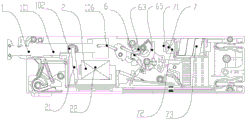
Fig. 1-2 are schematic internal layout views of a first embodiment of the circuit breaker of the present invention in an open state;
fig. 3 is a schematic diagram of an internal layout of a first embodiment of the circuit breaker according to the present invention in a closed state;
fig. 4 is a schematic view of another embodiment of the circuit breaker button mechanism of the present invention;
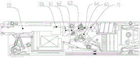
fig. 5-6 are schematic diagrams of the internal layout of another embodiment of the circuit breaker of the present invention;
FIG. 7 is a schematic view of the embodiment of FIG. 5 showing a part A in an open state;
FIG. 8 is a schematic diagram of the closing state of part A in the embodiment of FIG. 5;
FIG. 9 is a movement track diagram of the driving end of the linkage lever when the brake is switched on and off in the embodiment of FIG. 5;
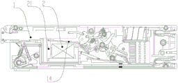
fig. 10-11 are schematic internal layout views of yet another embodiment of the circuit breaker of the present invention.
Detailed Description
The following describes the circuit breaker according to the present invention with reference to the accompanying drawings. The circuit breaker of the present invention is not limited to the description of the following embodiments.
The utility model provides a circuit breaker, includes circuit breaker casing 3, button mechanism 1 and lever mechanism 6, manual operation button mechanism 1, button mechanism 1 drive circuit breaker divide-shut brake through lever mechanism 6, and electromagnetic actuating mechanism 2 is used for driving the circuit breaker to close a floodgate with button mechanism 1 or the cooperation of lever mechanism 6, electromagnetic actuating mechanism 2 triggers and drives button mechanism 1 when receiving the command of closing a floodgate, makes button mechanism 1 slide and closes a floodgate through lever mechanism 6 drive circuit breaker, realizes the automatic combined floodgate of remote control circuit breaker.
The circuit breaker adopts the electromagnetic actuating mechanism 2 to drive the button mechanism 1 or the lever mechanism 6 to close, has high reliability and long service life, effectively solves the problems of gear abrasion or damage or matching dislocation between gears of the existing closing device of the motor and the gear and has short service life, and the electromagnetic actuating mechanism 2 acts quickly and can drive the circuit breaker to close quickly. In particular, it is preferred that the electromagnetic actuator 2 drives the button mechanism 1 to close, and the electromagnetic actuator 2 is adapted to cooperate with the linearly moving button mechanism 1.
As a technical solution of the present invention, preferably, the circuit breaker further includes a release 7, and the release 7 acts to trigger the lever mechanism 6 to release, so as to open the circuit breaker, thereby implementing remote control of automatic opening of the circuit breaker. The automatic opening and closing of the remote control circuit breaker are realized through the matching of the electromagnetic actuating mechanism 2 and the button mechanism 1 and the matching of the release 7 and the lever mechanism 6.
As another technical solution of the present invention, it is preferable that the electromagnetic actuating mechanism 2 cooperates with the button mechanism 1 to drive the circuit breaker to open and close. When the breaker is in an opening state, the electromagnetic actuating mechanism 2 triggers and drives the button mechanism 1 when receiving a closing command, so that the button mechanism 1 slides and drives the breaker to close through the lever mechanism 6; meanwhile, in a closing state of the circuit breaker, the electromagnetic actuating mechanism 2 triggers and drives the button mechanism 1 when receiving a switching-off command, so that the button mechanism 1 slides and drives the circuit breaker to switch off through the lever mechanism 6. The circuit breaker of this scheme adopts same electromagnetic actuating mechanism 2 drive button mechanism 1 to divide-shut brake, not only makes compact structure cost reduction, and the reliability is high and long service life moreover, and electromagnetic actuating mechanism 2 acts rapidly simultaneously, can drive the quick divide-shut brake of circuit breaker. As shown in fig. 1-3, a circuit breaker according to a first embodiment of the circuit breaker of the present invention includes a circuit breaker housing 3, a button mechanism 1, an electromagnetic actuating mechanism 2, a lever mechanism 6, a moving contact 10, a stationary contact 11, an arc extinguishing device 9, and a release 7; the button mechanism 1 is connected with the lever mechanism 6, the lever mechanism 6 is connected with the moving contact 10, the static contact 11 is arranged in the breaker shell 3 and corresponds to the moving contact 10, the button mechanism 1 is pressed and pulled, and the button mechanism 1 drives the breaker to be switched on and switched off respectively through the lever mechanism 6. The electromagnetic actuating mechanism 2 triggers and drives the button mechanism 1 when receiving a closing command, so that the button mechanism 1 slides and drives the circuit breaker to close through the lever mechanism 6, and the automatic closing of the remote control circuit breaker is realized; and the release 7 acts to trigger the lever mechanism 6 to release when receiving a switching-off command, so that the circuit breaker is switched off, and the automatic switching-off of the circuit breaker is remotely controlled.
Preferably, the electromagnetic actuating mechanism 2 and the release 7 can receive a switching-on signal and a switching-off signal of an upper computer, such as an intelligent terminal, an electric energy meter, a switch cabinet and the like, through a signal terminal 5 arranged on the circuit breaker housing 3. Alternatively, the electromagnetic actuating mechanism 2 and the trip unit 7 can also receive a closing signal and an opening signal of a microcontroller inside the circuit breaker.
Preferably, the circuit breaker further comprises an overload release 8, the lever mechanism 6 comprises a snap-fit jump buckle 64 and a lock catch 65, the overload release 8 comprises a bimetallic strip, and the bimetallic strip is bent and driven when in overload to drive the lock catch 65 on the lever mechanism 6, so that the lever mechanism 6 is released to realize circuit breaker opening. When the circuit breaker fails, the release 7 automatically triggers the lock catch 65 of the lever mechanism 6, and the release enables the lever mechanism 6 to release to realize circuit breaker opening; the release 7 may be an electromagnetic short-circuit release and/or an overload release and/or an electric leakage release, and the like, and automatically operates to drive the latch 65 of the lever mechanism 6 when the breaker is short-circuited, overloaded or leaked. For example, the release 7 is an oil damping release, and may have both short-circuit protection and overload protection functions, and the release 7 may control the release 7 to operate to implement opening protection when the microcontroller detects undervoltage or overvoltage. As shown in fig. 2, the trip unit 7 includes a shunt trip unit 72 at the front end and a short-circuit protection trip unit 73 at the rear end, wherein the shunt trip unit 72 can be tripped by the control signal triggering lever mechanism 6, the short-circuit protection mechanism 73 can trigger the lever mechanism 6 to trip when a short-circuit fault occurs in the line, and the shunt trip unit 72 and the short-circuit protection trip unit 73 are of an integrated structure.
As shown in fig. 2, the electromagnetic actuating mechanism 2 includes an electromagnetic main body provided with a coil 22 and a linkage rod 21, and the electromagnetic main body drives the button mechanism 1 through the linkage rod 21 to open the circuit breaker. As shown in fig. 2, in an embodiment in which the electromagnetic actuating mechanism 2 is matched with the button mechanism 1, the electromagnetic actuating mechanism 2 includes an electromagnetic main body provided with a coil 22 and an iron linkage rod 21, the linkage rod 21 is made of a material capable of being magnetically attracted, the button mechanism 1 includes a button 101 provided with a button groove 102, the button 101 is drivingly connected with the lever mechanism 6 through a first connecting rod 106, one end of the linkage rod 21 is connected to the electromagnetic actuating mechanism 2 or the housing 3 and can swing around the end (a direct-acting type can also be provided), and the other end of the linkage rod 21 is installed in the button groove 102 of the button 101.
As shown in fig. 2, the circuit breaker is in a switching-off state, when the circuit breaker is automatically switched on, when a coil 22 of the electromagnetic actuating mechanism 2 is powered on, the linkage rod 21 is attracted by the action of a coil magnetic field to drive the button 101 to move towards the inside of the circuit breaker, when the button 101 moves, the rotating part 61 is driven to rotate clockwise by the first connecting rod 106 to drive the connecting rod mechanism 6 to make the moving contact 10 contact with the static contact 11 for switching on, so that automatic switching-on is realized, when the coil of the electromagnetic actuating mechanism 2 is powered off, the linkage rod 21 is reset by the linkage rod reset spring, and certainly, a multiple linkage rod. The circuit breaker is now in the closed state shown in fig. 3.
As shown in fig. 3, when the circuit breaker is in a closed state and automatic opening is performed, the release 7 is powered on, the ejector rod 71 in the release 7 acts to push the latch 65 of the lever mechanism 6 to rotate counterclockwise, the hasp connection between the latch 65 and the trip catch 63 is released, the lever mechanism 6 is tripped to realize opening of the circuit breaker, and the button spring drives the button 101 to reset.
As shown in fig. 2, the circuit breaker is in an open state, when the circuit breaker is manually closed, the manual pressing button 101 moves towards the inside of the circuit breaker, when the button 101 moves, the first connecting rod 106 drives the rotating member 61 to rotate clockwise, the connecting rod mechanism 6 is driven to make the moving contact 10 contact with the static contact 11 for closing, so as to implement manual closing, and meanwhile, the button 101 also drives the linkage rod 21 to rotate to a position close to the electromagnetic main body, so that the circuit breaker is in a closed state shown in fig. 3.
As shown in fig. 3, the circuit breaker is in a closing state, when the circuit breaker is manually opened, the button 101 is manually pulled to move towards the outside of the circuit breaker, when the button 101 moves, the rotating member 61 is driven to rotate counterclockwise by the first connecting rod 106, the connecting rod mechanism 6 is driven to separate the moving contact 10 from the static contact 11, so that manual opening is realized, meanwhile, the button 101 also drives the linkage rod 21 to rotate to a position relatively far away from the electromagnetic main body, and at this time, the circuit breaker is in the closing state shown in fig. 3.
Another improvement point of the electromagnetic actuating mechanism 2 adopting the scheme is that how to avoid the influence of the automatic opening and closing device on the manual opening and closing operation does not need to be considered like the automatic opening and closing scheme of the existing motor and gear mechanism. According to the existing automatic switching-on and switching-off scheme of the motor and the gear mechanism, a microswitch or a contact or a sensor needs to be set to monitor the switching-on position, the switching-off position and/or the initial position of the motor or the gear, the gear needs to be stopped or reversed after rotating to the corresponding position, and a corresponding avoiding mechanism needs to be arranged on the gear mechanism or the button mechanism, so that the switching-off or switching-on operation can still be carried out by driving the button mechanism in a manual mode after the motor and the gear mechanism drive the circuit breaker to be switched on or switched off. The electromagnetic actuating mechanism 2 of the scheme does not need to be designed correspondingly, the electromagnetic actuating mechanism 2 only has two states of an attraction linkage rod 21 and a non-attraction linkage rod 21, the button 101 is driven to realize closing when the linkage rod 21 is attracted, then the coil 22 of the electromagnetic actuating mechanism 2 is powered off, the linkage rod 21 is not attracted any more, the button 101 can be pulled manually, the linkage rod 21 is driven by the button 101 to swing and reset, meanwhile, the rotating part 61 is driven by the first connecting rod 106 to rotate anticlockwise to realize manual opening and closing, the button 101 can be pressed again to realize manual closing, the structure is simple, and the mutual influence is avoided.
As another embodiment, the electromagnetic actuating mechanism 2 may also drive the linkage rod 21 in a manner of a top rod, the linkage rod 21 may be a non-magnetic attracted plastic part, the linkage rod 21 is rotatably installed in the circuit breaker housing 3, one end of the linkage rod is arranged corresponding to the top rod of the electromagnetic actuating mechanism 2, the other end of the linkage rod is arranged corresponding to the button mechanism 1, and the electromagnetic actuating mechanism 2 is powered on and impacts one end of the linkage rod 21 through the top rod, so that the other end of the linkage rod 21 drives the button mechanism 1 to move for switching-on operation.
As another embodiment, a sliding groove for the linkage rod 21 to slide linearly is formed in the circuit breaker housing, one end of the linkage rod 21 is arranged corresponding to the electromagnetic actuating mechanism 2, the other end of the linkage rod 21 is matched with the button mechanism 1, and the electromagnetic actuating mechanism 2 is powered to drive the linkage rod 21 to slide, so that the linkage rod 21 drives the button mechanism 1 to move to close the switch. The electromagnetic actuating mechanism 2 is electrified to attract the linkage rod 21 to slide, and the button mechanism 1 is pulled to be switched on through a draw hook on the linkage rod 21; or, the electromagnetic actuating mechanism 2 is electrified to impact the linkage rod 21 to slide, and the linkage rod 21 pushes the button mechanism 1 to be switched on. After the electromagnetic actuating mechanism 2 is powered off, the linkage rod 21 is reset through a linkage rod spring, or is driven by the button mechanism 1 to reset when the brake is switched off again.
As another degradation example, two electromagnetic actuating mechanisms 2 may be provided, one for driving the button mechanism 1 to perform a closing operation and one for driving the button mechanism 1 to perform an opening operation, without triggering the opening through the release 7, so that too many mechanisms are adopted, and the circuit breaker has a large volume and high cost.
As another embodiment, as shown in fig. 4, the button mechanism 1 includes a button 101, a button link 103, a button transmission rod 104, and a first link 106, which are connected in sequence, a button protrusion 105 engaged with the linkage rod 21 is disposed on the button 101, the button link 103, or the button transmission rod 104, in this embodiment, the button protrusion 105 is disposed on the button transmission rod 104, one end of the button 101 protrudes out of the circuit breaker housing 3 for operation, the button transmission rod 104 is linearly and slidably mounted in the circuit breaker housing 3, the button 101, the button link 103, the button transmission rod 104, and the first link 106 sequentially drive the lever mechanism 6, and the circuit breaker performs a switching operation, the button 101, the button link 103, and the button transmission rod 104 replace the relatively long button 101, and the button 101, the button link 103, or the button transmission rod 104 is conveniently engaged with a plug-in locking mechanism. The linkage rod 21 is rotatably arranged in the breaker shell 3, one end of the linkage rod corresponds to the electromagnetic actuating mechanism 2, the other end of the linkage rod corresponds to the button protrusion 105, the electromagnetic actuating mechanism 2 triggers the linkage rod 21 to rotate when powered on, the linkage rod 21 drives the button transmission rod 104 to slide through the button protrusion 105 to drive the rotating part 61 to rotate anticlockwise through the first connecting rod 106 so as to realize switching-on, and meanwhile, the button 101 is also driven to slide to the switching-on position shown in fig. 3 so as to realize automatic switching-on.
It should be noted that the button mechanism 1 may also be opened when pressed and closed when pulled, the electromagnetic actuating mechanism 2 may also be arranged in a rotating manner, and the attracting end of the electromagnetic main body of the electromagnetic actuating mechanism 2 is arranged toward one side of the lever mechanism. The linkage rod 21 can be installed in a rotating mode or a direct-acting mode, and corresponding limiting convex ribs or limiting grooves can be further arranged in the breaker shell 3 and used for guiding and limiting the rotating range or the sliding range of the linkage rod 21. The button mechanism 1 may be provided with a button slot 102, and may also be provided with other matching structures such as a button protrusion matched with the linkage rod 21, which all belong to the protection scope of the present invention.
As shown in fig. 3, the button mechanism 1 includes a button 101 having a button slot 102, the button 101 is drivingly connected to the lever mechanism 6 via a first link 106, and a button spring is drivingly connected to the button 101 to move out of the circuit breaker housing 3. The lever mechanism of the present invention is a four/five-bar structure, as shown in fig. 3, in an embodiment of the lever mechanism 6 of the present invention, the lever mechanism 6 includes a rotating member 61, a second connecting bar 62, a trip catch 63, a latch 65, and a main lever 64, the rotating member 61 and the main lever 64 are rotatably installed in the circuit breaker housing 3, the trip catch 63 and the latch 65 are respectively rotatably installed on the main lever 64 and are in a latch connection, the rotating member 61 is in a driving connection with the trip catch 63 through the second connecting bar 62, and is connected with the button mechanism 1 through the first connecting bar 106, the main lever 64 is connected with the movable contact 10, and a latch spring is connected with the latch 65 to provide a reset force for the latch 65 to rotate in a direction of being in the latch connection with the trip catch. Of course, other four/five bar linkage arrangements may be used for the lever mechanism 6.
Preferably, as shown in fig. 1, the circuit breaker of this embodiment is a plug-in circuit breaker, the button mechanism 1 and the first connection terminal 12 are disposed at one end of the circuit breaker, the second connection terminal 4 and the signal terminal 5 are disposed at the other end of the circuit breaker, the lever mechanism 6 is disposed in the middle of the circuit breaker, the electromagnetic actuating mechanism 2 and the first connection terminal 12 are disposed at the same side of the button mechanism 1, the electromagnetic actuating mechanism 2 is disposed between the lever mechanism 6 and the first connection terminal 12, the arc extinguishing device 9 and the trip 7 are disposed side by side and between the lever mechanism 6 and the second connection terminal 4, the overload trip 8 and the lever mechanism 6 are disposed side by side and between the electromagnetic actuating mechanism 2 and the arc extinguishing device 9, the circuit breaker of this embodiment has a reasonable internal layout design, a compact layout among the components, and can effectively reduce the overall specification of the circuit breaker, the miniaturization development trend of the circuit breaker is met.
As another technical solution of the present invention, the electromagnetic actuating mechanism 2 cooperates with the lever mechanism 6 to drive the circuit breaker to close. For example, the electromagnetic actuator 2 drives the rotor 61 to rotate in the closing direction to close the door. In one embodiment, a closing driving arm protrudes from the rotating member 61, and the electromagnetic actuating mechanism 2 triggers to push or pull the closing driving arm to rotate the rotating member 61 in a closing direction to achieve closing when receiving a closing command. As another embodiment, the electromagnetic actuating mechanism 2 drives the rotating part 61 through the linkage rod 21 to close the circuit breaker, the linkage rod 21 is rotatably installed on the electromagnetic actuating mechanism 2 or the housing 3, the electromagnetic actuating mechanism 2 pushes or attracts the linkage rod 21 when receiving a closing command, and the linkage rod 21 drives the rotating part 61 to rotate towards the opening direction to realize opening.
As shown in fig. 5 to 6, another embodiment of the circuit breaker of the present invention, which has the same general structure and function as the first embodiment, includes a circuit breaker housing 3, a button mechanism 1, an electromagnetic actuating mechanism 2, a lever mechanism 6, a movable contact 10, a fixed contact 11, an arc extinguishing device 9, a trip 7, a first connection terminal 12, a second connection terminal 4, and a signal terminal 5. The present embodiment differs from the first embodiment in that the same electromagnetic actuating mechanism 2 is used in conjunction with the button mechanism 1 for driving the circuit breaker to close and open.
When the circuit breaker is in a switching-off state, the button mechanism 1 is manually pressed, the button mechanism 1 drives the circuit breaker to be switched on through the lever mechanism 6, or when a coil 22 of the electromagnetic actuating mechanism 2 is powered on, the linkage rod 21 is attracted under the action of a coil magnetic field, the button mechanism 1 is driven to move towards the interior of the circuit breaker to drive the circuit breaker to be switched on, and then the electromagnetic actuating mechanism 2 is powered off.
When the circuit breaker is in a closing state, the button mechanism 1 is pressed again to drive the circuit breaker to open the brake through the lever mechanism 6, so that manual brake opening is realized; or, when the coil 22 of the electromagnetic actuating mechanism 2 is powered on, the linkage rod 21 is attracted under the action of the magnetic field of the coil, the button 101 is driven to move towards the inside of the circuit breaker, the circuit breaker is driven to be opened, automatic opening is realized, and then the electromagnetic actuating mechanism 2 is powered off.
As shown in fig. 5-6, the lever mechanism 6 includes a link lever 14 connected to the button mechanism 1, a guide groove 31 is arranged in the breaker shell 3, one end of the linkage lever 14 is rotatably arranged on the button mechanism 1, the other end is a driving end 141 and is arranged in the guide groove 31, when the breaker is in a breaking state, the button mechanism 1 is pressed to drive the button mechanism 1 to move towards the interior of the shell 3 of the circuit breaker, the button mechanism 1 drives the circuit breaker to close, at the same time, the driving end 141 of the linkage lever 14 moves to the position matched with the lock catch 65 of the lever mechanism 6 under the guiding of the guide slot 31, when the breaker is in a closing state, when the button mechanism 1 is pressed again, the driving end 141 of the linkage lever 14 drives the lock catch 65 to rotate, so that the lock catch 65 and the trip catch 63 are unlocked and matched, the lever mechanism 6 is tripped to realize the opening of the circuit breaker, and the driving end 141 of the linkage lever 14 returns to the initial position.
As shown in fig. 7-9, a guide groove 31 and a guide boss 311 located in the guide groove 31 are disposed on an inner side wall of the circuit breaker housing 3, the guide groove 31 surrounds the guide boss 311, when the button mechanism 1 is pressed, the button mechanism 1 drives the driving end 141 of the link lever 14 to slide from one side of the guide boss 311 to a position matched with the latch 65, and when the button mechanism 1 is pressed again, the link lever 14 is driven to trigger the lever mechanism 6 to trip, so as to achieve circuit breaker opening, the button spring drives the button 101 to reset, and simultaneously drives the driving end 141 of the link lever 14 to reset from the other side of the guide boss 311, and the driving end 141 of the link lever 14 moves around the guide boss 311 in the guide groove 31.
In a specific preferred embodiment, as shown in fig. 7-9, the guide slot 31 includes a first guide slot 310, a second guide slot 312, a third guide slot 313, a fourth guide slot 314 and a fifth guide slot 315 which are sequentially communicated, the first guide slot 310, the second guide slot 312, the third guide slot 313, the fourth guide slot 314 and the fifth guide slot 315 are connected to form a ring-shaped guide slot 31 surrounding the guide boss 311, the first guide slot 310 extends outward to form a Y shape with the second guide slot 312 and the fifth guide slot 315, the third guide slot 313 and the fourth guide slot 314 are communicated and are opposite to the guide side surface 316 on one side of the guide boss 311, when the button mechanism 1 drives the breaker to close, the driving end 141 of the linkage lever 14 enters the third guide slot 313 from the first guide slot 310 and the second guide slot 312, after the breaker closes, the button mechanism 1 is slightly reset (a multi-pressed portion or a reset contact of an over-travel portion is driven by the button spring), the button mechanism 1 drives the driving end 141 of the linkage lever 14 to enter the fourth guide groove 314 under the guidance of the guide side surface 316 and is arranged opposite to the lock catch 65; when the button mechanism 1 is pressed again, the button mechanism 1 drives the driving end 141 of the linkage lever 14 to move towards the side away from the fifth guide groove 315 to trigger the lever mechanism 6 to release, so as to realize the brake separation, and then the button mechanism 1 is reset under the driving of the button spring to drive the driving end 141 of the linkage lever 14 to return to the initial position of the first guide groove 310 from the fourth guide groove 314 and the fifth guide groove 315.
Preferably, the second guide groove 312 is an inclined slope, the highest edge surface of the slope of the second guide groove 312 is engaged with the guide side surface 316 of the boss 311 and is communicated with the third guide groove 313, and the groove surface of the third guide groove 313 is lower than the second guide groove 312, so that the driving end 141 of the linking lever 14 cannot return to the second guide groove 312 after entering the third guide groove 313 from the first guide groove 310 and the second guide groove 312, but enters the fourth guide groove 314 along the guide side surface 316. Further, the groove surface of the fourth guide groove 314 is lower than the groove surface of the third guide groove 313, the fifth guide groove 315 is a guide slope, the highest edge surface of the guide slope of the fifth guide groove 315 is connected to the first guide groove 310, and the connection surface of the fifth guide groove 315 and the first guide groove 310 is higher than the first guide groove 310, so that the circuit breaker cannot return to the third guide groove 313 from the fourth guide groove 314 but returns to the first guide groove 310 along the fifth guide groove 315 when the circuit breaker is opened.
Of course, the linkage lever 14 is moved to a position matched with the latch 65 of the lever mechanism 6 when the circuit breaker is switched on, so that the linkage lever 14 can be restored to the initial position by the structure that the linkage lever 14 drives the lever mechanism 6 to be tripped when the button mechanism 1 is pressed again, and other similar existing technical solutions can also be adopted.
In this embodiment, the structure of the lever mechanism 6 is the same as that of the first embodiment, and is not described again. The lock catch 65 is rotatably mounted and provided with a lock catch arm in snap-fit with the jump catch 63, a first driving arm and a second driving arm which are respectively matched with the release 7 and the overload release 8, and a third driving arm which is matched with the linkage lever 14, and the linkage lever 14 can share one driving arm with the release 7 and the overload release 8. Of course, other protective releases may be used without the release 7 or the overload release 8, if desired.
In the circuit breaker of the embodiment, the circuit breaker is in an open state, when the circuit breaker is automatically switched on, the electromagnetic actuating mechanism 2 is powered on, the linkage rod 21 is attracted by electromagnetic force, the button mechanism 1 is driven to move to the switch-on state towards the right side, the button mechanism 1 drives the driving end 141 of the linkage lever 14 to enter the third guide groove 313, meanwhile, the button mechanism 1 drives the rotating part 61 to rotate clockwise through the first connecting rod 106, the connecting rod mechanism 6 is driven to enable the moving contact 10 to be in contact with the fixed contact 11 for switch-on, automatic switch-on is achieved, after the electromagnetic actuating mechanism 2 is powered off, the linkage rod 21 returns to the initial position under the spring counterforce, the button mechanism 1 is driven by the button spring to reset to the left by a small stroke and drives the driving end 141 of the linkage lever 14 to enter the fourth guide groove 314.
Under the current closing state, when automatic separating brake, electromagnetic actuating mechanism 2 is electrified again, gangbar 21 attracts to coil 22 side, drive button mechanism 1 to the motion of right side, ganged lever 14 slides in fourth guide way 314 region according to the arrow direction, drive end 141 supports and pushes away hasp 65 this moment, make jump buckle 63 and hasp 65 remove the hasp cooperation, lever mechanism 6 collapses and realizes the circuit breaker separating brake, after the coil outage, under the effect of button spring, button mechanism 1 resets left and drives ganged lever 14 and slides to reset in first guide way 310 through fifth guide way 315 according to the arrow direction.
As another technical scheme of the invention, the electromagnetic actuating mechanism 2 and the lever mechanism 6 are matched to drive the circuit breaker to open and close. For example, when receiving a closing command, the electromagnetic actuating mechanism 2 drives the rotating member 61 to rotate to achieve closing, and at the same time, the rotating member 61 also drives the button mechanism 1 to move into the circuit breaker housing 3, so that the linkage lever 14 moves to a position where it is engaged with the latch 65 of the lever mechanism 6. When receiving a closing command, the electromagnetic actuating mechanism 2 pushes the lever mechanism 6 to rotate in the same direction as that of closing again, so as to drive the button mechanism 1 to move in the breaker shell 3, and the linkage lever 14 drives the lock catch 65 to realize tripping and opening. The electromagnetic actuating mechanism 2 can be directly matched with a closing driving arm of the rotating part 61 or matched with the rotating part 61 through the linkage rod 21.
It should be noted that, similar to the first embodiment, the electromagnetic actuating mechanism 2 may also drive the linkage rod 21 in a manner of a push rod, and the button mechanism 1 may adopt other schemes similar to fig. 4, which all belong to the protection scope of the present invention.
As shown in fig. 9-10, the third embodiment of the present invention is substantially the same in structure as the embodiment of fig. 5-9, except that the interlocking lever 14 is connected at one end to the electromagnetic actuator 2, not to the button mechanism 1. A guide groove 31 is formed in the breaker shell 3, one end of the linkage lever 14 is rotatably installed on the linkage rod 21, and the other end of the linkage lever is a driving end 141 and is arranged in the guide groove 31.
The electromagnetic actuating mechanism 2 drives the button mechanism 1 through a linkage rod 21, one end of the linkage rod 21 is arranged corresponding to the electromagnetic actuating mechanism 2, and the other end of the linkage rod is linked with the button mechanism 1. As shown in fig. 9, a button slot is provided on the button mechanism 1, one end of the linkage rod 21 is rotatably installed on the circuit breaker housing 3 or the electromagnetic actuating mechanism 2, and the other end of the linkage rod extends into the button slot to be linked with the button mechanism 1, the electromagnetic actuating mechanism 2 attracts or impacts the linkage rod 21 to drive the button mechanism 1 by the button mechanism 1, and when the button mechanism 1 is pressed, the button mechanism 1 also drives the linkage rod 21 to act. When the circuit breaker is in a switching-off state, the electromagnetic actuating mechanism 2 drives the linkage rod 21 to act, the linkage rod 21 drives the button mechanism 1 to move towards the inside of the circuit breaker to enable the circuit breaker to be switched on, and automatic switching-on is achieved, or the button mechanism 1 is pressed to move towards the inside of the circuit breaker to enable the circuit breaker to be switched on manually, and meanwhile the button mechanism 1 drives the linkage rod 21. Namely, the electromagnetic actuating mechanism 2 drives the linkage rod 21, or the button mechanism 1 drives the linkage rod 21, the linkage rod 21 drives the linkage lever 14 to enable the driving end 141 to move to a position matched with the lock catch 65 of the lever mechanism 6 under the guiding of the guide groove 31; when the circuit breaker is in a closing state, the electromagnetic actuating mechanism 2 drives the linkage rod 21 to drive the button mechanism 1 to move towards the interior of the circuit breaker, or the button mechanism 1 is pressed to move towards the interior of the circuit breaker to drive the linkage rod 21, the linkage rod 21 drives the linkage lever 14, the driving end 141 drives the lock catch 65 to enable the lever mechanism 6 to be tripped to achieve circuit breaker opening, and the driving end 141 of the linkage lever 14 returns to an initial position.
The foregoing is a more detailed description of the invention in connection with specific preferred embodiments and it is not intended that the invention be limited to these specific details. For those skilled in the art to which the invention pertains, several simple deductions or substitutions can be made without departing from the spirit of the invention, and all shall be considered as belonging to the protection scope of the invention.
Claims (11)
1. The utility model provides a circuit breaker, includes button mechanism (1) and lever mechanism (6), button mechanism (1) is connected with lever mechanism (6), button mechanism (1) drives circuit breaker divide-shut brake, its characterized in that through lever mechanism (6): the circuit breaker further comprises an electromagnetic actuating mechanism (2) which is matched with the button mechanism (1) or the lever mechanism (6) and used for driving the circuit breaker to be switched on and switched off.
2. The circuit breaker of claim 1, wherein: when the circuit breaker is in a switching-off state, the electromagnetic actuating mechanism (2) drives the button mechanism (1) to move towards the interior of the circuit breaker through the linkage rod (21) to realize switching-on; and when the circuit breaker is in a closing state, the electromagnetic actuating mechanism (2) drives the button mechanism (1) to move towards the interior of the circuit breaker through the linkage rod (21) to realize opening.
3. The circuit breaker of claim 2, wherein: the linkage rod (21) is made of a material capable of being attracted magnetically, the button mechanism (1) comprises a button (101) provided with a button groove (102), one end of the linkage rod (21) is connected to the electromagnetic actuating mechanism (2) or the shell (3), and the other end of the linkage rod (21) is installed in the button groove (102) of the button (101).
4. The circuit breaker of claim 2, wherein: the linkage rod (21) is rotatably installed in the breaker shell (3), one end of the linkage rod corresponds to the electromagnetic actuating mechanism (2), the other end of the linkage rod corresponds to the button mechanism (1), and when the electromagnetic actuating mechanism (2) is electrified, the linkage rod (21) is attracted or pushed to drive the button mechanism (1) to move so as to carry out switching-on operation.
5. The circuit breaker of claim 2, wherein: when the circuit breaker is in an opening state, the button mechanism (1) is pressed, the button mechanism (1) drives the circuit breaker to be closed through the lever mechanism (6), when the circuit breaker is in a closing state, the button mechanism (1) is pressed, and the button mechanism (1) drives the circuit breaker to be opened through the lever mechanism (6).
6. The circuit breaker of claim 1, wherein: the circuit breaker comprises a linkage lever (14) connected with a button mechanism (1), a guide groove (31) is arranged in a circuit breaker shell (3), one end of the linkage lever (14) is rotatably arranged on the button mechanism (1), the other end is a driving end (141) and is arranged on the guide groove (31), when the breaker is in a switching-off state, the button mechanism (1) moves towards the interior of the breaker to drive the breaker to switch on, meanwhile, the driving end (141) of the linkage lever (14) moves to the position matched with the lock catch (65) of the lever mechanism (6) under the guide of the guide groove (31), when the breaker is in a closing state, the button mechanism (1) moves towards the interior of the circuit breaker, the driving end (141) of the linkage lever (14) drives the lock catch (65) to enable the lever mechanism (6) to be tripped to achieve circuit breaker opening, and the driving end (141) of the linkage lever (14) returns to the initial position.
7. The circuit breaker of claim 2, wherein: the circuit breaker comprises a linkage lever (14) connected with an electromagnetic actuating mechanism (2), a guide groove (31) is formed in a circuit breaker shell (3), one end of the linkage lever (14) is rotatably installed on a linkage rod (21), the other end of the linkage lever is a driving end (141) and is arranged in the guide groove (31), one end of the linkage rod (21) is arranged corresponding to the electromagnetic actuating mechanism (2), and the other end of the linkage rod is linked with a button mechanism (1); when the breaker is in a switching-off state, the electromagnetic actuating mechanism (2) drives the linkage rod (21) to drive the button mechanism (1) to move towards the inside of the breaker to switch on the breaker, or the button mechanism (1) is pressed to move towards the inside of the breaker to switch on the breaker and drive the linkage rod (21), the linkage rod (21) drives the linkage lever (14) to enable the driving end (141) to move to a position matched with a lock catch (65) of the lever mechanism (6) under the guiding of the guide groove (31), when the breaker is in a switching-on state, the electromagnetic actuating mechanism (2) drives the linkage rod (21) to drive the button mechanism (1) to move towards the inside of the breaker, or the button mechanism (1) is pressed to move towards the inside of the breaker to drive the linkage rod (21), the linkage rod (21) drives the linkage lever (14), and the driving end (141) drives the lock catch (65) to enable the lever mechanism, the driving end (141) of the linkage lever (14) returns to the initial position.
8. The circuit breaker according to claim 6 or 7, characterized in that: the guide groove (31) comprises a first guide groove (310), a second guide groove (312), a third guide groove (313), a fourth guide groove (314) and a fifth guide groove (315) which are sequentially communicated, the first guide groove (310), the second guide groove (312), the third guide groove (313), the fourth guide groove (314) and the fifth guide groove (315) are connected to form an annular guide groove (31) surrounding the guide boss (311), the first guide groove (310) extends outwards to form a Y shape with the second guide groove (312) and the fifth guide groove (315), the third guide groove (313) and the fourth guide groove (314) are communicated and are opposite to a guide side surface (316) on one side of the guide boss (311), when the button closing mechanism (1) drives the breaker, a driving end (141) of the linkage lever (14) is driven to enter the third guide groove (313) from the first guide groove (310) and the second guide groove (312), after the breaker is switched on, the button mechanism (1) is driven by the button spring to slightly reset to drive the driving end (141) of the linkage lever (14) to enter the fourth guide groove (314) under the guidance of the guide side surface (316), and the button mechanism is arranged opposite to the lock catch (65); and pressing the button mechanism (1) again, wherein the button mechanism (1) drives the driving end (141) of the linkage lever (14) to move towards one side far away from the fifth guide groove (315) to trigger the lever mechanism (6) to trip to realize brake separation, and the button mechanism (1) is reset under the driving of the button spring to drive the driving end (141) of the linkage lever (14) to return to the initial position of the first guide groove (310) from the fourth guide groove (314) and the fifth guide groove (315).
9. The circuit breaker of claim 1, wherein: lever mechanism (6) are including rotating piece (61), second connecting rod (62), jump knot (63), hasp (65), main lever (64), rotate piece (61) and main lever (64) and rotate and install in circuit breaker casing (3), jump knot (63) and hasp (65) rotate respectively and install on main lever (64) and hasp connection, rotate piece (61) and jump knot (63) drive through second connecting rod (62) and be connected, be connected with button mechanism (1) through first connecting rod (106), main lever (64) are connected with moving contact (10), and the hasp spring is connected with hasp (65) and provides hasp (65) to the reset force that connects the direction pivoted with jump knot (63) hasp.
10. The circuit breaker of claim 2, wherein: the button mechanism (1) comprises a button (101), a button connecting rod (103), a button transmission rod (104) and a first connecting rod (106) which are sequentially connected, and the linkage rod (21) drives the circuit breaker to be switched on through the button (101) or the button connecting rod (103) or the button transmission rod (104).
11. The circuit breaker of claim 2, wherein: the linkage rod (21) is slidably mounted in the breaker shell (3), one end of the linkage rod (21) is arranged corresponding to the electromagnetic actuating mechanism (2), the other end of the linkage rod is matched with the button mechanism (1), and the electromagnetic actuating mechanism (2) is electrified to drive the linkage rod (21) to slide, so that the linkage rod (21) drives the button mechanism (1) to move to perform switching-on.
Priority Applications (1)
| Application Number | Priority Date | Filing Date | Title |
|---|---|---|---|
| CN202010628286.3A CN111681928A (en) | 2020-07-02 | 2020-07-02 | Circuit breaker |
Applications Claiming Priority (1)
| Application Number | Priority Date | Filing Date | Title |
|---|---|---|---|
| CN202010628286.3A CN111681928A (en) | 2020-07-02 | 2020-07-02 | Circuit breaker |
Publications (1)
| Publication Number | Publication Date |
|---|---|
| CN111681928A true CN111681928A (en) | 2020-09-18 |
Family
ID=72457088
Family Applications (1)
| Application Number | Title | Priority Date | Filing Date |
|---|---|---|---|
| CN202010628286.3A Pending CN111681928A (en) | 2020-07-02 | 2020-07-02 | Circuit breaker |
Country Status (1)
| Country | Link |
|---|---|
| CN (1) | CN111681928A (en) |
Cited By (4)
| Publication number | Priority date | Publication date | Assignee | Title |
|---|---|---|---|---|
| CN112530760A (en) * | 2020-11-27 | 2021-03-19 | 河南平高通用电气有限公司 | Separating brake tripping mechanism and direct current circuit breaker |
| CN114360977A (en) * | 2022-03-10 | 2022-04-15 | 东莞市中汇瑞德电子股份有限公司 | Circuit breaker capable of being remotely controlled |
| CN114883156A (en) * | 2022-07-12 | 2022-08-09 | 东莞市中汇瑞德电子股份有限公司 | Built-in circuit breaker of electromagnetic operating mechanism |
| CN115910712A (en) * | 2022-12-14 | 2023-04-04 | 上海正泰智能科技有限公司 | Circuit breaker |
-
2020
- 2020-07-02 CN CN202010628286.3A patent/CN111681928A/en active Pending
Cited By (7)
| Publication number | Priority date | Publication date | Assignee | Title |
|---|---|---|---|---|
| CN112530760A (en) * | 2020-11-27 | 2021-03-19 | 河南平高通用电气有限公司 | Separating brake tripping mechanism and direct current circuit breaker |
| CN112530760B (en) * | 2020-11-27 | 2023-10-03 | 河南平高通用电气有限公司 | Separating brake tripping mechanism and direct current breaker |
| CN114360977A (en) * | 2022-03-10 | 2022-04-15 | 东莞市中汇瑞德电子股份有限公司 | Circuit breaker capable of being remotely controlled |
| CN114360977B (en) * | 2022-03-10 | 2022-07-05 | 东莞市中汇瑞德电子股份有限公司 | Circuit breaker capable of being remotely controlled |
| CN114883156A (en) * | 2022-07-12 | 2022-08-09 | 东莞市中汇瑞德电子股份有限公司 | Built-in circuit breaker of electromagnetic operating mechanism |
| CN115910712A (en) * | 2022-12-14 | 2023-04-04 | 上海正泰智能科技有限公司 | Circuit breaker |
| CN115910712B (en) * | 2022-12-14 | 2023-12-26 | 上海正泰智能科技有限公司 | Circuit breaker |
Similar Documents
| Publication | Publication Date | Title |
|---|---|---|
| CN111681928A (en) | Circuit breaker | |
| CN111681930A (en) | Circuit breaker | |
| JPH08279330A (en) | Breaker | |
| CN214099549U (en) | Circuit breaker | |
| CN213242462U (en) | Circuit breaker | |
| CN115360065A (en) | Plug-in circuit breaker | |
| CN104078288B (en) | A kind of electromagnetic operating mechanism | |
| US6259339B1 (en) | Remotely controllable circuit breaker with combined visual indication of state and manual override | |
| CN216902655U (en) | Tripping device and isolating switch | |
| CN112713065A (en) | Circuit breaker with prevent mistake combined floodgate function | |
| CN210743865U (en) | Low-voltage vacuum circuit breaker | |
| CN115148550A (en) | Circuit breaker capable of being remotely controlled | |
| CN218039075U (en) | Plug-in circuit breaker | |
| CN213635872U (en) | Circuit breaker with prevent mistake combined floodgate function | |
| CN113539759A (en) | Breaker and 5G power distribution cabinet with same | |
| CN216928452U (en) | Bidirectional magnetic latching actuating mechanism of circuit breaker | |
| CN213635873U (en) | Moulded case circuit breaker with prevent mistake combined floodgate function | |
| CN219350113U (en) | Transmission mounting structure of auxiliary alarm and shunt undervoltage accessory of circuit breaker | |
| CN219936975U (en) | Small-sized breaker accessory | |
| CN217333982U (en) | Magnetic flux release reset structure and circuit breaker | |
| CN213583675U (en) | Electric operating mechanism with anti-misoperation function | |
| CN213242445U (en) | Small-sized circuit breaker | |
| CN218333670U (en) | Mechanical switch device of circuit breaker | |
| CN203950759U (en) | A kind of electromagnetic operating mechanism | |
| CN216054517U (en) | Circuit breaker |
Legal Events
| Date | Code | Title | Description |
|---|---|---|---|
| PB01 | Publication | ||
| PB01 | Publication | ||
| SE01 | Entry into force of request for substantive examination | ||
| SE01 | Entry into force of request for substantive examination |