CN111668586B - Antenna with a shield - Google Patents
Antenna with a shield Download PDFInfo
- Publication number
- CN111668586B CN111668586B CN202010052370.5A CN202010052370A CN111668586B CN 111668586 B CN111668586 B CN 111668586B CN 202010052370 A CN202010052370 A CN 202010052370A CN 111668586 B CN111668586 B CN 111668586B
- Authority
- CN
- China
- Prior art keywords
- terminal
- antenna
- facing
- facing portion
- body portion
- Prior art date
- Legal status (The legal status is an assumption and is not a legal conclusion. Google has not performed a legal analysis and makes no representation as to the accuracy of the status listed.)
- Active
Links
Images


Classifications
-
- H—ELECTRICITY
- H01—ELECTRIC ELEMENTS
- H01Q—ANTENNAS, i.e. RADIO AERIALS
- H01Q7/00—Loop antennas with a substantially uniform current distribution around the loop and having a directional radiation pattern in a plane perpendicular to the plane of the loop
-
- H—ELECTRICITY
- H01—ELECTRIC ELEMENTS
- H01Q—ANTENNAS, i.e. RADIO AERIALS
- H01Q21/00—Antenna arrays or systems
- H01Q21/24—Combinations of antenna units polarised in different directions for transmitting or receiving circularly and elliptically polarised waves or waves linearly polarised in any direction
-
- H—ELECTRICITY
- H01—ELECTRIC ELEMENTS
- H01Q—ANTENNAS, i.e. RADIO AERIALS
- H01Q1/00—Details of, or arrangements associated with, antennas
- H01Q1/12—Supports; Mounting means
- H01Q1/22—Supports; Mounting means by structural association with other equipment or articles
-
- H—ELECTRICITY
- H01—ELECTRIC ELEMENTS
- H01Q—ANTENNAS, i.e. RADIO AERIALS
- H01Q1/00—Details of, or arrangements associated with, antennas
- H01Q1/12—Supports; Mounting means
-
- H—ELECTRICITY
- H01—ELECTRIC ELEMENTS
- H01Q—ANTENNAS, i.e. RADIO AERIALS
- H01Q1/00—Details of, or arrangements associated with, antennas
- H01Q1/36—Structural form of radiating elements, e.g. cone, spiral, umbrella; Particular materials used therewith
-
- H—ELECTRICITY
- H01—ELECTRIC ELEMENTS
- H01Q—ANTENNAS, i.e. RADIO AERIALS
- H01Q1/00—Details of, or arrangements associated with, antennas
- H01Q1/36—Structural form of radiating elements, e.g. cone, spiral, umbrella; Particular materials used therewith
- H01Q1/38—Structural form of radiating elements, e.g. cone, spiral, umbrella; Particular materials used therewith formed by a conductive layer on an insulating support
-
- H—ELECTRICITY
- H01—ELECTRIC ELEMENTS
- H01Q—ANTENNAS, i.e. RADIO AERIALS
- H01Q1/00—Details of, or arrangements associated with, antennas
- H01Q1/50—Structural association of antennas with earthing switches, lead-in devices or lightning protectors
-
- H—ELECTRICITY
- H01—ELECTRIC ELEMENTS
- H01Q—ANTENNAS, i.e. RADIO AERIALS
- H01Q5/00—Arrangements for simultaneous operation of antennas on two or more different wavebands, e.g. dual-band or multi-band arrangements
- H01Q5/30—Arrangements for providing operation on different wavebands
- H01Q5/307—Individual or coupled radiating elements, each element being fed in an unspecified way
- H01Q5/342—Individual or coupled radiating elements, each element being fed in an unspecified way for different propagation modes
- H01Q5/357—Individual or coupled radiating elements, each element being fed in an unspecified way for different propagation modes using a single feed point
- H01Q5/364—Creating multiple current paths
Abstract
An antenna mountable on an object. The antenna has a body portion, a facing portion, a first feed terminal, a second feed terminal, and at least one reinforcing terminal. The body portion has a ring shape including a dividing line portion. The dividing line portion extends in a predetermined direction. The dividing line portion has an opening, a first end portion and a second end portion. The first end portion and the second end portion are positioned away from each other in a predetermined direction, leaving an opening therebetween. The facing portion includes a first facing portion and a second facing portion. At least one reinforcement terminal is positioned away from the parting line portion. At least one reinforcement terminal extends from the facing portion. When the antenna is mounted on an object, at least one reinforcement terminal is fixed to the object. The antenna of the present invention has stable antenna performance.
Description
Technical Field
The present invention relates to an antenna mountable on an object.
Background
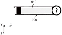
JPA2016-225956 (patent document 1) discloses an antenna 900 of this type.
As understood from fig. 15 and 16, the antenna 900 of patent document 1 is printed on a printed circuit board (object) 910.
The antenna 900 of patent document 1 may have variations in antenna characteristics due to manufacturing variations of the printed circuit board 910.
Disclosure of Invention
Therefore, an object of the present invention is to provide an antenna which can be mounted on an object and has stable antenna characteristics.
If the antenna is formed on a separate member that is different from and separate from the object, the antenna is composed of a main body portion provided with a feeding terminal and a facing portion that is accommodated by the main body portion while constituting a capacitor of the antenna.
In order to make the antenna formed on the discrete member have a certain amount of capacitance, it is necessary that the facing portion protrudes from the main body portion. If a user applies an external force to the facing portion in a state where the antenna is mounted on an object, the facing portion may be deformed, thereby changing the capacitance of the antenna.
The present inventors have found that, if an antenna formed as a separate member is provided with a reinforcing terminal at a facing portion, the facing portion is prevented from being deformed when an external force is applied to the facing portion in a state where the antenna is mounted on an object. The present invention is based on the above finding.
One aspect of the present invention provides an antenna mountable on an object. The antenna has a body portion, a facing portion, a first feed terminal, a second feed terminal, and at least one reinforcing terminal. The body portion has a ring shape including a dividing line portion. The dividing line portion extends in a predetermined direction. The dividing line portion has an opening, a first end portion and a second end portion. The first end portion and the second end portion face away from each other in a predetermined direction, while leaving the opening. The facing portion includes a first facing portion and a second facing portion. The first facing portion is disposed on the first end portion. The second facing portion is disposed on the second end portion. The first facing portion and the second facing portion are spaced apart from and face each other. Each of the first and second feeding terminals is provided on the main body portion. Each of the first and second feeding terminals is fixed to an object when the antenna is mounted on the object. The at least one reinforcing terminal is provided at a position away from the dividing line portion. The at least one reinforcement terminal extends from the facing portion. The at least one reinforcement terminal is secured to the object when the antenna is mounted on the object.
The antenna of the present invention is configured as follows: the antenna has the at least one reinforcing terminal; the at least one reinforcement terminal extends from the facing portion; the at least one reinforcement terminal is fixed to the object when the antenna is mounted on the object; and the at least one reinforcing terminal is provided at a position away from the dividing line portion. This configuration prevents deformation of the facing portion even if an external force is applied to the facing portion in a state where the antenna is mounted on an object. Therefore, the antenna of the present invention has little change in antenna characteristics.
The objectives of the invention, and the structure thereof, will be understood more fully by a study of the following description of the preferred embodiments and by reference to the accompanying drawings.
Drawings
Fig. 1 is a perspective view showing an antenna according to a first embodiment of the present invention.
Fig. 2 is a plan view illustrating the antenna of fig. 1.
Fig. 3 is another perspective view illustrating the antenna of fig. 1.
Fig. 4 is a bottom view illustrating the antenna of fig. 1.
Fig. 5 is a front view illustrating the antenna of fig. 1. In the figure, the objects are shown with dashed lines.
Fig. 6 is a side view illustrating the antenna of fig. 1. In the figure, the objects are shown with dashed lines.
Fig. 7 is a rear view illustrating the antenna of fig. 1. In the figure, the objects are shown by dashed lines.
Fig. 8 is a perspective view showing an antenna according to a second embodiment of the present invention.
Fig. 9 is a plan view showing the antenna of fig. 8.
Fig. 10 is another perspective view illustrating the antenna of fig. 8.
Fig. 11 is a bottom view illustrating the antenna of fig. 8.
Fig. 12 is a front view illustrating the antenna of fig. 8. In the figure, the objects are shown by dashed lines.
Fig. 13 is a side view illustrating the antenna of fig. 8. In the figure, the objects are shown by dashed lines.
Fig. 14 is a rear view illustrating the antenna of fig. 8. In the figure, the objects are shown by dashed lines.
Fig. 15 is a bottom view showing the antenna of patent document 1. In the figure, the conductive pattern of the antenna is shown by dashed lines.
Fig. 16 is a sectional view showing the antenna of fig. 15.
While the invention is susceptible to various modifications and alternative forms, specific embodiments thereof are shown by way of example in the drawings and will herein be described in detail. It should be understood, however, that the drawings and detailed description thereto are not intended to limit the invention to the particular form disclosed, but on the contrary, the intention is to cover all modifications, equivalents and alternatives falling within the spirit and scope of the present invention as defined by the appended claims.
Detailed Description
[ first embodiment ]
As shown in fig. 5, the antenna 100 according to the first embodiment of the present invention may be mounted on an object 800. The object 800 of the present embodiment is, for example, a printed circuit board. The object 800 has an antenna mounting surface (not shown). The antenna mounting surface is formed with a plurality of connection pads (not shown). The object 800 further comprises a feed line (not shown) and a ground plane (not shown).
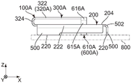
Referring to fig. 3 and 4, the antenna 100 of the present embodiment is formed of a single metal plate having a plurality of bent portions 222, 422, 502, 616, 626 and 722. The antenna 100 of the present embodiment forms a split ring resonator. Specifically, the antenna 100 is a discrete member formed by punching out a single metal plate and then bending it. More specifically, the antenna 100 of the present embodiment has a main body portion 200, a facing portion 300, a first feeding terminal 400, three second feeding terminals 500, and two reinforcing terminals 600. However, the present invention is not limited thereto. The number of the second feeding terminal 500 may be one or more. Similarly, the number of reinforcing terminals 600 may be one or more.
Referring to fig. 2, the main body portion 200 of the present embodiment constitutes an inductance of the antenna 100. The body portion 200 has a generally rectangular ring shape with four sides 202, 204, 206, and 208. The expression "ring shape" used herein includes not only a ring shape but also an elliptical ring shape and a polygonal ring shape. The side surfaces 202 and 204 are located at opposite ends of the main body portion 200 in the front-rear direction, respectively. More specifically, in the front-rear direction, the side 202 is located at the front end of the main body portion 200, and the side 204 is located at the rear end of the main body portion 200. In the present embodiment, the front-rear direction is the X direction. Specifically, forward is the negative X direction and backward is the positive X direction. The side surfaces 206 and 208 are located at opposite ends of the main body portion 200 in the left-right direction, respectively. More specifically, in the left-right direction, the side 206 is located at the left end of the main body portion 200, and the side 208 is located at the right end of the main body portion 200. In the present embodiment, the left-right direction is the Y direction. Specifically, the right is the positive Y direction, and the left is the negative Y direction. Referring to fig. 4 to 7, when the antenna 100 is mounted on the object 800, the outer edges of the three sides 204, 206, and 208 of the body portion 200 are fixed to the object 800. In contrast, when the antenna 100 is mounted on the object 800, the outer edge or the front edge of the side face 202 of the body portion 200 is not fixed to the object 800.
As shown in fig. 4, the main body portion 200 of the present embodiment has a plurality of fixing portions 220. The fixed portions 220 are arranged as mirror images of each other relative to the facing portion 300. In other words, the arrangement of the fixing portion 220 is symmetrical with respect to the facing portion 300. More specifically, the main body portion 200 has three fixing portions 220, and the fixing portions 220 are arranged as mirror images with respect to each other with respect to an imaginary line L parallel to the front-rear direction and passing through the center of the facing portion 300 in the left-right direction. However, the present invention is not limited thereto. The fixing portions 220 may be arranged not to be mirror images of each other with respect to the facing portion 300. If the fixed portions 220 are arranged as mirror images of each other with respect to the facing portion 300, the antenna 100 has the following advantages: when an unexpected external force is applied to the antenna 100, the applied external force is appropriately distributed to the fixing portion 220, thereby preventing the antenna 100 from being deformed. Accordingly, it is preferable that the arrangement of the fixing portion 220 is symmetrical with respect to the facing portion 300. As shown in fig. 1 and 3, each of the fixing portions 220 is a lower end of the antenna 100 in the up-down direction. In the present embodiment, the up-down direction is the Z direction. Specifically, upward is the positive Z direction, and downward is the negative Z direction.
As shown in fig. 2, the body portion 200 of the present embodiment is provided with a dividing line portion 210 having an opening 216. More specifically, the dividing line portion 210 is provided on a specific side 202 of the four sides 202, 204, 206, and 208 of the body portion 200. In other words, the body part 200 has a ring shape including the dividing line part 210, and the dividing line part 210 has the opening 216.
As shown in fig. 2, the dividing line part 210 is located at the front end of the antenna 100 in the front-rear direction. The dividing line part 210 extends in a predetermined direction. The split line portion 210 has a first end portion 212 and a second end portion 214. The first end portion 212 and the second end portion 214 are spaced apart from each other in a predetermined direction leaving an opening 216 therebetween. In the present embodiment, the predetermined direction is the Y direction. Specifically, in the present embodiment, the predetermined direction is also the left-right direction. However, the present invention is not limited thereto. The predetermined direction may be an arc direction that is arched in the front-rear direction.
As shown in fig. 2, in the predetermined direction, the first end portion 212 and the second end portion 214 of the present embodiment face each other across the opening 216 therebetween. Each of the first end portion 212 and the second end portion 214 surrounds the imaginary line L. The first end portion 212 is located on the left side of the second end portion 214 in the left-right direction.
As shown in fig. 2, the opening 216 of the present embodiment is a slit extending in the front-rear direction. The opening 216 is located at the same position in the predetermined direction as the imaginary line L.
Referring to fig. 2, the facing portion 300 of the present embodiment constitutes a capacitor of the antenna 100. Since the main body portion 200 constitutes the inductance of the antenna 100 as described above, the facing portion 300 and the main body portion 200 form an LC resonator circuit. The rear end of the facing portion 300 is not coupled with the body portion 200. The facing portion 300 is located between the side faces 202 and 204 of the main body portion 200 in the front-rear direction. The facing portion 300 is positioned between the sides 206 and 208 of the main body portion 200 in the left-right direction. The facing portion 300 includes a first facing portion 320 and a second facing portion 340. Specifically, the first facing portion 320 is provided on the first end portion 212, and the second facing portion 340 is provided on the second end portion 214.
As shown in fig. 2, the first facing portion 320 and the second facing portion 340 of the present embodiment are spaced apart from and face each other. More specifically, in the left-right direction, the first facing portion 320 and the second facing portion 340 are spaced apart from and face each other. Facing portion 300 is formed with interdigitated grooves 360 between first facing portion 320 and second facing portion 340.
As shown in fig. 2, the first facing portion 320 of the present embodiment has a comb-tooth shape. The first facing portion 320 extends from the first end portion 212 to be located inside the body portion 200. More specifically, the first facing portion 320 extends rearward in the front-rear direction from the first end portion 212 to be located inside the main body portion 200. The rear end of the first facing portion 320 is not coupled with the body portion 200. The first facing portion 320 is located on the left side of the second facing portion 340 in the left-right direction.
As shown in fig. 2, the second facing portion 340 of the present embodiment has a comb-tooth shape. The second facing portion 340 extends from the second end portion 214 to be located inside the body portion 200. More specifically. The second facing portion 340 extends rearward in the front-rear direction from the second end portion 214 to be located inside the main body portion 200. The rear end of the second facing portion 340 is not coupled with the body portion 200. The second facing portion 340 is located at the right side of the first facing portion 320 in the left-right direction.
As shown in fig. 5, when the antenna 100 is mounted on the object 800, the first feeding terminal 400 of the present embodiment is fixed on the object 800. More specifically, when the antenna 100 is mounted on the object 800, the first feeding terminal 400 is electrically connected to a feeding line (not shown) through a connection pad (not shown) of the object 800.
As shown in fig. 2, the first feeding terminal 400 is provided on the body portion 200. Specifically, the first feeding terminal 400 is provided on a specific side 202 providing the dividing line portion 210 among the four sides 202, 204, 206, and 208 of the body portion 200. Specifically, the first feed terminal 400 extends from a specific side 202 of the four sides 202, 204, 206, and 208 of the body portion 200.
As shown in fig. 4, on the body portion 200, the first feed terminal 400 is located between the first end portion 212 and any second feed terminal 500. On the body portion 200, the first feed terminal 400 is closer to the first end portion 212 than any of the second feed terminals 500. In other words, the first feeding terminal 400 is disposed on the body portion 200 such that a current path between the first feeding terminal 400 and the first end portion 212 is shorter than a current path between the first feeding terminal 400 and any of the second feeding terminals 500. The first feed terminal 400 is distant from any one of the first end portion 212 and the first facing portion 320. More specifically, the first feeding terminal 400 faces away from the left side of any one of the first end portion 212 and the first facing portion 320 in the left-right direction.
As shown in fig. 4, the shortest distance D1 between the first feeding terminal 400 and the first facing portion 320 is shorter than the shortest distance D2 between the first feeding terminal 400 and any of the second feeding terminals 500.
As shown in fig. 2 and 3, the first feeding terminal 400 of the present embodiment has a first portion 410 and a second portion 420.
As shown in fig. 2 and 3, the first portion 410 of the present embodiment extends from the body portion 200 in an inward direction that is directed toward the inside of the body portion 200 and intersects with a predetermined direction. In this embodiment, the inward direction is the positive X direction, or rearward. Specifically, the first portion 410 extends rearward from the main body portion 200 in the front-rear direction. The first portion 410 has an inwardly directed end 412. The end 412 of the first portion 410 is the back end of the first portion 410.
As shown in fig. 5, when the antenna 100 is mounted on the object 800, the second portion 420 of the present embodiment is fixed to the object 800. As shown in fig. 3, the second portion 420 extends from the end 412 of the first portion 410 in a crossing direction crossing the inward direction and the predetermined direction. In the present embodiment, the crossing direction is the Z direction. In other words, the crossing direction of the present embodiment is also the up-down direction. However, the present invention is not limited thereto. The crossing direction may be modified provided that it crosses both the inward direction and the predetermined direction. The second portion 420 extends downward in the up-down direction. The second section 420 has a first feeding terminal bent portion (bent portion) 422 at an upper end in an up-down direction thereof. As shown in fig. 4, the first feeding terminal bent portion 422 of the second section 420 is coupled with the end 412 of the first section 410 in the front-rear direction.
As shown in fig. 7, when the antenna 100 is mounted on the object 800, the second feeding terminal 500 of the present embodiment is mounted on the object 800. More specifically, when the antenna 100 is mounted on the object 800, the second feeding terminal 500 is electrically connected to the ground plane (not shown) through both the connection pad (not shown) and the fixing portion 220 of the object 800.
As shown in fig. 3 and 4, each of the second feeding terminals 500 of the present embodiment is provided on the main body portion 200. More specifically, the second feeding terminal 500 is provided on the sides 204, 206, and 208 of the four sides 202, 204, 206, and 208 of the body portion 200, respectively. Each of the second feeding terminals 500 extends downward from the body portion 200 in the up-down direction. Each of the two second feeding terminals 500 has a bent portion 222 at an upper end thereof in the up-down direction. The remaining one of the second feeding terminals 500 has a bent portion 502 at an upper end thereof in the up-down direction. The bent portion 502 of the remaining one of the second feeding terminals 500 is coupled with the side 204 of the body portion 200. The bent portion 222 of the second feeding terminal 500 is coupled with the sides 206 and 208 of the body portion 200, respectively.
As shown in fig. 6, when the antenna 100 is mounted on the object 800, each of the reinforcing terminals 600 of the present embodiment is fixed to the object 800. As shown in fig. 3, each of the reinforcing terminals 600 extends from the facing portion 300.
As shown in fig. 4, the reinforcing terminal 600 is disposed at a position away from the dividing line part 210. More specifically, the reinforcement terminal 600 faces rearward in the front-rear direction away from the dividing line part 210. The reinforcement terminal 600 faces away from either of the first end portion 212 and the second end portion 214. More specifically, the reinforcement terminal 600 faces away from any one of the first end portion 212 and the second end portion 214 in the front-rear direction. The reinforcement terminal 600 is disposed at a position facing away from the first feeding terminal 400. More specifically, the reinforcement terminal 600 faces away from the first feeding terminal 400 in the front-rear direction.
As shown in fig. 4, the reinforcing terminal 600 is closer to the rear end of the facing portion 300 than the dividing line portion 210 in the front-rear direction. The reinforcing terminal 600 is closer to the rear end of the facing portion 300 than any one of the first end portion 212 and the second end portion 214 in the front-rear direction. The reinforcing terminal 600 is closer to the rear end of the facing portion 300 than the first feeding terminal 400 in the front-rear direction. Specifically, the reinforcing terminal 600 is disposed around the rear end of the facing portion 300.
As shown in fig. 4, the reinforcing terminal 600 is closer to the side face 204 of the body portion 200 than the dividing line portion 210 in the front-rear direction. The reinforcing terminal 600 is closer to the side face 204 of the main body portion 200 than any one of the first end portion 212 and the second end portion 214 in the front-rear direction. The reinforcing terminal 600 is closer to the side 204 of the body portion 200 than the first feeding terminal 400 in the front-rear direction.
As shown in fig. 3, the reinforcing terminal 600 of the present embodiment includes a first reinforcing terminal 610 and a second reinforcing terminal 620.
As shown in fig. 3, the first reinforcing terminal 610 of the present embodiment extends from the first facing portion 320. More specifically, the first reinforcing terminal 610 extends leftward from the first facing portion 320 and then bends to extend downward. The first reinforcement terminal 610 is disposed on the left side of the second reinforcement terminal 620 in the left-right direction.
As shown in fig. 4, the first reinforcing terminal 610 is provided at a position away from the dividing line part 210. More specifically, the first reinforcement terminal 610 faces away from the dividing line part 210 in the front-rear direction. The first reinforcement terminal 610 faces away from the first end portion 212. More specifically, the first reinforcement terminal 610 faces away from the first end portion 212 in the front-rear direction. The first reinforcing terminal 610 is disposed at a position facing away from the first feeding terminal 400. More specifically, the first reinforcement terminal 610 faces away from the first feeding terminal 400 in the front-rear direction.
As shown in fig. 4, the first reinforcing terminal 610 is closer to the rear end of the first facing portion 320 than the dividing line portion 210 in the front-rear direction. The first reinforcing terminal 610 is closer to the rear end of the first facing portion 320 than the first end portion 212 in the front-rear direction. The first reinforcing terminal 610 is closer to the rear end of the first facing portion 320 than the first feeding terminal 400 in the front-rear direction. Specifically, the first reinforcement terminal 610 is disposed around the rear end of the first facing portion 320.
As shown in fig. 4, the first reinforcing terminal 610 is closer to the side face 204 of the main body portion 200 than the dividing line portion 210 in the front-rear direction. The first reinforcing terminal 610 is closer to the side 204 of the main body portion 200 than the first end portion 212 in the front-rear direction. The first reinforcing terminal 610 is closer to the side 204 of the body portion 200 than the first feeding terminal 400 in the front-rear direction.
As shown in fig. 4, the first reinforcing terminal 610 of the present embodiment has a first connection portion 612 and a second connection portion 615.
As shown in fig. 4, the first connecting portion 612 of the present embodiment extends from the first facing portion 320 in a first outward direction that is directed outward of the first facing portion 320 and intersects with the front-rear direction. More specifically, the first connecting portion 612 extends leftward in the left-right direction from the first facing portion 320. The first connecting portion 612 has an end 613 in a first outward direction. The end 613 of the first connecting portion 612 is the left end of the first connecting portion 612.
As shown in fig. 6, when the antenna 100 is mounted on the object 800, the second connection part 615 is fixed to the object 800. As shown in fig. 3 and 4, the second connecting portion 615 extends from the end 613 of the first connecting portion 612 in a direction intersecting the first outward direction and the front-rear direction. More specifically, the second connection portion 615 extends downward in the up-down direction. As shown in fig. 1, the second connecting portion 615 has a first reinforcing terminal bent portion (bent portion) 616 at an upper end in the up-down direction thereof. The first reinforcing terminal bent portion 616 of the second connection portion 615 is coupled with the end 613 of the first connection portion 612.
As described above, the first reinforcing terminal 610 extends downward from the first facing portion 320. With this structure, if an external force is applied to the first facing portion 320 from above in a state where the antenna 100 is mounted on the object 800, the applied external force is received by the object 800 through the first reinforcement terminal 610. Accordingly, the first facing portion 320 is effectively prevented from being deformed.
As shown in fig. 3, the second reinforcing terminal 620 of the present embodiment extends from the second facing portion 340. More specifically, the second reinforcing terminal 620 extends rightward from the second facing portion 340 and then bends to extend downward. The second reinforcement terminal 620 is located at the right side of the first reinforcement terminal 610 in the left-right direction.
As shown in fig. 4, the second reinforcing terminal 620 is located away from the dividing line portion 210. More specifically, the second reinforcement terminal 620 faces away from the dividing line part 210 in the front-rear direction. The second reinforcement terminal 620 is positioned away from the second end 214. More specifically, the second reinforcement terminal 620 faces away from the second end portion 214 in the front-rear direction.
As shown in fig. 4, the second reinforcing terminal 620 is closer to the rear end of the second facing portion 340 than the secant portion 210 in the front-rear direction. The second reinforcing terminal 620 is closer to the rear end of the second facing portion 340 than the second end portion 214 in the front-rear direction. Specifically, the second reinforcement terminal 620 is located around the rear end of the second facing portion 340.
As shown in fig. 4, the second reinforcing terminal 620 is closer to the side face 204 of the main body portion 200 than the dividing line portion 210 in the front-rear direction. The second reinforcing terminal 620 is closer to the side face 204 of the body portion 200 than the second end portion 214 in the front-rear direction.
As shown in fig. 4, the second reinforcing terminal 620 of the present embodiment has a first connecting portion 622 and a second connecting portion 625.
As shown in fig. 4, the first connecting portion 622 of the present embodiment extends from the second facing portion 340 in a second outward direction that is directed outward of the second facing portion 340 and intersects with the front-rear direction. More specifically, the first connecting portion 622 extends rightward in the left-right direction. The first connecting portion 622 has an end 623 in the second outward direction. The end 623 of the first connection portion 622 is the right end of the first connection portion 622.
Referring to fig. 3 and 6, when the antenna 100 is mounted on the object 800, the second connection part 625 of the present embodiment is fixed on the object 800. As shown in fig. 3, the second connecting portion 625 extends from the end 623 of the first connecting portion 622 in a direction intersecting the second outward direction and the front-rear direction. More specifically, the second connection portion 625 extends downward in the up-down direction. The second connecting portion 625 has a second reinforcing terminal bent portion (bent portion) 626 at an upper end in the up-down direction thereof. The second reinforcing terminal bent portion 626 of the second connection portion 625 is coupled with the end 623 of the first connection portion 622.
As described above, the second reinforcing terminal 620 extends downward from the second facing portion 340. With this structure, if an external force is applied to the second facing portion 340 from above in a state where the antenna 100 is mounted on the object 800, the applied external force is received by the object 800 through the second reinforcement terminal 620. Accordingly, the second facing portion 340 is effectively prevented from being deformed.
As shown in fig. 2 to 4, the antenna 100 of the present embodiment further includes an additional terminal 700.
As shown in fig. 5, when the antenna 100 is mounted on the object 800, the additional terminal 700 of the present embodiment is fixed on the object 800. When the additional terminal 700 is fixed to the object 800, the additional terminal 700 is not connected to any one of the feeder line and the ground plane of the object 800.
As shown in fig. 2, an additional terminal 700 is provided on the body portion 200. More specifically, the additional terminal 700 is provided on a specific side 202 providing the dividing line part 210 among the four sides 202, 204, 206, and 208 of the body part 200. Specifically, the additional terminal 700 extends from a specific side 202 of the four sides 202, 204, 206, and 208 of the body portion 200.
As shown in fig. 4, on the body portion 200, an additional terminal 700 is located between the second end portion 214 and any one of the second feeding terminals 500. On the body portion 200, the additional terminal 700 is closer to the second end portion 214 than any one of the second feeding terminals 500. The additional terminal 700 crosses the facing portion 300 and is opposite to the first feeding terminal 400. The additional terminal 700 is provided as a mirror image of the first feeding terminal 400 with respect to the facing portion 300. The additional terminal 700 is arranged as a mirror image of the first feeding terminal 400 with respect to the imaginary line L. However, the present invention is not limited thereto. The additional terminal 700 may be provided not to be a mirror image of the first feeding terminal 400 with respect to the facing portion 300. Similarly, the additional terminal 700 may be disposed not to be a mirror image of the first feeding terminal 400 with respect to the imaginary line L. The additional terminal 700 is disposed away from any one of the second end portion 214 and the second facing portion 340. More specifically, the additional terminal 700 faces away from any one of the second end portion 214 and the second facing portion 340 in the left-right direction.
As shown in fig. 4, the shortest distance D3 between the additional terminal 700 and the second facing portion 340 is shorter than the shortest distance D4 between the additional terminal 700 and any one of the second feeding terminals 500.
As shown in fig. 4, the additional terminal 700 is disposed at a position away from the reinforcing terminal 600. More specifically, the additional terminal 700 faces away from the reinforcement terminal 600 in the front-rear direction. The additional terminal 700 is farther away from the rear end of the facing portion 300 than the reinforcing terminal 600 in the front-rear direction. The additional terminal 700 is farther away from the rear end of the second facing portion 340 than the second reinforcing terminal 620 in the front-rear direction. The additional terminal 700 is farther away from the side 204 of the main body portion 200 than the reinforcing terminal 600 in the front-rear direction. The additional terminal 700 is farther away from the side 204 of the main body portion 200 than the second reinforcing terminal 620 in the front-rear direction.
As shown in fig. 2 and 3, the additional terminal 700 has the same structure as the first feeding terminal 400. More specifically, the additional terminal 700 has a first portion 710 and a second portion 720.
As shown in fig. 2 and 3, the first portion 710 of the present embodiment extends from the body portion 200 in an inward direction that is directed toward the inside of the body portion 200 and intersects with a predetermined direction. More specifically, the first portion 710 extends rearward from the main body portion 200 in the front-rear direction. The first portion 710 has an inwardly directed end 712. The end 712 of the first portion 710 is the back end of the first portion 710.
As shown in fig. 5, when the antenna 100 is mounted on the object 800, the second portion 720 of the present embodiment is fixed on the object 800. As shown in fig. 3, the second portion 720 extends from the end 712 of the first portion 710 in a crossing direction crossing the inward direction and the predetermined direction. More specifically, the second portion 720 extends downward in the up-down direction. The second portion 720 has an additional terminal bending portion (bending portion) 722 at the upper end in the up-down direction thereof. As shown in fig. 4, the additional terminal bent portion 722 of the second portion 720 is coupled with the end 712 of the first portion 710 in the front-rear direction.
[ second embodiment ]
As shown in fig. 12, the antenna 100A according to the second embodiment of the present invention may be mounted on an object 800. The antenna 100A according to the second embodiment of the present invention has a structure similar to that of the antenna 100 according to the foregoing first embodiment shown in fig. 1. The components of the antenna 100A shown in fig. 8 to 14 that are the same as the antenna 100 of the first embodiment are referred to by using the same reference numerals as the antenna 100 of the first embodiment. As for the direction and orientation in the present embodiment, the same expressions as those of the first embodiment will be used hereinafter.
As shown in fig. 9, the antenna 100A of the present embodiment is formed of a single metal plate having a plurality of bent portions 222, 324, 344, 422, 502, 616A, 626A, and 722. The antenna 100A of the present embodiment forms a split ring resonator. More specifically, as shown in fig. 10, the antenna 100A of the present embodiment has a main body portion 200, a facing portion 300A, a first feeding terminal 400, three second feeding terminals 500, and two reinforcing terminals 600A. However, the present invention is not limited thereto. The number of the second feeding terminal 500 may be one or more. Similarly, the number of the reinforcing terminals 600A may be one or more. The components of the antenna 100A have the same structure as the antenna 100 of the first embodiment except for the facing portion 300A and the reinforcing terminal 600A. Accordingly, detailed description about components other than the facing portion 300A and the reinforcing terminal 600A is omitted.
As understood from fig. 9, the facing portion 300A of the present embodiment constitutes a capacitor of the antenna 100A. Similar to the foregoing first embodiment, the main body portion 200 of the present embodiment constitutes the inductance of the antenna 100A. Thus, the facing portion 300A and the main body portion 200 form an LC resonator circuit. The rear end of the facing portion 300A is not coupled with the main body portion 200. The facing portion 300A is located between the side faces 202 and 204 of the main body portion 200 in the front-rear direction. The facing portion 300A is positioned between the side faces 206 and 208 of the main body portion 200 in the left-right direction. The facing portion 300A includes a first facing portion 320A and a second facing portion 340A. Specifically, the first facing portion 320A is disposed on the first end portion 212, and the second facing portion 340A is disposed on the second end portion 214.
As shown in fig. 9, the first and second facing portions 320A and 340A of the present embodiment are spaced apart from each other and face each other. More specifically, in the left-right direction, the first facing portion 320A and the second facing portion 340A are spaced apart from each other and face each other. Facing portion 300A has interdigitated grooves 380 formed between first facing portion 320A and second facing portion 340A.
As shown in fig. 8 and 10, the first facing portion 320A of the present embodiment has a comb-tooth shape. The first facing portion 320A extends from the first end portion 212 to be located inside the body portion 200. More specifically. The first facing portion 320A extends rearward from the first end portion 212 in the front-rear direction to be positioned inside the main body portion 200. The rear end of the first facing portion 320A is not coupled with the body portion 200. The first facing portion 320A is located on the left side of the second facing portion 340A in the left-right direction.
As shown in fig. 8 and 10, the first facing portion 320A of the present embodiment includes a first upper facing element 322, a first lower facing element 323, and a first facing-portion curved portion (curved portion) 324.
As shown in fig. 9, the first upper facing element 322 of the present embodiment has a comb-tooth shape. The first upper facing member 322 extends rearward from the first facing portion bent portion 324 in the front-rear direction. The rear end of the first upper facing member 322 is not coupled with the body portion 200. As shown in fig. 8, the first upper facing element 322 is located above the first lower facing element 323 in the up-down direction.
As shown in fig. 11, the first lower facing element 323 of the present embodiment has a comb-tooth shape. The first lower facing element 323 extends from the first end portion 212 to be located inside the body portion 200. More specifically, the first lower facing element 323 extends rearward in the front-rear direction from the first end portion 212 to be located inside the body portion 200. The rear end of the first lower facing element 323 is not coupled with the body portion 200.
As can be understood from fig. 8 to 11, when the antenna 100A is viewed in the up-down direction, the first upper facing element 322 and the first lower facing element 323 overlap each other. More specifically, when the antenna 100A is viewed in the up-down direction, the first upper facing element 322 and the first lower facing element 323 completely overlap each other. In other words, when the antenna 100A is viewed in the up-down direction, one of the first upper facing element 322 and the first lower facing element 323 completely hides the other.
As shown in fig. 13, the first facing portion bent portion 324 of the present embodiment has a lateral U-shaped cross section in a plane perpendicular to the left-right direction. The front end of the first facing portion bent portion 324 is the front end of the antenna 100A. As shown in fig. 10, first facing portion bent portion 324 connects first upper facing member 322 and first end portion 212 to each other. As shown in fig. 11, the first facing portion bent portion 324 is coupled with the first end portion 212 in the front-rear direction. As shown in fig. 9, the first facing portion bent portion 324 is coupled with the first upper facing member 322 in the front-rear direction.
As shown in fig. 8 and 10, the second facing portion 340A of the present embodiment has a comb-tooth shape. The second facing portion 340A extends from the second end portion 214 to be located inside the main body portion 200. More specifically, the second facing portion 340A extends rearward from the second end portion 214 in the front-rear direction to be located inside the main body portion 200. The rear end of the second facing portion 340A is not coupled with the body portion 200. The second facing portion 340A is located on the right side of the first facing portion 320A in the left-right direction.
As shown in fig. 8 and 10, the second facing portion 340A of the present embodiment is composed of a second upper facing member 342, a second lower facing member 343, and a second facing-portion curved portion (curved portion) 344.
As shown in fig. 9, the second upper facing element 342 of the present embodiment has a comb-tooth shape. The second upper facing member 342 extends rearward from the second facing portion bent portion 344 in the front-rear direction. The rear end of the second upper facing member 342 is not coupled with the body portion 200. As can be appreciated from fig. 8 and 10, second upper pair of elements 342 is located above second lower pair of elements 343 in the up-down direction.
As shown in fig. 11, the second lower pair of elements 343 of the present embodiment has a comb-tooth shape. Second lower pair of members 343 extends from second end portion 214 to be located inside body portion 200. More specifically, the second lower pair of members 343 extends rearward in the front-rear direction from the second end portion 214 to be located inside the main body portion 200. The rear end of the second lower pair of elements 343 is not coupled to the body portion 200.
As can be understood from fig. 8 to 11, when the antenna 100A is viewed in the up-down direction, the second upper pair of elements 342 and the second lower pair of elements 343 overlap each other. More specifically, when the antenna 100A is viewed in the up-down direction, the second upper-facing element 342 and the second lower-facing element 343 completely overlap each other. In other words, when the antenna 100A is viewed in the up-down direction, one of the second upper-facing element 342 and the second lower-facing element 343 completely hides the other.
Referring to fig. 8 and 10, the second facing-portion bent portion 344 of the present embodiment has a lateral U-shaped cross section in a plane perpendicular to the left-right direction. The front end of the second facing portion bent portion 344 is the front end of the antenna 100A. As can be understood from fig. 8 and 10, the second facing portion bent portion 344 couples the second upper facing member 342 and the second end portion 214 to each other. As shown in fig. 11, the second facing portion bent portion 344 is coupled with the second end 214 in the front-to-rear direction. As shown in fig. 9, the second facing-portion bent portion 344 is coupled with the second upper facing member 342 in the front-rear direction.
As shown in fig. 9, the first upper facing element 322 and the second upper facing element 342 of this embodiment are spaced apart from and face each other. More specifically, in the left-right direction, the first upper facing element 322 and the second upper facing element 342 are spaced apart from each other and face each other. Confronting portion 300A has interdigitated grooves 382 formed between first upper confronting element 322 and second upper confronting element 342.
As shown in fig. 11, the first 323 and second 343 lower facing elements of the present embodiment are spaced apart from each other and face each other. More specifically, in the left-right direction, the first lower facing element 323 and the second lower facing element 343 are spaced apart from each other and face each other. Facing portion 300A has interdigitated grooves 384 formed between first lower facing element 323 and second lower facing element 343.
As described above, facing portion 300A of the present embodiment includes a layer consisting of first upper facing element 322, second upper facing element 342, and interdigital groove 382, and another layer consisting of first lower facing element 323, second lower facing element 343, and interdigital groove 384. In other words, the facing portion 300A of the present embodiment has a double-layer structure. This structure enables the capacitor of the antenna 100A to have an increased capacitance without increasing the size of the facing portion 300A in the plane perpendicular to the up-down direction. The body portion 200 may have a smaller inductance if the capacitor of the antenna 100A has a larger capacitance under the condition that the antenna 100A has a constant resonance frequency. This means that the main body portion 200A of the antenna 100A has a smaller size in a plane perpendicular to the up-down direction. In other words, when antenna 100A is mounted on object 800, antenna 100A may occupy a smaller area on object 800.
As shown in fig. 14, when the antenna 100A is mounted on the object 800, each of the reinforcing terminals 600A of the present embodiment is fixed to the object 800. As shown in fig. 8, each of the reinforcing terminals 600A extends from the facing portion 300A.
As shown in fig. 11, the reinforcing terminal 600A is positioned away from the dividing line part 210. More specifically, the reinforcement terminal 600A is away from the dividing line part 210 in the front-rear direction. The reinforcement terminal 600A is located away from either of the first end portion 212 and the second end portion 214. More specifically, the reinforcement terminal 600A faces away from any one of the first end portion 212 and the second end portion 214 in the front-rear direction. The reinforcement terminal 600A is disposed at a position away from the first feeding terminal 400. More specifically, the reinforcement terminal 600A is distant from the first power feeding terminal 400 in the front-rear direction. The reinforcement terminal 600A faces away from the additional terminal 700. More specifically, the reinforcement terminal 600A faces away from the additional terminal 700 in the front-rear direction.
As shown in fig. 11, the reinforcing terminal 600A is closer to the rear end of the facing portion 300A than the dividing line portion 210 in the front-rear direction. The reinforcing terminal 600A is closer to the rear end of the facing portion 300A than either one of the first end portion 212 and the second end portion 214 in the front-rear direction. The reinforcement terminal 600A is closer to the rear end of the facing portion 300A than the first feeding terminal 400 in the front-rear direction. The reinforcing terminal 600A is closer to the rear end of the facing portion 300A than the additional terminal 700 in the front-rear direction. Specifically, the reinforcing terminal 600A is located around the rear end of the facing portion 300A.
As shown in fig. 11, the reinforcing terminal 600A is closer to the side face 204 of the main body portion 200 than the dividing line portion 210 in the front-rear direction. The reinforcing terminal 600A is closer to the side face 204 of the main body portion 200 than any one of the first end portion 212 and the second end portion 214 in the front-rear direction. The reinforcing terminal 600A is closer to the side 204 of the body portion 200 than the first feeding terminal 400 in the front-rear direction. The reinforcing terminal 600A is closer to the side 204 of the body portion 200 than the additional terminal 700 in the front-rear direction.
As shown in fig. 10 and 11, the reinforcing terminal 600A of the present embodiment includes a first reinforcing terminal 610A and a second reinforcing terminal 620A.
As shown in fig. 10 and 11, the first reinforcing terminal 610A of the present embodiment extends from the first facing portion 320A. More specifically, the first reinforcing terminal 610A extends leftward from the first facing portion 320A and then is bent to extend downward. The first reinforcement terminal 610A is located on the left side of the second reinforcement terminal 620A in the left-right direction.
As shown in fig. 10 and 11, the first reinforcing terminal 610A is provided at a position away from the dividing line part 210. More specifically, the first reinforcement terminal 610A faces away from the dividing line part 210 in the front-rear direction. The first reinforcement terminal 610A faces away from the first end portion 212. More specifically, the first reinforcement terminal 610A faces away from the first end portion 212 in the front-rear direction. The first reinforcement terminal 610A faces away from the first feeding terminal 400. More specifically, the first reinforcement terminal 610A faces away from the first feeding terminal 400 in the front-rear direction.
As shown in fig. 11, the first reinforcing terminal 610A is closer to the rear end of the first facing portion 320A than the split line portion 210 in the front-rear direction. The first reinforcing terminal 610A is closer to the rear end of the first facing portion 320A than the first end portion 212 in the front-rear direction. The first reinforcing terminal 610A is closer to the rear end of the first facing portion 320A than the first feeding terminal 400 in the front-rear direction. Specifically, the first reinforcement terminal 610A is located around the rear end of the first facing portion 320A.
As shown in fig. 11, the first reinforcing terminal 610A is closer to the side face 204 of the main body portion 200 than the dividing line portion 210 in the front-rear direction. The first reinforcing terminal 610A is closer to the side 204 of the main body portion 200 than the first end portion 212 in the front-rear direction. The first reinforcing terminal 610A is closer to the side 204 of the body portion 200 than the first feeding terminal 400 in the front-rear direction. The first reinforcing terminal 610A is closer to the side 204 of the body portion 200 than the additional terminal 700 in the front-rear direction.
As shown in fig. 11, the first reinforcing terminal 610A of the present embodiment is directly coupled with the first upper facing element 322. The first reinforcement terminal 610A of the present embodiment is not directly coupled with the first underlying element 323. Specifically, the first reinforcement terminal 610A is coupled only with the first upper facing element 322 located above the first lower facing element 323. The first reinforcement terminal 610A has a first connection portion 612A and a second connection portion 615A.
As shown in fig. 8, the first connecting portion 612A of the present embodiment extends from the first upper facing element 322 of the first facing portion 320A in a first outward direction that is directed outward of the first upper facing element 322 and intersects with the front-rear direction. More specifically, the first connecting portion 612A extends leftward in the left-right direction from the first upper facing element 322 of the first facing portion 320A. The first connecting portion 612A has an end 613A in the first outward direction. The end 613A of the first connecting portion 612A is the left end of the first connecting portion 612A.
As shown in fig. 14, when the antenna 100A is mounted on the object 800, the second connection part 615A of the present embodiment is fixed to the object 800. As shown in fig. 10, the second connecting portion 615A extends from the end 613A of the first connecting portion 612A in a direction intersecting the first outward direction and the front-rear direction. More specifically, as shown in fig. 8, the second connection portion 615A extends downward in the up-down direction. The second connecting portion 615A has a first reinforcing terminal bent portion (bent portion) 616A at an upper end thereof in the up-down direction. The first reinforcing terminal bent portion 616A of the second connection portion 615A is coupled with the end 613A of the first connection portion 612A.
As described above, the first reinforcing terminal 610A extends downward from the first upper facing element 322. With this structure, if an external force is applied to the first upper facing element 322 from above in a state where the antenna 100A is mounted on the object 800, the applied external force is received by the object 800 through the first reinforcement terminal 610A. Accordingly, the first upper facing member 322 is effectively prevented from being deformed.
As shown in fig. 10 and 11, the second reinforcing terminal 620A of the present embodiment extends from the second facing portion 340A. More specifically, the second reinforcement terminal 620A extends rightward from the second facing portion 340A and then is bent to extend downward. The second reinforcement terminal 620A is located on the right side of the first reinforcement terminal 610A in the left-right direction.
As shown in fig. 11, the second reinforcing terminal 620A is provided at a position away from the dividing line part 210. More specifically, the second reinforcement terminal 620A faces away from the dividing line part 210 in the front-rear direction. The second reinforcement terminal 620A faces away from the second end portion 214. More specifically, the second reinforcement terminal 620A is positioned away from the second end portion 214 in the front-rear direction. The second reinforcement terminal 620A faces away from the additional terminal 700. More specifically, the second reinforcement terminal 620A faces away from the additional terminal 700 in the front-rear direction.
As shown in fig. 11, the second reinforcing terminal 620A is closer to the rear end of the second facing portion 340A than the dividing line portion 210 in the front-rear direction. The second reinforcing terminal 620A is closer to the rear end of the second facing portion 340A than the second end portion 214 in the front-rear direction. The second reinforcing terminal 620A is closer to the rear end of the second facing portion 340A than the additional terminal 700 in the front-rear direction. Specifically, the second reinforcement terminal 620A is located around the rear end of the second facing portion 340A.
As shown in fig. 11, the second reinforcing terminal 620A is closer to the side face 204 of the body portion 200 than the dividing line portion 210 in the front-rear direction. The second reinforcing terminal 620A is closer to the side face 204 of the body portion 200 than the second end portion 214 in the front-rear direction. The second reinforcing terminal 620A is closer to the side 204 of the body portion 200 than the additional terminal 700 in the front-rear direction.
As shown in fig. 11, the second reinforcement terminal 620A of the present embodiment is directly coupled with the second upper facing element 342. The second reinforcement terminal 620A of the present embodiment is not directly coupled with the second lower pair of elements 343. Specifically, the second reinforcement terminal 620A is coupled only with the second upper-facing element 342 located above the second lower-facing element 343. The second reinforcing terminal 620A has a first connection portion 622A and a second connection portion 625A.
As shown in fig. 9, the first connecting portion 622A of the present embodiment extends from the second upper facing element 342 of the second facing portion 340A in a second outward direction that is directed outward of the second upper facing element 342 and intersects with the front-rear direction. More specifically, the first connecting portion 622A extends rightward in the left-right direction from the second upper facing element 342 of the second facing portion 340A. The first connecting portion 622A has an end 623A in the second outward direction. The end 623A of the first connection portion 622A is the right end of the first connection portion 622A.
As shown in fig. 14, when the antenna 100A is mounted on the object 800, the second connecting portion 625A of the present embodiment is fixed on the object 800. As will be understood from fig. 10 and 11, the second connecting portion 625A extends from the end 623A of the first connecting portion 622A in a direction intersecting the second outward direction and the front-rear direction. More specifically, the second connecting portion 625A extends downward in the up-down direction. As shown in fig. 9, the second connecting portion 625A has a second reinforcing terminal bent portion (bent portion) 626A at an upper end in an upper-lower direction thereof. The second reinforcing terminal bent portion 626A of the second connection portion 625A is coupled with the end 623A of the first connection portion 622A.
As described above, the second reinforcing terminal 620A extends downward from the second upper facing member 342. With this structure, if an external force is applied to the second upper facing element 342 from above in a state where the antenna 100A is mounted on the object 800, the applied external force is received by the object 800 through the second reinforcing terminal 620A. Accordingly, the second upper facing member 342 is effectively prevented from being deformed.
Although the present invention has been specifically explained above with reference to the embodiments, the present invention is not limited thereto, and is susceptible to various modifications and alternative forms.
Although the additional terminal 700 of the antennas 100, 100A of the foregoing embodiments has the same structure as the first feeding terminal 400, the present invention is not limited thereto. The additional terminal 700 may have a shape and size different from those of the first feeding terminal 400. The resonant frequency of the antenna 100, 100A may be changed by modifying one or more of the location, shape, and size of the additional terminal 700. It is easier to design the antennas 100, 100A compared to a design of an antenna without the above-described configuration, the antennas 100, 100A having a configuration such that the first feeding terminal 400 and the additional terminal 700 have the same shape and size while the arrangement thereof is symmetrical with respect to the facing portions 300, 300A. Accordingly, the antennas 100, 100A preferably have the aforementioned configuration.
Although the facing portion 300A of the antenna 100A of the foregoing second embodiment has a double-layer structure, the present invention is not limited thereto. The facing portion 300A may have a three-layer or more structure. Although the antenna 100A of the foregoing second embodiment is configured such that the first upper facing element 322 is located above the first lower facing element 323 and the second upper facing element 342 is located above the second lower facing element 343, the present invention is not limited thereto. In particular, antenna 100A may be modified such that first upper facing element 322 is located below first lower facing element 323 and second upper facing element 342 is located below second lower facing element 343.
While there has been described what are believed to be the preferred embodiments of the invention, those skilled in the art will recognize that other and further modifications may be made thereto without departing from the spirit of the invention, and it is intended to claim all such embodiments as fall within the true scope of the invention.
Claims (12)
1. An object-mountable antenna, characterized by:
the antenna forms a split ring resonator structure;
the antenna has a body portion, a facing portion, a first feed terminal, a second feed terminal, and at least one reinforcing terminal;
the body portion has a ring shape including a dividing line portion;
the dividing line portion extends in a predetermined direction;
the dividing line portion having an opening, a first end portion and a second end portion;
the first end portion and the second end portion being spaced apart from each other in a predetermined direction leaving the opening therebetween;
the facing portion includes a first facing portion and a second facing portion;
the first facing portion is disposed on the first end portion;
the second facing portion is disposed on the second end portion;
the first and second facing portions being spaced apart from and facing each other;
each of the first and second feeding terminals is provided on the main body portion;
each of the first and second feed terminals is fixed to the object when the antenna is mounted on the object;
the at least one reinforcement terminal is disposed at a position away from the dividing line part;
the at least one reinforcement terminal extends from the facing portion; and
the at least one reinforcement terminal is secured to the object when the antenna is mounted on the object.
2. The antenna of claim 1, wherein:
the first facing portion extending from the first end portion to be disposed inside the body portion; and
the second facing portion extends from the second end portion to be disposed inside the body portion.
3. The antenna of claim 1, wherein:
the at least one reinforcement terminal includes a first reinforcement terminal and a second reinforcement terminal;
the first reinforcement terminal extends from the first facing portion; and
the second reinforcement terminal extends from the second facing portion.
4. The antenna of claim 1, wherein:
the body portion has a generally rectangular ring shape with four sides; and
the dividing line portion is provided on a specific one of the four sides.
5. The antenna of claim 1, wherein:
the antenna further has an additional terminal;
the additional terminal is provided on the main body portion;
the additional terminal is fixed to the object when the antenna is mounted on the object;
on the main body portion, the additional terminal is closer to the second end portion than the second feeding terminal; and
the first feed terminal is closer to the first end portion than the second feed terminal is on the main body portion.
6. An antenna according to claim 5, wherein the shortest distance between the additional terminal and the second facing portion is shorter than the shortest distance between the additional terminal and the second feed terminal.
7. The antenna of claim 5, wherein:
the first feed terminal faces away from any one of the first end portion and the first facing portion; and
the additional terminal faces away from any one of the second end portion and the second facing portion.
8. The antenna of claim 7, wherein:
each of the first feed terminal and the additional terminal has a first portion and a second portion;
the first portion extends from the body portion in an inner direction;
the inner direction is directed towards the interior of the body portion;
the inner direction intersects with a predetermined direction;
the first portion has an end in an inner direction;
the second portion extending in a cross direction from the end of the first portion;
the crossing direction crosses both the internal direction and the predetermined direction; and
the second portion is secured to the object when the antenna is mounted on the object.
9. The antenna of claim 5, wherein:
the body portion has a generally rectangular ring shape with four sides; and
the dividing line portion is provided on a specific one of the four side surfaces.
10. The antenna of claim 9, wherein the additional terminal extends from a particular one of the four sides.
11. The antenna of claim 1, wherein:
each of the first facing portion and the second facing portion has a comb-tooth shape; and
the facing portion is formed with an interdigital groove between the first facing portion and the second facing portion.
12. The antenna of claim 1, wherein the antenna is formed from a single metal plate having a plurality of curved portions.
Applications Claiming Priority (2)
| Application Number | Priority Date | Filing Date | Title |
|---|---|---|---|
| JP2019039457A JP7216577B2 (en) | 2019-03-05 | 2019-03-05 | antenna |
| JP2019-039457 | 2019-03-05 |
Publications (2)
| Publication Number | Publication Date |
|---|---|
| CN111668586A CN111668586A (en) | 2020-09-15 |
| CN111668586B true CN111668586B (en) | 2022-04-19 |
Family
ID=69156321
Family Applications (1)
| Application Number | Title | Priority Date | Filing Date |
|---|---|---|---|
| CN202010052370.5A Active CN111668586B (en) | 2019-03-05 | 2020-01-17 | Antenna with a shield |
Country Status (6)
| Country | Link |
|---|---|
| US (1) | US11101563B2 (en) |
| EP (1) | EP3706244B1 (en) |
| JP (1) | JP7216577B2 (en) |
| KR (1) | KR102183917B1 (en) |
| CN (1) | CN111668586B (en) |
| TW (1) | TWI730576B (en) |
Families Citing this family (7)
| Publication number | Priority date | Publication date | Assignee | Title |
|---|---|---|---|---|
| JP7404031B2 (en) | 2019-10-29 | 2023-12-25 | 日本航空電子工業株式会社 | antenna |
| EP3817139A1 (en) * | 2019-10-29 | 2021-05-05 | Japan Aviation Electronics Industry, Limited | Antenna |
| JP7437143B2 (en) * | 2019-12-05 | 2024-02-22 | 日本航空電子工業株式会社 | antenna |
| USD951761S1 (en) * | 2020-10-27 | 2022-05-17 | Mafi Ab | Fastening device |
| USD944633S1 (en) * | 2020-11-25 | 2022-03-01 | Mafi Ab | Fastening device |
| JP2022108977A (en) | 2021-01-14 | 2022-07-27 | 日本航空電子工業株式会社 | Antenna member and assembly |
| JP1701515S (en) * | 2021-03-17 | 2021-12-06 |
Citations (8)
| Publication number | Priority date | Publication date | Assignee | Title |
|---|---|---|---|---|
| EP1313165A2 (en) * | 2001-11-15 | 2003-05-21 | Filtronic LK Oy | Method of manufacturing an internal antenna, and antenna element |
| CN101572353A (en) * | 2008-04-28 | 2009-11-04 | 鸿富锦精密工业(深圳)有限公司 | Solid antenna |
| EP2242144A2 (en) * | 2008-01-08 | 2010-10-20 | ACE Technologies Corporation | Multi-band internal antenna |
| EP3001503A1 (en) * | 2014-03-13 | 2016-03-30 | Huawei Device Co., Ltd. | Antenna and terminal |
| CN106299675A (en) * | 2015-05-29 | 2017-01-04 | 深圳富泰宏精密工业有限公司 | Antenna structure and apply the radio communication device of this antenna structure |
| CN206349509U (en) * | 2016-12-23 | 2017-07-21 | 金卡智能集团股份有限公司 | A kind of FIPA antennas applied to wireless gas meter |
| WO2018089947A1 (en) * | 2016-11-14 | 2018-05-17 | Dockon Ag | Compound loop antenna system with isolation frequency agility |
| CN207938801U (en) * | 2018-02-01 | 2018-10-02 | 惠州市泰信精密部件有限公司 | A kind of ultrastability antenna for mobile phone |
Family Cites Families (29)
| Publication number | Priority date | Publication date | Assignee | Title |
|---|---|---|---|---|
| GB0319211D0 (en) | 2003-08-15 | 2003-09-17 | Koninkl Philips Electronics Nv | Antenna arrangement and a module and a radio communications apparatus having such an arrangement |
| JP3790249B2 (en) * | 2004-01-13 | 2006-06-28 | 株式会社東芝 | Loop antenna and wireless communication device equipped with loop antenna |
| JP2007221774A (en) | 2006-01-23 | 2007-08-30 | Yokowo Co Ltd | Plane type antenna |
| US8866691B2 (en) * | 2007-04-20 | 2014-10-21 | Skycross, Inc. | Multimode antenna structure |
| US8836439B2 (en) * | 2007-10-12 | 2014-09-16 | Los Alamos National Security Llc | Dynamic frequency tuning of electric and magnetic metamaterial response |
| KR20090111056A (en) * | 2008-04-21 | 2009-10-26 | 주식회사 케이티테크 | Multi-band antenna for portable device and portable device using the same |
| CN201294259Y (en) * | 2008-07-22 | 2009-08-19 | 比亚迪股份有限公司 | Built-in double-frequency mobile phone antenna |
| CN101651253B (en) | 2008-08-11 | 2014-09-10 | 深圳富泰宏精密工业有限公司 | Dual-band antenna and wireless communication device using same |
| TWM368906U (en) * | 2009-05-15 | 2009-11-11 | Mag Layers Scient Technics Co | Capacitance coupling structure for loop antenna |
| US8593367B2 (en) | 2010-12-10 | 2013-11-26 | Blackberry Limited | Modified ground plane (MGP) approach to improving antenna self-matching and bandwidth |
| CN103620870B (en) | 2011-06-23 | 2017-02-15 | 加利福尼亚大学董事会 | Electrically small vertical split-ring resonator antennas |
| KR101919785B1 (en) * | 2012-04-23 | 2018-11-19 | 엘지전자 주식회사 | Mobile terminal |
| US9748662B2 (en) * | 2012-11-12 | 2017-08-29 | Nec Corporation | Antenna and wireless communication device |
| US9093750B2 (en) * | 2013-09-12 | 2015-07-28 | Laird Technologies, Inc. | Multiband MIMO vehicular antenna assemblies with DSRC capabilities |
| JP6508207B2 (en) | 2014-07-10 | 2019-05-08 | 日本電気株式会社 | Antenna, antenna array and wireless communication device |
| JP6077507B2 (en) * | 2014-09-19 | 2017-02-08 | Necプラットフォームズ株式会社 | Antenna and wireless communication device |
| CN204375915U (en) | 2014-11-10 | 2015-06-03 | 瑞声科技(南京)有限公司 | Multiband antenna |
| TWI662741B (en) * | 2015-01-23 | 2019-06-11 | 群邁通訊股份有限公司 | Antenna structure and wireless communication device having the same |
| JP6606871B2 (en) | 2015-06-04 | 2019-11-20 | 日本電気株式会社 | Antenna and wireless communication device |
| US10811755B2 (en) * | 2016-04-29 | 2020-10-20 | Commscope Technologies Llc | Microstrip capacitors with complementary resonator structures |
| JP6659519B2 (en) * | 2016-11-02 | 2020-03-04 | 株式会社東芝 | Antenna device |
| CN206947521U (en) * | 2017-06-17 | 2018-01-30 | 上海守远通讯科技有限公司 | Internet of Things antenna and the shared bicycle with the antenna |
| CN112204816B (en) * | 2018-04-27 | 2023-09-05 | 日本航空电子工业株式会社 | Conductor, antenna and communication device |
| JP6897989B2 (en) * | 2019-01-04 | 2021-07-07 | Necプラットフォームズ株式会社 | Antenna device and wireless device |
| JP7216576B2 (en) * | 2019-03-05 | 2023-02-01 | 日本航空電子工業株式会社 | antenna |
| JP7196007B2 (en) * | 2019-04-17 | 2022-12-26 | 日本航空電子工業株式会社 | antenna |
| JP7196008B2 (en) * | 2019-04-17 | 2022-12-26 | 日本航空電子工業株式会社 | antenna |
| JP7414415B2 (en) * | 2019-06-27 | 2024-01-16 | 日本航空電子工業株式会社 | Intermediate products for antennas and opposing parts used for them |
| JP7414414B2 (en) * | 2019-06-27 | 2024-01-16 | 日本航空電子工業株式会社 | antenna |
-
2019
- 2019-03-05 JP JP2019039457A patent/JP7216577B2/en active Active
-
2020
- 2020-01-02 TW TW109100032A patent/TWI730576B/en active
- 2020-01-08 US US16/736,984 patent/US11101563B2/en active Active
- 2020-01-09 EP EP20150935.3A patent/EP3706244B1/en active Active
- 2020-01-15 KR KR1020200005208A patent/KR102183917B1/en active IP Right Grant
- 2020-01-17 CN CN202010052370.5A patent/CN111668586B/en active Active
Patent Citations (8)
| Publication number | Priority date | Publication date | Assignee | Title |
|---|---|---|---|---|
| EP1313165A2 (en) * | 2001-11-15 | 2003-05-21 | Filtronic LK Oy | Method of manufacturing an internal antenna, and antenna element |
| EP2242144A2 (en) * | 2008-01-08 | 2010-10-20 | ACE Technologies Corporation | Multi-band internal antenna |
| CN101572353A (en) * | 2008-04-28 | 2009-11-04 | 鸿富锦精密工业(深圳)有限公司 | Solid antenna |
| EP3001503A1 (en) * | 2014-03-13 | 2016-03-30 | Huawei Device Co., Ltd. | Antenna and terminal |
| CN106299675A (en) * | 2015-05-29 | 2017-01-04 | 深圳富泰宏精密工业有限公司 | Antenna structure and apply the radio communication device of this antenna structure |
| WO2018089947A1 (en) * | 2016-11-14 | 2018-05-17 | Dockon Ag | Compound loop antenna system with isolation frequency agility |
| CN206349509U (en) * | 2016-12-23 | 2017-07-21 | 金卡智能集团股份有限公司 | A kind of FIPA antennas applied to wireless gas meter |
| CN207938801U (en) * | 2018-02-01 | 2018-10-02 | 惠州市泰信精密部件有限公司 | A kind of ultrastability antenna for mobile phone |
Also Published As
| Publication number | Publication date |
|---|---|
| US20200287269A1 (en) | 2020-09-10 |
| KR102183917B1 (en) | 2020-11-27 |
| EP3706244A1 (en) | 2020-09-09 |
| TW202034578A (en) | 2020-09-16 |
| EP3706244B1 (en) | 2022-03-16 |
| KR20200106819A (en) | 2020-09-15 |
| JP7216577B2 (en) | 2023-02-01 |
| US11101563B2 (en) | 2021-08-24 |
| CN111668586A (en) | 2020-09-15 |
| TWI730576B (en) | 2021-06-11 |
| JP2020145542A (en) | 2020-09-10 |
Similar Documents
| Publication | Publication Date | Title |
|---|---|---|
| CN111668586B (en) | Antenna with a shield | |
| CN111668587B (en) | Antenna with a shield | |
| US11251515B2 (en) | Antenna | |
| US11380997B2 (en) | Antenna | |
| US11063360B2 (en) | Antenna | |
| US11417957B2 (en) | Antenna | |
| CN220674000U (en) | Circuit board assembly and electronic equipment with same | |
| WO2021153435A1 (en) | Connector, connector module, and electronic equipment | |
| US11777217B2 (en) | Antenna member and assembly | |
| WO2023286664A1 (en) | Connector, and electronic device | |
| US20220029269A1 (en) | Split ring resonator and communication device |
Legal Events
| Date | Code | Title | Description |
|---|---|---|---|
| PB01 | Publication | ||
| PB01 | Publication | ||
| SE01 | Entry into force of request for substantive examination | ||
| SE01 | Entry into force of request for substantive examination | ||
| GR01 | Patent grant | ||
| GR01 | Patent grant |