CN111663506A - An interceptor for intercepting floating garbage in water - Google Patents
An interceptor for intercepting floating garbage in water Download PDFInfo
- Publication number
- CN111663506A CN111663506A CN202010626751.XA CN202010626751A CN111663506A CN 111663506 A CN111663506 A CN 111663506A CN 202010626751 A CN202010626751 A CN 202010626751A CN 111663506 A CN111663506 A CN 111663506A
- Authority
- CN
- China
- Prior art keywords
- frame
- outer tube
- water
- hemp rope
- interceptor
- Prior art date
- Legal status (The legal status is an assumption and is not a legal conclusion. Google has not performed a legal analysis and makes no representation as to the accuracy of the status listed.)
- Granted
Links
Images


Classifications
-
- E—FIXED CONSTRUCTIONS
- E02—HYDRAULIC ENGINEERING; FOUNDATIONS; SOIL SHIFTING
- E02B—HYDRAULIC ENGINEERING
- E02B15/00—Cleaning or keeping clear the surface of open water; Apparatus therefor
- E02B15/04—Devices for cleaning or keeping clear the surface of open water from oil or like floating materials by separating or removing these materials
- E02B15/08—Devices for reducing the polluted area with or without additional devices for removing the material
- E02B15/0807—Devices for reducing the polluted area with or without additional devices for removing the material with stabilising elements
-
- E—FIXED CONSTRUCTIONS
- E02—HYDRAULIC ENGINEERING; FOUNDATIONS; SOIL SHIFTING
- E02B—HYDRAULIC ENGINEERING
- E02B15/00—Cleaning or keeping clear the surface of open water; Apparatus therefor
- E02B15/04—Devices for cleaning or keeping clear the surface of open water from oil or like floating materials by separating or removing these materials
- E02B15/08—Devices for reducing the polluted area with or without additional devices for removing the material
- E02B15/0842—Devices for reducing the polluted area with or without additional devices for removing the material adapted to be towed for operation
-
- E—FIXED CONSTRUCTIONS
- E02—HYDRAULIC ENGINEERING; FOUNDATIONS; SOIL SHIFTING
- E02B—HYDRAULIC ENGINEERING
- E02B15/00—Cleaning or keeping clear the surface of open water; Apparatus therefor
- E02B15/04—Devices for cleaning or keeping clear the surface of open water from oil or like floating materials by separating or removing these materials
- E02B15/10—Devices for removing the material from the surface
Landscapes
- Engineering & Computer Science (AREA)
- General Engineering & Computer Science (AREA)
- Environmental & Geological Engineering (AREA)
- Mechanical Engineering (AREA)
- Civil Engineering (AREA)
- Structural Engineering (AREA)
- Cleaning Or Clearing Of The Surface Of Open Water (AREA)
Abstract
本发明公开了一种用于拦截水中浮游垃圾的拦截器,包括漂浮在水面之上的框架,在所述框架的内侧设置有多根支撑轴,在所述支撑轴上装配有一可回转的外管,所述外管和所述支撑轴之间配合有轴承,在所述外管的外壁处设置有多个插孔,在所述外管的外壁处设置有多个分隔盘,相邻分隔盘之间至少设置一个所述插孔,所述外管的一端设置有一从动齿轮,在所述框架的外侧插入有一转轴,所述转轴和所述框架之间配合有第一轴承;本发明中,采用沉入水中的麻绳作为载体,配合捕获装置可以水中捕获浮游在水中的垃圾袋等杂物。
The invention discloses an interceptor for intercepting floating garbage in water, comprising a frame floating on the water surface, a plurality of support shafts are arranged on the inner side of the frame, and a rotatable outer shaft is assembled on the support shaft A bearing is fitted between the outer tube and the support shaft, a plurality of insertion holes are arranged at the outer wall of the outer tube, and a plurality of partition discs are arranged at the outer wall of the outer tube, and adjacent partitions are arranged. At least one of the insertion holes is arranged between the discs, a driven gear is arranged at one end of the outer tube, a rotating shaft is inserted into the outer side of the frame, and a first bearing is matched between the rotating shaft and the frame; the present invention In the water, the hemp rope submerged in the water is used as the carrier, and the garbage bags and other debris floating in the water can be captured in the water with the capture device.
Description
技术领域technical field
本发明涉及一种用于拦截水中浮游垃圾的拦截器。The invention relates to an interceptor for intercepting floating garbage in water.
背景技术Background technique
河道是我们生活中较为常见的一种生态结构,五水共治的实施,针对河道环境提出了较为严格的要求。水体发臭的原因较多,垃圾过多是其发臭的一个原因之一,部分轻质量的垃圾漂浮在水面之上,部分潜入水中随着河水的流动而流动;漂浮在水面上的垃圾容易打捞捕获,而潜入水中的垃圾则非常难以捕获。只能等待后期清淤的时候进行清理。River is a common ecological structure in our life. The implementation of five water co-governance has put forward stricter requirements for the river environment. There are many reasons for the odor of water bodies. Excessive garbage is one of the reasons for the odor. Some light garbage floats on the water surface, and some submerge into the water and flow with the flow of the river; the garbage floating on the water surface is easy to Salvage to catch, while submerged litter is very difficult to catch. It can only be cleaned up when the dredging is done later.
为此,我们设计了一种可以漂浮在河道内,实现河道内的浮游垃圾的拦截的用于拦截水中浮游垃圾的拦截器。To this end, we designed an interceptor for intercepting floating garbage in the water, which can float in the river and realize the interception of floating garbage in the river.
发明内容SUMMARY OF THE INVENTION
本发明所要解决的技术问题是提供一种可以漂浮在河道内,实现河道内的浮游垃圾的拦截的用于拦截水中浮游垃圾的拦截器。The technical problem to be solved by the present invention is to provide an interceptor for intercepting floating garbage in water, which can float in the river channel and realize the interception of floating garbage in the river channel.
本发明是通过以下技术方案来实现的:The present invention is achieved through the following technical solutions:
一种用于拦截水中浮游垃圾的拦截器,包括漂浮在水面之上的框架,在所述框架的内侧设置有多根支撑轴,在所述支撑轴上装配有一可回转的外管,所述外管和所述支撑轴之间配合有轴承,在所述外管的外壁处设置有多个插孔,在所述外管的外壁处设置有多个分隔盘,相邻分隔盘之间至少设置一个所述插孔,所述外管的一端设置有一从动齿轮,在所述框架的外侧插入有一转轴,所述转轴和所述框架之间配合有第一轴承,所述转轴插入至框架内侧的那一端设置有主动齿轮,所述主动齿轮与所述齿轮之间啮合,所述主动齿轮和从动齿轮的传动比为N:1,及主动齿轮旋转N圈,从动齿轮旋转圈,通过所述插孔安插有麻绳,在所述麻绳上装配有多个捕获浮游垃圾用的捕获装置,在所述框架的外侧旋入有螺丝,所述螺丝旋入后抵住所述从动齿轮,此时所述外管被固定;在所述框架的上下侧面处均焊接有纵向的加强杆,下方的所述加强杆的底部设置有浮力箱,所述浮力箱的上端设置有进出水用的通孔,在通孔内旋入有密封塞;前后相邻的框架之间配合有连杆,连杆的两端均设置有螺栓,螺栓穿过框架后配合有螺母;在所述框架的顶部安装有吊环。上述结构中,通过浮力箱,让框架保持在水面之上,通过旋转外管,实现麻绳的放松和卷绕。An interceptor for intercepting floating garbage in water, comprising a frame floating on the water surface, a plurality of support shafts are arranged on the inner side of the frame, a rotatable outer tube is assembled on the support shaft, and the A bearing is fitted between the outer tube and the support shaft, a plurality of insertion holes are arranged at the outer wall of the outer tube, a plurality of partition discs are arranged at the outer wall of the outer tube, and at least A said socket is provided, a driven gear is provided at one end of the outer tube, a rotating shaft is inserted into the outer side of the frame, a first bearing is fitted between the rotating shaft and the frame, and the rotating shaft is inserted into the frame The inner end is provided with a driving gear, the driving gear meshes with the gear, the transmission ratio of the driving gear and the driven gear is N:1, and the driving gear rotates N circles, and the driven gear rotates circles, A hemp rope is inserted through the jack, a plurality of capturing devices for capturing floating garbage are assembled on the hemp rope, and screws are screwed into the outer side of the frame, and the screws are screwed in to resist the driven Gear, the outer tube is fixed at this time; longitudinal reinforcement rods are welded on the upper and lower sides of the frame, a buoyancy box is provided at the bottom of the reinforcement rod below, and the upper end of the buoyancy box is provided with water inlet and outlet A sealing plug is screwed into the through hole; connecting rods are fitted between the front and rear adjacent frames, bolts are provided at both ends of the connecting rods, and nuts are fitted after the bolts pass through the frame; A lifting ring is installed on the top of the . In the above structure, the buoyancy box is used to keep the frame above the water surface, and the hemp rope can be loosened and wound by rotating the outer tube.
优选地,N=10~20。Preferably, N=10~20.
优选地,所述捕获装置包括一个插杆,插杆的一端设置有倒刺部,所述插杆的另一端设置有端头,在端头内卡设有橡胶材质的内柱体,内柱体的局部延伸至所述端头的外部,在所述内柱体内设置有塑料材质的毛刺杆,所述毛刺杆远离所述内柱体的那一端注塑形成一个V字形的钩部;所述插杆插入至麻绳的缝隙处,所述倒刺部在插入缝隙处后钩住麻绳;捕获装置是可灵活的与麻绳之间进行安装的,安装数量,安装位置,安装间隔等都是可以调整的。无规则的布置,让麻绳在水中可以有效的捕获浮游的垃圾;捕获装置可拆卸,方便更换和维护。Preferably, the capturing device includes an insertion rod, one end of the insertion rod is provided with a barb, the other end of the insertion rod is provided with an end head, and an inner cylinder of rubber material is clamped in the end head, and the inner cylinder is A part of the body extends to the outside of the end head, a burr rod made of plastic material is arranged in the inner cylinder, and the end of the burr rod away from the inner cylinder is injection-molded to form a V-shaped hook; the The insertion rod is inserted into the gap of the hemp rope, and the barb part hooks the hemp rope after being inserted into the gap; the capturing device can be flexibly installed between the hemp rope, the number of installations, the installation position, the installation interval, etc. can be adjusted. The irregular arrangement allows the hemp rope to effectively capture floating garbage in the water; the capture device is detachable for easy replacement and maintenance.
优选地,所述内柱体的直径向着远离端头的方向逐渐缩小;内柱体的直径逐渐缩小,使得内柱体远离端头的那一端的转动能力增强,使得毛刺杆可以小幅度的移动,避免伤及附近经过的鱼类,同时动态的毛刺杆具有更好的垃圾捕捉的效果,可以增加钩住垃圾的几率。Preferably, the diameter of the inner cylinder is gradually reduced toward the direction away from the end head; the diameter of the inner cylinder is gradually reduced, so that the rotation ability of the end of the inner cylinder away from the end head is enhanced, so that the burr rod can move in a small range , to avoid hurting the passing fish nearby, and the dynamic burr rod has a better effect of catching garbage, which can increase the probability of hooking garbage.
优选地,所述毛刺杆的直径为0.5mm~1.5mm,所述毛刺杆的长度为10~15cm。Preferably, the diameter of the burr rod is 0.5mm~1.5mm, and the length of the burr rod is 10~15cm.
优选地,所述转轴位于框架外侧的那一端设置有多边形的受力部分,且所述受力部分的端面设置有多边形的受力孔;受力部分可以借助扳手等工具施加旋转扭矩,受力孔的设置可以配合手钻等工具进行电动驱动,增加效率。同时采用主动齿轮和从动齿轮的配合,可以减少转动时的负载。Preferably, the end of the rotating shaft located outside the frame is provided with a polygonal force-bearing portion, and the end face of the force-bearing portion is provided with a polygonal force-bearing hole; The setting of the hole can be driven by electric tools such as hand drills to increase the efficiency. At the same time, the combination of the driving gear and the driven gear can reduce the load during rotation.
优选地,在所述麻绳的底部设置有配重装置。Preferably, a counterweight device is provided at the bottom of the hemp rope.
优选地,所述配重装置包括一个锥形的配重块,在所述配重块的顶部轴心处设置有连接套,所述麻绳插入至所述连接套内,所述连接套和所述麻绳之间配合有螺丝;配重块的设置是为了方便下方麻绳,同时也让麻绳沉入水中,特别适合在有走水情况的河道中;当拆除掉配重块之后,麻绳是可漂浮的,起到动态捕捉的效果。具体的捕获方式可以根据实际需要进行调整,也可以是部分麻绳配备配重装置,部分不配备。Preferably, the counterweight device comprises a conical counterweight block, a connecting sleeve is provided at the top axis of the counterweight block, the hemp rope is inserted into the connection sleeve, and the connection sleeve and Screws are matched between the hemp ropes; the setting of the counterweight is to facilitate the hemp rope below, and at the same time let the hemp rope sink into the water, which is especially suitable for rivers with running water; after removing the counterweight, The hemp rope is buoyant and has the effect of motion capture. The specific capture method can be adjusted according to actual needs, or some hemp ropes are equipped with counterweight devices, and some are not equipped.
优选地,在所述配重块的外部设置有安装套,在所述安装套内插入有磁钢柱,所述磁钢柱凸出至所述安装套的外部;上述结构的作用是可以组合麻绳,当相邻两根麻绳之间通过磁钢柱进行吸附时,相邻麻绳前后之间接近平行。当间隔的麻绳之间通过磁钢柱进行吸附时,麻绳之间交织形成一个网状结构,在水面之下形成更加严密的防护。Preferably, an installation sleeve is provided outside the counterweight block, a magnetic steel column is inserted into the installation sleeve, and the magnetic steel column protrudes to the outside of the installation sleeve; the function of the above structure is that it can be combined For hemp ropes, when two adjacent hemp ropes are adsorbed by magnetic steel columns, the front and rear of adjacent hemp ropes are nearly parallel. When the spaced hemp ropes are adsorbed by the magnetic steel column, the hemp ropes are intertwined to form a mesh structure, which forms a tighter protection under the water surface.
一种用于拦截水中浮游垃圾的拦截器的拦截方法;包括以下步骤:An interception method for an interceptor for intercepting floating garbage in water; comprising the following steps:
①首先,我们根据河面的宽度组装合适数量的框架;① First, we assemble an appropriate number of frames according to the width of the river;
②在放入框架之间,我们首先旋转外管,让麻绳卷绕在外管上,然后将框架吊装至河面之上,通过浮力箱的设置,让框架保持在水面之上,再旋转外管,让麻绳下放,让麻绳的下端下放至河床上,此时对外管固定,或继续旋转外管,让麻绳在水面之下处于松弛状态,松弛状态下的麻绳随着水流的拨动而波动,起到动态捕捉的效果,增加垃圾的捕获效率;②Between placing the frame, we first rotate the outer tube to wrap the hemp rope on the outer tube, then hoist the frame to the river surface, and keep the frame above the water surface through the setting of the buoyancy box, and then rotate the outer tube , let the hemp rope go down, let the lower end of the hemp rope go down to the river bed, at this time fix the outer tube, or continue to rotate the outer tube, let the hemp rope in a relaxed state under the water surface, and the hemp rope in the relaxed state will be dialed with the water flow. It moves and fluctuates, which has the effect of dynamic capture and increases the efficiency of garbage capture;
③拦截时间到达后,将本产品通过其中设备整体向上吊装至河岸,对捕获装置捕获的垃圾进行清理。③ After the interception time arrives, lift the product upwards to the river bank through the equipment in it, and clean up the garbage captured by the capture device.
本发明的有益效果是:The beneficial effects of the present invention are:
1)本发明中,采用沉入水中的麻绳作为载体,配合捕获装置可以水中捕获浮游在水中的垃圾袋等杂物;1) In the present invention, the hemp rope submerged in the water is used as the carrier, and the garbage bags and other sundries floating in the water can be captured in the water with the cooperation of the capture device;
2)本发明中,麻绳可以随着水流进行拨动,在水中起到动态捕获的效果,麻绳的下端也可以垂挂重物后进行定位,让麻绳起到固定捕获的效果;两种捕获方式可灵活搭配,实现河道内的浮游垃圾捕获;2) In the present invention, the hemp rope can be moved along with the water flow, and has the effect of dynamic capture in the water, and the lower end of the hemp rope can also be positioned after hanging heavy objects, so that the hemp rope has the effect of fixed capture; The capture method can be flexibly matched to realize the capture of floating garbage in the river;
3)本发明中,外管的转动可以将麻绳卷绕后脱离水面,在麻绳的运转期间,可以对麻绳上捕获的垃圾进行清理;也可采用小型的吊装设备,例如带有起吊设备的小型车辆等,将本产品从水中直接吊装至地面,然后人工进行清洁;3) In the present invention, the rotation of the outer tube can wind the hemp rope out of the water surface. During the operation of the hemp rope, the garbage captured on the hemp rope can be cleaned; For small vehicles such as equipment, hoist the product directly from the water to the ground, and then clean it manually;
4)本发明的使用,可以对流动水域起到有效的净化效果;4) The use of the present invention can effectively purify the flowing water;
5)本产品中的捕获装置为柔性的,因此不影响水生动物的活动,有效保护生态环境;5) The capture device in this product is flexible, so it does not affect the activities of aquatic animals and effectively protects the ecological environment;
6)本产品的结构较为简单,成本较为低廉,适合推广使用。6) The structure of this product is relatively simple, the cost is relatively low, and it is suitable for promotion and use.
附图说明Description of drawings
为了更清楚地说明本发明实施例或现有技术中的技术方案,下面将对实施例或现有技术描述中所需要使用的附图作简单地介绍,显而易见地,下面描述中的附图仅仅是本发明的一些实施例,对于本领域普通技术人员来讲,在不付出创造性劳动的前提下,还可以根据这些附图获得其他的附图。In order to explain the embodiments of the present invention or the technical solutions in the prior art more clearly, the following briefly introduces the accompanying drawings that need to be used in the description of the embodiments or the prior art. Obviously, the accompanying drawings in the following description are only These are some embodiments of the present invention. For those of ordinary skill in the art, other drawings can also be obtained according to these drawings without creative efforts.
图1为本发明的主视图;Fig. 1 is the front view of the present invention;
图2为本发明的俯视图Figure 2 is a top view of the present invention
图3为本发明的组合示意图;Fig. 3 is the combined schematic diagram of the present invention;
图4为框架的局部示意图;Fig. 4 is the partial schematic diagram of the frame;
图5为A处局部示意图;Fig. 5 is a partial schematic diagram at A;
图6为B处局部示意图;Fig. 6 is a partial schematic diagram at B;
图7为C处局部示意图;Fig. 7 is a partial schematic diagram at C;
图8为麻绳的结构示意图;Fig. 8 is the structural representation of hemp rope;
图9为捕获装置的剖视图;9 is a cross-sectional view of the capture device;
图10为配重装置的结构示意图。FIG. 10 is a schematic structural diagram of a counterweight device.
具体实施方式Detailed ways
本说明书中公开的所有特征,或公开的所有方法或过程中的步骤,除了互相排斥的特征和/或步骤以外,均可以以任何方式组合。All features disclosed in this specification, or all disclosed steps in a method or process, may be combined in any way except mutually exclusive features and/or steps.
本说明书(包括任何附加权利要求、摘要和附图)中公开的任一特征,除非特别叙述,均可被其他等效或具有类似目的的替代特征加以替换。即,除非特别叙述,每个特征只是一系列等效或类似特征中的一个例子而已。Any feature disclosed in this specification (including any accompanying claims, abstract and drawings), unless expressly stated otherwise, may be replaced by other equivalent or alternative features serving a similar purpose. That is, unless expressly stated otherwise, each feature is but one example of a series of equivalent or similar features.
在本发明的描述中,需要理解的是,术语“一端”、“另一端”、“外侧”、“上”、“内侧”、“水平”、“同轴”、“中央”、“端部”、“长度”、“外端”等指示的方位或位置关系为基于附图所示的方位或位置关系,仅是为了便于描述本发明和简化描述,而不是指示或暗示所指的装置或元件必须具有特定的方位、以特定的方位构造和操作,因此不能理解为对本发明的限制。In the description of the present invention, it should be understood that the terms "one end", "the other end", "outside", "upper", "inside", "horizontal", "coaxial", "central", "end" ”, “length”, “outer end”, etc. indicate the orientation or positional relationship based on the orientation or positional relationship shown in the accompanying drawings, which are only for the convenience of describing the present invention and simplifying the description, rather than indicating or implying the indicated device or Elements must have a particular orientation, be constructed and operate in a particular orientation and are therefore not to be construed as limitations of the invention.
此外,在本发明的描述中,“多个”的含义是至少两个,例如两个,三个等,除非另有明确具体的限定。In addition, in the description of the present invention, "plurality" means at least two, such as two, three, etc., unless expressly and specifically defined otherwise.
在本发明中,除非另有明确的规定和限定,术语“设置”、“套接”、“连接”、“贯穿”、“插接”等术语应做广义理解,例如,可以是固定连接,也可以是可拆卸连接,或成一体;可以是机械连接,也可以是电连接;可以是直接相连,也可以通过中间媒介间接相连,可以是两个元件内部的连通或两个元件的相互作用关系,除非另有明确的限定。对于本领域的普通技术人员而言,可以根据具体情况理解上述术语在本发明中的具体含义。In the present invention, unless otherwise expressly specified and limited, the terms "arrangement", "socket connection", "connection", "penetration", "plug connection" and other terms should be understood in a broad sense, for example, it may be a fixed connection, It can also be detachable connection or integrated; it can be mechanical connection or electrical connection; it can be directly connected or indirectly connected through an intermediate medium, it can be the internal communication of two elements or the interaction of two elements relationship, unless otherwise expressly qualified. For those of ordinary skill in the art, the specific meanings of the above terms in the present invention can be understood according to specific situations.
参阅图1至图10所示。See Figures 1 to 10.
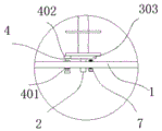
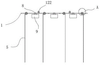
一种用于拦截水中浮游垃圾的拦截器,包括漂浮在水面之上的框架1,在所述框架1的内侧设置有多根支撑轴2,在所述支撑轴2上装配有一可回转的外管3,所述外管3和所述支撑轴2之间配合有轴承,在所述外管3的外壁处设置有多个插孔301,在所述外管3的外壁处设置有多个分隔盘302,相邻分隔盘302之间至少设置一个所述插孔301,所述外管3的一端设置有一从动齿轮303,在所述框架1的外侧插入有一转轴4,所述转轴4和所述框架1之间配合有第一轴承401,所述转轴4插入至框架1内侧的那一端设置有主动齿轮402,所述主动齿轮402与所述齿轮303之间啮合,所述主动齿轮402和从动齿轮303的传动比为N:1,及主动齿轮402旋转N圈,从动齿轮303旋转1圈,通过所述插孔301安插有麻绳5,在所述麻绳5上装配有多个捕获浮游垃圾用的捕获装置6,在所述框架1的外侧旋入有螺丝7,所述螺丝7旋入后抵住所述从动齿轮303,此时所述外管3被固定;在所述框架1的上下侧面处均焊接有纵向的加强杆8,下方的所述加强杆8的底部设置有浮力箱9,所述浮力箱9的上端设置有进出水用的通孔,在通孔内旋入有密封塞10;前后相邻的框架1之间配合有连杆11,连杆11的两端均设置有螺栓12,螺栓12穿过框架1后配合有螺母13;在所述框架1的顶部安装有吊环122。An interceptor for intercepting floating garbage in water, including a
优选地,N=10~20。Preferably, N=10~20.
优选地,所述捕获装置6包括一个插杆601,插杆601的一端设置有倒刺部602,所述插杆601的另一端设置有端头603,在端头603内卡设有橡胶材质的内柱体604,内柱体604的局部延伸至所述端头603的外部,在所述内柱体604内设置有塑料材质的毛刺杆605,所述毛刺杆605远离所述内柱体604的那一端注塑形成一个V字形的钩部606;所述插杆601插入至麻绳5的缝隙处,所述倒刺部602在插入缝隙处后钩住麻绳5;捕获装置6是可灵活的与麻绳5之间进行安装的,安装数量,安装位置,安装间隔等都是可以调整的。无规则的布置,让麻绳在水中可以有效的捕获浮游的垃圾;捕获装置可拆卸,方便更换和维护。Preferably, the
优选地,所述内柱体604的直径向着远离端头603的方向逐渐缩小;内柱体的直径逐渐缩小,使得内柱体604远离端头603的那一端的转动能力增强,使得毛刺杆605可以小幅度的移动,避免伤及附近经过的鱼类,同时动态的毛刺杆605具有更好的垃圾捕捉的效果,可以增加钩住垃圾的几率。Preferably, the diameter of the
优选地,所述毛刺杆605的直径为0.5mm~1.5mm,所述毛刺杆605的长度为10~15cm。Preferably, the diameter of the
优选地,所述转轴4位于框架1外侧的那一端设置有多边形的受力部分441,且所述受力部分441的端面设置有多边形的受力孔442;受力部分441可以借助扳手等工具施加旋转扭矩,受力孔442的设置可以配合手钻等工具进行电动驱动,增加效率。同时采用主动齿轮和从动齿轮的配合,可以减少转动时的负载。Preferably, the end of the
优选地,在所述麻绳5的底部设置有配重装置14。Preferably, a
优选地,所述配重装置14包括一个锥形的配重块141,在所述配重块141的顶部轴心处设置有连接套151,所述麻绳5插入至所述连接套151内,所述连接套151和所述麻绳5之间配合有螺丝161;配重块141的设置是为了方便下方麻绳5,同时也让麻绳5沉入水中,特别适合在有走水情况的河道中;当拆除掉配重块之后,麻绳是可漂浮的,起到动态捕捉的效果。具体的捕获方式可以根据实际需要进行调整,也可以是部分麻绳配备配重装置,部分不配备。Preferably, the
优选地,在所述配重块141的外部设置有安装套171,在所述安装套171内插入有磁钢柱181,所述磁钢柱181凸出至所述安装套171的外部;上述结构的作用是可以组合麻绳,当相邻两根麻绳之间通过磁钢柱181进行吸附时,相邻麻绳前后之间接近平行。当间隔的麻绳之间通过磁钢柱181进行吸附时,麻绳之间交织形成一个网状结构,在水面之下形成更加严密的防护。Preferably, an
以上所述,仅为本发明的具体实施方式,但本发明的保护范围并不局限于此,任何不经过创造性劳动想到的变化或替换,都应涵盖在本发明的保护范围之内。因此,本发明的保护范围应该以权利要求书所限定的保护范围为准。The above are only specific embodiments of the present invention, but the protection scope of the present invention is not limited to this, and any changes or substitutions that are not conceived of without creative work should be included within the protection scope of the present invention. Therefore, the protection scope of the present invention should be based on the protection scope defined by the claims.
Claims (10)
Priority Applications (1)
| Application Number | Priority Date | Filing Date | Title |
|---|---|---|---|
| CN202010626751.XA CN111663506B (en) | 2020-07-02 | 2020-07-02 | An interceptor for intercepting floating garbage in water |
Applications Claiming Priority (1)
| Application Number | Priority Date | Filing Date | Title |
|---|---|---|---|
| CN202010626751.XA CN111663506B (en) | 2020-07-02 | 2020-07-02 | An interceptor for intercepting floating garbage in water |
Publications (2)
| Publication Number | Publication Date |
|---|---|
| CN111663506A true CN111663506A (en) | 2020-09-15 |
| CN111663506B CN111663506B (en) | 2021-08-17 |
Family
ID=72390759
Family Applications (1)
| Application Number | Title | Priority Date | Filing Date |
|---|---|---|---|
| CN202010626751.XA Active CN111663506B (en) | 2020-07-02 | 2020-07-02 | An interceptor for intercepting floating garbage in water |
Country Status (1)
| Country | Link |
|---|---|
| CN (1) | CN111663506B (en) |
Cited By (2)
| Publication number | Priority date | Publication date | Assignee | Title |
|---|---|---|---|---|
| CN112160298A (en) * | 2020-09-24 | 2021-01-01 | 翁典鸿 | Antifouling separation device that environmental protection water treatment used |
| CN112176965A (en) * | 2020-10-12 | 2021-01-05 | 王浩潮 | Ecological environment protection quick detach formula intercepting device |
Citations (4)
| Publication number | Priority date | Publication date | Assignee | Title |
|---|---|---|---|---|
| KR100615966B1 (en) * | 2004-04-29 | 2006-08-28 | 전명춘 | Installation method of antifouling film using hybrid anchor |
| CN208219587U (en) * | 2018-04-12 | 2018-12-11 | 中持水务股份有限公司 | It is a kind of for intercept in hydraulic facility hang floating material clear fishing device |
| CN208604573U (en) * | 2018-08-07 | 2019-03-15 | 南京林业大学 | A kind of Ecological water environment sewage disposal apparatus |
| CN210395282U (en) * | 2019-06-13 | 2020-04-24 | 四川东方水利智能装备工程股份有限公司 | A device for intercepting floating objects on water |
-
2020
- 2020-07-02 CN CN202010626751.XA patent/CN111663506B/en active Active
Patent Citations (4)
| Publication number | Priority date | Publication date | Assignee | Title |
|---|---|---|---|---|
| KR100615966B1 (en) * | 2004-04-29 | 2006-08-28 | 전명춘 | Installation method of antifouling film using hybrid anchor |
| CN208219587U (en) * | 2018-04-12 | 2018-12-11 | 中持水务股份有限公司 | It is a kind of for intercept in hydraulic facility hang floating material clear fishing device |
| CN208604573U (en) * | 2018-08-07 | 2019-03-15 | 南京林业大学 | A kind of Ecological water environment sewage disposal apparatus |
| CN210395282U (en) * | 2019-06-13 | 2020-04-24 | 四川东方水利智能装备工程股份有限公司 | A device for intercepting floating objects on water |
Cited By (2)
| Publication number | Priority date | Publication date | Assignee | Title |
|---|---|---|---|---|
| CN112160298A (en) * | 2020-09-24 | 2021-01-01 | 翁典鸿 | Antifouling separation device that environmental protection water treatment used |
| CN112176965A (en) * | 2020-10-12 | 2021-01-05 | 王浩潮 | Ecological environment protection quick detach formula intercepting device |
Also Published As
| Publication number | Publication date |
|---|---|
| CN111663506B (en) | 2021-08-17 |
Similar Documents
| Publication | Publication Date | Title |
|---|---|---|
| CN204279886U (en) | A kind of sieving garbage contamination removing ship | |
| CN111663506A (en) | An interceptor for intercepting floating garbage in water | |
| CN111616090B (en) | A kind of lifting and rotating marine fish breeding cage and its use method | |
| CN205266649U (en) | Box with a net fish body excrement recovery system | |
| CN110326572A (en) | A kind of wind wave-resisting net casing | |
| CN211080365U (en) | River course sediment removal device for hydraulic engineering | |
| CN211621759U (en) | Rotation type silt collection device of silt clearance system | |
| CN213269817U (en) | Oil borehole operation well-flushing auxiliary device | |
| CN211778052U (en) | A floating submersible pump that prevents deflection | |
| KR101331576B1 (en) | A cleaning apparatus of a well-water basin with brush | |
| CN112779939A (en) | Automatic suction device of circulating water filtering system of nuclear power station | |
| CN110424347A (en) | A kind of river water body activity ponding | |
| CN116641475A (en) | Rural sewage pipeline dredging device and dredging method | |
| CN215253081U (en) | Sediment removal device is used in hydraulic engineering construction | |
| CN205742121U (en) | Oil skimmer | |
| CN210098447U (en) | Automatic scrubbing device of riverbed water intaking pipeline | |
| CN211226573U (en) | Waste water purification device for tunnel construction | |
| CN209468775U (en) | A drainage device for water conservancy and hydropower construction | |
| CN109356227B (en) | Seawater taking device and method | |
| CN214742151U (en) | Suspended long-shaft deep-well pump | |
| CN214657349U (en) | A silt cleaning device for water environment is administered | |
| CN206238134U (en) | A kind of zooplankter collection device | |
| CN215053389U (en) | Reservoir dredging device | |
| CN222989807U (en) | Interception device for sewage treatment of sewage treatment tank | |
| CN220521271U (en) | Shallow water and marsh water purifier |
Legal Events
| Date | Code | Title | Description |
|---|---|---|---|
| PB01 | Publication | ||
| PB01 | Publication | ||
| SE01 | Entry into force of request for substantive examination | ||
| SE01 | Entry into force of request for substantive examination | ||
| TA01 | Transfer of patent application right |
Effective date of registration: 20210729 Address after: 312458 No. 111, Xiaokang Kang door, Hua Tang Village, Jin Ting Town, Shengzhou, Shaoxing, Zhejiang Applicant after: SHENGZHOU WANZHI NETWORK TECHNOLOGY Co.,Ltd. Address before: 518000 909, South China cloth market, No. 20, Baogang Road, Luohu District, Shenzhen, Guangdong Province Applicant before: Zhang Xing |
|
| TA01 | Transfer of patent application right | ||
| GR01 | Patent grant | ||
| GR01 | Patent grant | ||
| EE01 | Entry into force of recordation of patent licensing contract | ||
| EE01 | Entry into force of recordation of patent licensing contract |
Application publication date: 20200915 Assignee: Shengzhou Wanrui Technology Co.,Ltd. Assignor: SHENGZHOU WANZHI NETWORK TECHNOLOGY CO.,LTD. Contract record no.: X2024980031400 Denomination of invention: An interceptor for intercepting floating garbage in water Granted publication date: 20210817 License type: Common License Record date: 20241203 Application publication date: 20200915 Assignee: SHENGZHOU YIYUAN INVESTMENT MANAGEMENT CO.,LTD. Assignor: SHENGZHOU WANZHI NETWORK TECHNOLOGY CO.,LTD. Contract record no.: X2024980031397 Denomination of invention: An interceptor for intercepting floating garbage in water Granted publication date: 20210817 License type: Common License Record date: 20241203 |
|
| EE01 | Entry into force of recordation of patent licensing contract |
Application publication date: 20200915 Assignee: Shengzhou Diligent Metal Materials Co.,Ltd. Assignor: SHENGZHOU WANZHI NETWORK TECHNOLOGY CO.,LTD. Contract record no.: X2024980031918 Denomination of invention: An interceptor for intercepting floating garbage in water Granted publication date: 20210817 License type: Common License Record date: 20241206 |
|
| EE01 | Entry into force of recordation of patent licensing contract | ||
| EE01 | Entry into force of recordation of patent licensing contract |
Application publication date: 20200915 Assignee: Shengzhou Andi Textile Co.,Ltd. Assignor: SHENGZHOU WANZHI NETWORK TECHNOLOGY CO.,LTD. Contract record no.: X2024980035405 Denomination of invention: An interceptor for intercepting floating garbage in water Granted publication date: 20210817 License type: Common License Record date: 20241217 Application publication date: 20200915 Assignee: Shengzhou Yonggu Commercial Concrete Co.,Ltd. Assignor: SHENGZHOU WANZHI NETWORK TECHNOLOGY CO.,LTD. Contract record no.: X2024980035404 Denomination of invention: An interceptor for intercepting floating garbage in water Granted publication date: 20210817 License type: Common License Record date: 20241217 Application publication date: 20200915 Assignee: ZHEJIANG GAOJING METALFORMING MACHINE CO.,LTD. Assignor: SHENGZHOU WANZHI NETWORK TECHNOLOGY CO.,LTD. Contract record no.: X2024980035406 Denomination of invention: An interceptor for intercepting floating garbage in water Granted publication date: 20210817 License type: Common License Record date: 20241217 |
|
| EE01 | Entry into force of recordation of patent licensing contract | ||
| EC01 | Cancellation of recordation of patent licensing contract |
Assignee: SHENGZHOU YIYUAN INVESTMENT MANAGEMENT CO.,LTD. Assignor: SHENGZHOU WANZHI NETWORK TECHNOLOGY CO.,LTD. Contract record no.: X2024980031397 Date of cancellation: 20251211 Assignee: Shengzhou Wanrui Technology Co.,Ltd. Assignor: SHENGZHOU WANZHI NETWORK TECHNOLOGY CO.,LTD. Contract record no.: X2024980031400 Date of cancellation: 20251211 Assignee: Shengzhou Yonggu Commercial Concrete Co.,Ltd. Assignor: SHENGZHOU WANZHI NETWORK TECHNOLOGY CO.,LTD. Contract record no.: X2024980035404 Date of cancellation: 20251211 Assignee: Shengzhou Andi Textile Co.,Ltd. Assignor: SHENGZHOU WANZHI NETWORK TECHNOLOGY CO.,LTD. Contract record no.: X2024980035405 Date of cancellation: 20251211 Assignee: ZHEJIANG GAOJING METALFORMING MACHINE CO.,LTD. Assignor: SHENGZHOU WANZHI NETWORK TECHNOLOGY CO.,LTD. Contract record no.: X2024980035406 Date of cancellation: 20251211 |
|
| EC01 | Cancellation of recordation of patent licensing contract | ||
| EC01 | Cancellation of recordation of patent licensing contract |
Assignee: Shengzhou Diligent Metal Materials Co.,Ltd. Assignor: SHENGZHOU WANZHI NETWORK TECHNOLOGY CO.,LTD. Contract record no.: X2024980031918 Date of cancellation: 20251212 |
|
| EC01 | Cancellation of recordation of patent licensing contract |