CN111663251A - Full-automatic mattress surface cloth edge locking machine and mattress surface cloth edge locking method - Google Patents
Full-automatic mattress surface cloth edge locking machine and mattress surface cloth edge locking method Download PDFInfo
- Publication number
- CN111663251A CN111663251A CN202010663093.1A CN202010663093A CN111663251A CN 111663251 A CN111663251 A CN 111663251A CN 202010663093 A CN202010663093 A CN 202010663093A CN 111663251 A CN111663251 A CN 111663251A
- Authority
- CN
- China
- Prior art keywords
- manipulator
- mattress
- assembly
- edge locking
- pressing plate
- Prior art date
- Legal status (The legal status is an assumption and is not a legal conclusion. Google has not performed a legal analysis and makes no representation as to the accuracy of the status listed.)
- Pending
Links
Images


Classifications
-
- D—TEXTILES; PAPER
- D05—SEWING; EMBROIDERING; TUFTING
- D05B—SEWING
- D05B1/00—General types of sewing apparatus or machines without mechanism for lateral movement of the needle or the work or both
- D05B1/08—General types of sewing apparatus or machines without mechanism for lateral movement of the needle or the work or both for making multi-thread seams
- D05B1/18—Seams for protecting or securing edges
-
- D—TEXTILES; PAPER
- D05—SEWING; EMBROIDERING; TUFTING
- D05B—SEWING
- D05B27/00—Work-feeding means
-
- D—TEXTILES; PAPER
- D05—SEWING; EMBROIDERING; TUFTING
- D05B—SEWING
- D05B29/00—Pressers; Presser feet
-
- D—TEXTILES; PAPER
- D05—SEWING; EMBROIDERING; TUFTING
- D05B—SEWING
- D05B35/00—Work-feeding or -handling elements not otherwise provided for
Landscapes
- Engineering & Computer Science (AREA)
- Textile Engineering (AREA)
- Sewing Machines And Sewing (AREA)
Abstract
本发明公开了一种全自动的床垫面布锁边机及床垫面布锁边方法,全自动的床垫面布锁边机包括机身、工作台组件、锁边组件、压紧组件和机械手组件,工作台组件包括旋转机构和旋转工作台;锁边组件包括平移机构、摆角机构和锁边机构;压紧组件包括压板传动机构和压板;机械手组件包括机械手传动机构和机械手。本发明的有益效果是:本发明的全自动的床垫面布锁边机能够全自动地进行床垫面布加工,自动加工时,能够加工床垫面布的圆角,能够进行锁边,且能对厚床垫面布进行加工,其加工效果优于人工加工。

The present invention discloses a fully automatic mattress cover fabric edge locking machine and a mattress cover fabric edge locking method. The fully automatic mattress cover fabric edge locking machine comprises a machine body, a workbench assembly, an edge locking assembly, a pressing assembly and a manipulator assembly. The workbench assembly comprises a rotating mechanism and a rotating workbench; the edge locking assembly comprises a translation mechanism, an angle swinging mechanism and an edge locking mechanism; the pressing assembly comprises a pressing plate transmission mechanism and a pressing plate; the manipulator assembly comprises a manipulator transmission mechanism and a manipulator. The beneficial effects of the present invention are as follows: the fully automatic mattress cover fabric edge locking machine of the present invention can fully automatically process the mattress cover fabric. During automatic processing, it can process the rounded corners of the mattress cover fabric, can perform edge locking, and can process thick mattress cover fabrics. Its processing effect is better than manual processing.
Description
技术领域technical field
本发明涉及机械加工技术领域,特别是一种全自动的床垫面布锁边机及床垫面布锁边方法。The invention relates to the technical field of mechanical processing, in particular to an automatic mattress surface cloth sewing machine and a mattress surface fabric sewing method.
背景技术Background technique
现有的床垫面布锁边生产工序,一般有工人手工操作一台工业锁边机进行床垫面布锁边作业,工人操作工业锁边机作业存在很大的人为因素,其生产出来的产品质量参差不齐,生产效率偏低,在生产和质检上都需要占用很大的人力物力。随着机械自动化生产的发展与进步,机械自动化生产取代人工作业,能够降低人力成本并提高生产效率。市场上现有一种由三台多针缝纫机头组成的自动床垫面布缝边机,这种自动床垫面布缝边机不能加工床垫面布的圆角边,不能自动锁边、只能缝两根直线;不能加工厚料,加工效果不急手工加工的好。In the existing production process of overlocking mattress cover fabrics, generally a worker manually operates an industrial overlocking machine to perform overlocking operation of mattress fabrics. The product quality is uneven and the production efficiency is low, which requires a lot of manpower and material resources in production and quality inspection. With the development and progress of mechanical automation production, mechanical automation production replaces manual work, which can reduce labor costs and improve production efficiency. There is an automatic mattress cover sewing machine consisting of three multi-needle sewing machine heads on the market. It can sew two straight lines; it cannot process thick materials, and the processing effect is not urgent, and it is good for manual processing.
发明内容SUMMARY OF THE INVENTION
本发明要解决的技术问题是针对上述现有技术的不足,提供了一种全自动的床垫面布锁边机及床垫面布锁边方法。The technical problem to be solved by the present invention is to provide a fully automatic mattress top cloth overlocking machine and a mattress top fabric overlock method in view of the deficiencies of the above-mentioned prior art.
为解决上述技术问题,本发明所采取的技术方案是:一种全自动的床垫面布锁边机,包括机身、工作台组件、锁边组件、压紧组件和机械手组件,工作台组件包括旋转机构和旋转工作台,旋转机构安装在机身上,旋转工作台与旋转机构连接,旋转工作台置于机身上端且平行于机身上表面;锁边组件包括平移机构、摆角机构和锁边机构,平移机构安装在机身侧边,摆角机构安装在平移机构,摆角机构上端安装有锁边机构;机身设有压板安装支架和机械手安装支架,压板安装支架和机械手安装支架在机身侧边向上延伸至旋转工作台之上;压紧组件包括压板传动机构和压板,压板传动机构与压板安装支架的上端位置连接,压板传动机构连接并驱动压板上下移动,压板正对旋转工作台;机械手组件包括机械手传动机构和机械手,机械手传动机构与机械手安装支架的上端位置连接,机械手传动机构连接并驱动机械手上下移动和左右移动,机械手位于锁边机构朝向机身方向的前端。In order to solve the above-mentioned technical problems, the technical scheme adopted by the present invention is: a fully automatic mattress surface cloth sewing machine, including a body, a workbench assembly, a seaming assembly, a pressing assembly and a manipulator assembly, a workbench assembly It includes a rotating mechanism and a rotating worktable. The rotating mechanism is installed on the fuselage. The rotating worktable is connected to the rotating mechanism. The rotating worktable is placed on the upper end of the fuselage and is parallel to the upper surface of the fuselage. The edge locking assembly includes a translation mechanism and a swing angle mechanism. and locking mechanism, the translation mechanism is installed on the side of the fuselage, the swing angle mechanism is installed on the translation mechanism, and the locking mechanism is installed on the upper end of the swing angle mechanism; The bracket extends upward on the side of the fuselage to the rotary table; the pressing assembly includes a pressure plate transmission mechanism and a pressure plate, the pressure plate transmission mechanism is connected with the upper end position of the pressure plate installation bracket, and the pressure plate transmission mechanism is connected and drives the pressure plate to move up and down, the pressure plate is facing Rotary table; the manipulator assembly includes a manipulator transmission mechanism and a manipulator, the manipulator transmission mechanism is connected with the upper end position of the manipulator mounting bracket, the manipulator transmission mechanism is connected and drives the manipulator to move up and down and left and right, and the manipulator is located at the front end of the edge locking mechanism toward the fuselage.
上述技术方案中,旋转机构包括工作台传动总成、第一驱动电机和第一皮带轮组,工作台传动总成和第一驱动电机安装在机身上,工作台传动总成与第一驱动电机之间通过第一皮带轮组连接传动,旋转工作台连接在工作台传动总成的上端。In the above technical solution, the rotating mechanism includes a worktable transmission assembly, a first drive motor and a first pulley set, the worktable transmission assembly and the first drive motor are installed on the fuselage, and the worktable transmission assembly and the first drive motor The transmission is connected through the first pulley group, and the rotary table is connected to the upper end of the table transmission assembly.
上述技术方案中,平移机构包括第二驱动电机、第二皮带轮组、第一直线导轨、第一滑台,摆角机构包括第三驱动电机和摆角传动总成;第一直线导轨水平安装在机身侧边,第一滑台安装在第一直线导轨上且可沿第一直线导轨水平移动,第二驱动电机与第一滑台之间通过第二皮带轮组连接传动,第三驱动电机安装在第一滑台上,第三驱动电机的上端连接摆角传动总成,摆角传动总成的上端连接锁边机构。In the above technical solution, the translation mechanism includes a second drive motor, a second pulley group, a first linear guide rail, and a first sliding table, and the swing angle mechanism includes a third drive motor and a swing angle transmission assembly; the first linear guide rail is horizontal Installed on the side of the fuselage, the first sliding table is installed on the first linear guide rail and can move horizontally along the first linear guide rail. The three driving motors are installed on the first sliding table, the upper end of the third driving motor is connected to the swing angle transmission assembly, and the upper end of the swing angle transmission assembly is connected to the locking mechanism.
上述技术方案中,机械手传动机构包括第四驱动电机、第三皮带轮组、第二直线导轨、第二滑台、驱动气缸、第三直线导轨、第三滑台;第二直线导轨水平安装在机械手安装支架的上端位置,第二滑台安装在第二直线导轨上,第四驱动电机与第二滑台通过第三皮带轮组连接传动,驱动气缸和第三直线导轨纵向竖直安装在第二滑台上,第三滑台安装在第三直线导轨上;驱动气缸连接并驱动第三滑台沿第三直线导轨的轨道移动;第三滑台上紧固安装机械手。In the above technical solution, the manipulator transmission mechanism includes a fourth drive motor, a third pulley group, a second linear guide, a second slide, a drive cylinder, a third linear guide, and a third slide; the second linear guide is horizontally installed on the manipulator. The upper end position of the installation bracket, the second sliding table is installed on the second linear guide rail, the fourth drive motor and the second sliding table are connected and driven through the third pulley group, and the driving cylinder and the third linear guide rail are vertically installed on the second sliding table. On the table, the third sliding table is installed on the third linear guide rail; the driving cylinder is connected and drives the third sliding table to move along the track of the third linear guide rail; the manipulator is fastened on the third sliding table.
上述技术方案中,压板与压板传动机构之间为可旋转连接。In the above technical solution, the pressing plate and the pressing plate transmission mechanism are rotatably connected.
上述技术方案中,工作台传动总成的轴心与压板传动机构的轴心重合。In the above technical solution, the axis of the worktable transmission assembly coincides with the axis of the platen transmission mechanism.
一种床垫面布锁边方法,采用以上技术方案中的全自动床垫面布锁边机,其锁边步骤为,A method for overlocking a mattress surface fabric, using the automatic mattress fabric overlocking machine in the above technical solution, and the edge locking steps are as follows:
(1)床垫面布放置至旋转工作台,床垫面布的中心位于旋转工作台及压板中心,压板向下移动将床垫面布压紧固定;(1) Place the mattress cover on the rotating table, the center of the mattress cover is located at the center of the rotating table and the pressure plate, and the pressure plate moves down to compress and fix the mattress cover;
(2)摆角机构驱动锁边机构顺时针旋转45°,平移机构带动锁边机构进入床垫面布的第一个针孔位置;(2) The swing angle mechanism drives the side lock mechanism to rotate 45° clockwise, and the translation mechanism drives the side lock mechanism to enter the first pinhole position of the mattress cloth;
(3)机械手在机械手传动机构驱动下按压床垫面布,使床垫面布不能转动,锁边机构逆时针旋转45°;(3) The manipulator presses the mattress cloth under the drive of the manipulator transmission mechanism, so that the mattress cloth cannot be rotated, and the locking mechanism rotates 45° counterclockwise;
(4)旋转机构驱动旋转工作台旋转,锁边机构对床垫面布进行锁边缝合,摆角机构和平移机构根据床垫面布的旋转位置对锁边机构的旋转角度及平移位置进行调整;旋转机构旋转360°,锁边机构完成床垫面布6周边的锁边缝合;(4) The rotating mechanism drives the rotary table to rotate, the overlocking mechanism stitches the mattress cloth, and the swing angle mechanism and the translation mechanism adjust the rotation angle and translation position of the overlocking mechanism according to the rotation position of the mattress cloth. ; The rotating mechanism rotates 360°, and the overlock mechanism completes the overlock stitching around the
(5)平移机构带动锁边机构退回到初始位置。(5) The translation mechanism drives the side locking mechanism to return to the initial position.
上述方法的步骤(2)中,锁边机构进入的第一个针孔位置位于床垫面布一直边的中间位置。In step (2) of the above method, the position of the first pinhole entered by the hemming mechanism is located in the middle of the straight edge of the mattress cover.
上述方法的步骤(4)中,锁边机构在对床垫面布的直边进行锁边时,锁边机构前端的朝向始终与床垫面布的直边保持垂直,锁边机构在对床垫面布的圆角锁边时,锁边机构前端始终朝向该圆角弧边对应的圆心位置。In step (4) of the above method, when the edge-locking mechanism locks the straight edge of the mattress cover, the direction of the front end of the edge-locking mechanism is always vertical to the straight edge of the mattress cover. When the rounded corner of the cushion cloth is locked, the front end of the locking mechanism always faces the center of the circle corresponding to the rounded arc edge.
本发明的有益效果是:本发明的全自动的床垫面布锁边机能够全自动地进行床垫面布加工,自动加工时,能够加工床垫面布的圆角,能够进行锁边,且能对厚床垫面布进行加工,其加工效果优于人工加工。The beneficial effects of the present invention are as follows: the fully automatic mattress top cloth sewing machine of the present invention can automatically process the mattress top cloth, and during automatic processing, it can process the rounded corners of the mattress top cloth, and can perform hemming, And it can process thick mattress surface cloth, and its processing effect is better than manual processing.
附图说明Description of drawings
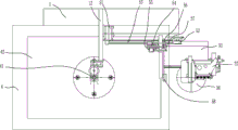
图1是本发明的整体结构前视示意图。FIG. 1 is a schematic front view of the overall structure of the present invention.
图2是本发明的整体结构俯视示意图。FIG. 2 is a schematic top view of the overall structure of the present invention.
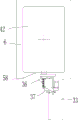
图3是本发明的工作状态一的示意图。FIG. 3 is a schematic diagram of working state 1 of the present invention.
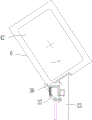
图4是本发明的工作状态二的示意图。FIG. 4 is a schematic diagram of the second working state of the present invention.
图5是本发明的工作状态三的示意图。FIG. 5 is a schematic diagram of the third working state of the present invention.
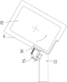
图6是本发明的工作状态四的示意图。FIG. 6 is a schematic diagram of the fourth working state of the present invention.
图7是本发明的工作状态五的示意图。FIG. 7 is a schematic diagram of the fifth working state of the present invention.
图8是本发明的工作状态六的示意图。FIG. 8 is a schematic diagram of the sixth working state of the present invention.
图9是本发明的工作状态七的示意图。FIG. 9 is a schematic diagram of the seventh working state of the present invention.
图10是本发明的工作状态八的示意图。FIG. 10 is a schematic diagram of the eighth working state of the present invention.
图11是本发明的工作状态九的示意图。FIG. 11 is a schematic diagram of working state nine of the present invention.
附图标记reference number
1、机身;11、压板安装支架;12、机械手安装支架;2、工作台组件;21、工作台传动总成;22、第一驱动电机;23、第一皮带轮组;24、旋转工作台;3、锁边组件;31、第二驱动电机;32、第二皮带轮组;33、第一直线导轨;34、第一滑台;35、第三驱动电机;36、摆角传动总成;37、锁边机构;4、压紧组件;41、压板传动机构;42、压板;5、机械手组件;51、第四驱动电机;52、第三皮带轮组;53、第二直线导轨;54、第二滑台;55、驱动气缸;56、第三直线导轨;57、第三滑台;58、机械手;6、床垫面布。1. Body; 11. Platen mounting bracket; 12. Manipulator mounting bracket; 2. Worktable assembly; 21. Worktable transmission assembly; 22. First drive motor; 23. First pulley set; 3. Overlock assembly; 31. Second drive motor; 32, Second pulley set; 33, First linear guide rail; 34, First slide table; ; 37, locking mechanism; 4, pressing assembly; 41, pressure plate transmission mechanism; 42, pressure plate; 5, manipulator assembly; 51, fourth drive motor; 52, third pulley group; 53, second linear guide rail; 54 5. The second sliding table; 55, the driving cylinder; 56, the third linear guide rail; 57, the third sliding table; 58, the manipulator; 6, the mattress surface cloth.
具体实施方式Detailed ways
下面结合附图对本发明作进一步详细的说明。The present invention will be described in further detail below in conjunction with the accompanying drawings.
如图1-2所示,为一种全自动的床垫面布6锁边机,其主要包括机身1、工作台组件2、锁边组件3、压紧组件4和机械手组件5。机身1作为全自动的床垫面布6锁边机的安装主体,用于工作台组件2、锁边组件3、压紧组件4以及机械手组件5的紧固安装。As shown in Figure 1-2, it is a fully automatic
工作台组件2主要用于放置和旋转所要进行锁边的床垫面布6,工作台组件2包括有旋转机构和旋转工作台24,旋转机构包括工作台传动总成21、第一驱动电机22、第一皮带轮组23件,工作台传动总成21和第一驱动电机22紧固安装在机身1的上表面,工作台传动总成21的轴心垂直于机身1上表面,工作台传动总成21与第一驱动电机22之间通过第一皮带轮实现连接传动,旋转工作台24连接在工作台传动总成21的上端, 旋转工作台24平行于机身1的上表面。使用时,床垫面布6放置在旋转工作台24上,通过第一驱动电机22提供旋转动力,经第一皮带轮组23件和工作台传动总成21传递使旋转工作台24旋转。在实际应用时,工作台组件2不限于使用工作台传动总成21、第一驱动电机22以及第一皮带轮组23件作为旋转机构,以实现旋转工作台24的安装和旋转功能,其他能够实现相同功能的旋转机构也可替代使用。The
锁边组件3主要用于对床垫面布6的边缘进行锁边缝合,锁边组件3包括有平移机构、摆角机构和锁边机构37,平移机构包括第二驱动电机31、第二皮带轮组32、第一直线导轨33和第一滑台34,摆角机构包括第三驱动电机35和摆角传动总成36。第一直线导轨33水平安装在机身1的右端,第一直线导轨33的轨道方向为左右移动方向,即水平靠近或远离床垫面布6的方向,第一直线导轨33的轨道上安装有第一滑台34,第一滑台34可沿第一直线导轨33的轨道方向移动,第一滑台34与第二驱动电机31之间通过第二皮带轮组32连接传动,第二驱动电机31作为第一滑台34在第一直线轨道移动的动力源。在第一滑台34上固定安装有第三驱动电机35,第三驱动电机35的上端连接摆角传动总成36,摆角传动总成36的轴心垂直于机身1的上表面,摆角传动总成36的上端连接锁边机构37。锁边机构37通过摆角机构实现沿摆角传动总成36轴心的旋转运动,第三驱动电机35可进行正向转动和反向转动以驱动锁边机构37正向转动和反向转动。锁边机构37通过平移机构实现自身在水平方向靠近或远离床垫面布6的移动。在实际应用时,锁边组件3不限于使用第二驱动电机31、第二皮带轮组32、第一直线导轨33和第一滑台34作为平移机构实现锁边机构37在水平方向的移动,锁边组件3也不限于使用第三驱动电机35和摆角传动总成36作为摆角机构实现锁边机构37的纵向旋转移动,其他能够实现相同功能的摆角机构也可替代使用。The
压紧组件4主要用于防止床垫面布6进行锁边时移动,造成锁边偏移甚至床垫面布6脱离。压紧组件4包括压板传动机构41和压板42,机身1的侧边设有一压板安装支架11,压板安装支架11在机身1的侧边向上延伸至旋转工作台24之上,压板传动机构41紧固安装在压板安装支架11上,并且压板传动机构41位于旋转工作台24的正上方,压板传动机构41的下端连接安装有压板42,压板42与旋转工作台24相互平行,压板传动机构41可驱动压板42上下移动,压板42向下移动可与旋转工作台24一同压紧床垫面布6,防止床垫面布6在水平方向、竖直方向的平移运动。压板42与压板传动机构41之间为可旋转连接,在旋转工作台24带动床垫面布6旋转时,压板42可跟随床垫面布6一同旋转。为保障旋转工作台24与压板42对床垫面板的作用力平衡,压板传动机构41的轴心与工作台传动总成21的轴心重合。The pressing component 4 is mainly used to prevent the
机械手组件5主要用于在锁边机构37第一次进入床垫面布6需要回转时按压住床垫面布6。机械手组件5安装在机身1及旋转工作台24的上方,机械手组件5包括有机械手58和用于驱动机械手58上下左右移动的机械手传动机构,机械手传动机构包括第四驱动电机51、第三皮带轮组52、第二直线导轨53、第二滑台54、驱动气缸55、第三直线导轨56、第三滑台57。机身1的侧边设有一机械手安装支架12,机械手安装支架12在机身1的侧边向上延伸至旋转工作台24之上,第二直线导轨53紧固安装在机械手安装支架12的上端位置,第二直线导轨53的轨道水平设置,第二滑台54安装在第二直线导轨53上,第四驱动电机51安装在第二直线导轨53的侧端,第四驱动电机51与第二滑台54通过第三皮带轮组52连接传动;驱动气缸55和第三直线导轨56安装在第二滑台54上,第三直线导轨56的轨道纵向竖直设置,第三滑台57安装在第三直线导轨56上,驱动气缸55连接并驱动第三滑台57沿第三直线导轨56的轨道移动;第三滑台57上紧固安装机械手58,机械手58位于锁边机构37朝向机身1方向的前端。根据不同床垫面布6的尺寸要求,机械手58的按压床垫面布6的位置通过机械手传动机构进行上下左右移动调整。在实际应用时,机械手传动机构不限于使用第四驱动电机51、第三皮带轮组52、第二直线导轨53、第二滑台54、驱动气缸55、第三直线导轨56以及第三滑台57实现机械手58上下左右移动,其他能够实现相同功能的机械手传动机构也可替代使用。The
全自动的床垫面布6锁边机在使用时,将床垫面布6放置在旋转工作台24上,床垫面布6的中心位于工作台传动总成21及压板传动机构41的轴心位置,压板42将床垫面布6压紧在旋转工作台24上,锁边机构37移动至床垫面布6边缘,旋转工作台24一边旋转,锁边机构37一边进行锁边缝合,锁边机构37通过平移机构和摆角机构调整与床垫布面的距离和角度。When the fully automatic mattress
结合图3-11所示,全自动的床垫面布6锁边机的锁边方法,具体如下:Combined with Fig. 3-11, the overlocking method of the automatic mattress
(1)床垫面布6放置至旋转工作台24,床垫面布6的中心位于旋转工作台24及压板42中心位置,压板42向下移动将床垫面布6压紧固定(图3);(1) The
(2)摆角机构驱动锁边机构37顺时针旋转45°,平移机构带动锁边机构37沿第一直线导轨33移动并进入床垫面布6的第一个针孔位置(图4-5);(2) The swing angle mechanism drives the side-locking
(3)机械手58在机械手传动机构驱动下按压床垫面布6,使床垫面布6不能转动,锁边机构37逆时针旋转45°(图6);(3) The
(4)旋转机构驱动旋转工作台24旋转,锁边机构37对床垫面布6进行锁边缝合,摆角机构和平移机构根据床垫面布6的旋转位置对锁边机构37的旋转角度及平移位置进行调整;旋转机构旋转360°,锁边机构37完成床垫面布6周边的锁边缝合(图7-10);(4) The rotating mechanism drives the rotating table 24 to rotate, the
(5)平移机构带动锁边机构37沿第一直线导轨33移动并退回到初始位置(图11)。(5) The translation mechanism drives the
其中,上述锁边方法的步骤(2)中,锁边机构37进入的第一个针孔位置位于床垫面布6一直边的中间位置。Wherein, in step (2) of the above-mentioned hemming method, the position of the first pinhole entered by the
其中,上述锁边方法的步骤(4)中,锁边机构37在对床垫面布6的直边进行锁边时,锁边机构37的机头朝向始终与床垫面布6的直边保持垂直,锁边机构37在对床垫面布6的圆角锁边时,锁边机构37的机头始终朝向该圆角弧边对应的圆心位置。Wherein, in step (4) of the above-mentioned hemming method, when the
上述锁边方法以长方体结构的床垫面布6为例进行锁边操作说明,其锁边方式同样适用于圆柱形等其他形状的床垫面布6的锁边缝合。The above-mentioned seaming method takes the
以上的实施例只是在于说明而不是限制本发明,故凡依本发明专利申请范围所述的方法所做的等效变化或修饰,均包括于本发明专利申请范围内。The above embodiments are only intended to illustrate rather than limit the present invention, so all equivalent changes or modifications made according to the methods described in the scope of the patent application of the present invention are included in the scope of the patent application of the present invention.
Claims (9)
Priority Applications (1)
| Application Number | Priority Date | Filing Date | Title |
|---|---|---|---|
| CN202010663093.1A CN111663251A (en) | 2020-07-10 | 2020-07-10 | Full-automatic mattress surface cloth edge locking machine and mattress surface cloth edge locking method |
Applications Claiming Priority (1)
| Application Number | Priority Date | Filing Date | Title |
|---|---|---|---|
| CN202010663093.1A CN111663251A (en) | 2020-07-10 | 2020-07-10 | Full-automatic mattress surface cloth edge locking machine and mattress surface cloth edge locking method |
Publications (1)
| Publication Number | Publication Date |
|---|---|
| CN111663251A true CN111663251A (en) | 2020-09-15 |
Family
ID=72392263
Family Applications (1)
| Application Number | Title | Priority Date | Filing Date |
|---|---|---|---|
| CN202010663093.1A Pending CN111663251A (en) | 2020-07-10 | 2020-07-10 | Full-automatic mattress surface cloth edge locking machine and mattress surface cloth edge locking method |
Country Status (1)
| Country | Link |
|---|---|
| CN (1) | CN111663251A (en) |
Citations (6)
| Publication number | Priority date | Publication date | Assignee | Title |
|---|---|---|---|---|
| GB741816A (en) * | 1952-07-15 | 1955-12-14 | Thomas Frederick Summerton | Improvements in or relating to the production of mattresses and the like |
| CN2205837Y (en) * | 1994-08-04 | 1995-08-23 | 宁波梦神床垫机械有限公司 | Mattress seam-closing machine with rotary working table |
| EP0682135A1 (en) * | 1994-05-12 | 1995-11-15 | Resta S.R.L. | Device for rotating a mattress on the working table of a hemming machine |
| US5515796A (en) * | 1994-03-11 | 1996-05-14 | L&P Property Management Company | Mattress sewing and handling apparatus |
| CN110387641A (en) * | 2019-07-12 | 2019-10-29 | 佛山市科华智缝设备有限公司 | Automatic overlocking machine |
| CN212451872U (en) * | 2020-07-10 | 2021-02-02 | 东莞新永腾自动化设备有限公司 | A fully automatic mattress surface cloth sewing machine |
-
2020
- 2020-07-10 CN CN202010663093.1A patent/CN111663251A/en active Pending
Patent Citations (6)
| Publication number | Priority date | Publication date | Assignee | Title |
|---|---|---|---|---|
| GB741816A (en) * | 1952-07-15 | 1955-12-14 | Thomas Frederick Summerton | Improvements in or relating to the production of mattresses and the like |
| US5515796A (en) * | 1994-03-11 | 1996-05-14 | L&P Property Management Company | Mattress sewing and handling apparatus |
| EP0682135A1 (en) * | 1994-05-12 | 1995-11-15 | Resta S.R.L. | Device for rotating a mattress on the working table of a hemming machine |
| CN2205837Y (en) * | 1994-08-04 | 1995-08-23 | 宁波梦神床垫机械有限公司 | Mattress seam-closing machine with rotary working table |
| CN110387641A (en) * | 2019-07-12 | 2019-10-29 | 佛山市科华智缝设备有限公司 | Automatic overlocking machine |
| CN212451872U (en) * | 2020-07-10 | 2021-02-02 | 东莞新永腾自动化设备有限公司 | A fully automatic mattress surface cloth sewing machine |
Similar Documents
| Publication | Publication Date | Title |
|---|---|---|
| CN212451872U (en) | A fully automatic mattress surface cloth sewing machine | |
| CN208762675U (en) | Overseam machine control system and overedger | |
| CN111663251A (en) | Full-automatic mattress surface cloth edge locking machine and mattress surface cloth edge locking method | |
| CN108823822B (en) | Three-dimensional rotary feeding sewing machine | |
| CN217077984U (en) | Cloth piece serging sewing machine | |
| CN215209931U (en) | Cloth clamping device of computer flat car sewing machine | |
| CN111254593A (en) | Automatic sewing machine capable of rotating to sew | |
| CN222160588U (en) | Interchangeable cam sewing presser device and sewing equipment | |
| CN110485063B (en) | Diversified peripheral sewing press-fit equipment | |
| CN208649622U (en) | A kind of two type cantilever form machines | |
| CN218026648U (en) | Curved sewing machine is used in leather gloves production | |
| CN215517921U (en) | Hemming and sewing mechanism used on sewing equipment | |
| CN114960041A (en) | Full-automatic double-needle chain type machine head sewing machine capable of rotating randomly | |
| CN212451871U (en) | Material taking device for serging machine | |
| CN210085769U (en) | Full-automatic double-needle head sewing machine capable of rotating randomly | |
| CN210368186U (en) | Full-automatic super thick material jujube beater | |
| CN210796862U (en) | Garment sewing fork machine | |
| CN108277582A (en) | A kind of template machine | |
| CN211036329U (en) | Fabric serging mechanism | |
| CN103194866A (en) | Synchronous rotating mechanism for shuttle race | |
| CN111850863A (en) | Fully automatic double needle head sewing machine that can be rotated freely | |
| CN215906367U (en) | Air suction type full-automatic production line template machine | |
| CN119287593B (en) | Sealing sewing machine | |
| CN222908258U (en) | Edge sealing device for cushion processing | |
| CN221701794U (en) | Sewing device with material alignment structure |
Legal Events
| Date | Code | Title | Description |
|---|---|---|---|
| PB01 | Publication | ||
| PB01 | Publication | ||
| SE01 | Entry into force of request for substantive examination | ||
| SE01 | Entry into force of request for substantive examination | ||
| WD01 | Invention patent application deemed withdrawn after publication |
Application publication date: 20200915 |
|
| WD01 | Invention patent application deemed withdrawn after publication |