CN111649495B - Folding solar heat collector - Google Patents
Folding solar heat collector Download PDFInfo
- Publication number
- CN111649495B CN111649495B CN202010539637.3A CN202010539637A CN111649495B CN 111649495 B CN111649495 B CN 111649495B CN 202010539637 A CN202010539637 A CN 202010539637A CN 111649495 B CN111649495 B CN 111649495B
- Authority
- CN
- China
- Prior art keywords
- frame
- hinged
- connecting rod
- threaded sleeve
- fixed frame
- Prior art date
- Legal status (The legal status is an assumption and is not a legal conclusion. Google has not performed a legal analysis and makes no representation as to the accuracy of the status listed.)
- Active
Links
Images


Classifications
-
- F—MECHANICAL ENGINEERING; LIGHTING; HEATING; WEAPONS; BLASTING
- F24—HEATING; RANGES; VENTILATING
- F24S—SOLAR HEAT COLLECTORS; SOLAR HEAT SYSTEMS
- F24S10/00—Solar heat collectors using working fluids
- F24S10/70—Solar heat collectors using working fluids the working fluids being conveyed through tubular absorbing conduits
- F24S10/72—Solar heat collectors using working fluids the working fluids being conveyed through tubular absorbing conduits the tubular conduits being integrated in a block; the tubular conduits touching each other
-
- F—MECHANICAL ENGINEERING; LIGHTING; HEATING; WEAPONS; BLASTING
- F24—HEATING; RANGES; VENTILATING
- F24S—SOLAR HEAT COLLECTORS; SOLAR HEAT SYSTEMS
- F24S25/00—Arrangement of stationary mountings or supports for solar heat collector modules
-
- F—MECHANICAL ENGINEERING; LIGHTING; HEATING; WEAPONS; BLASTING
- F24—HEATING; RANGES; VENTILATING
- F24S—SOLAR HEAT COLLECTORS; SOLAR HEAT SYSTEMS
- F24S30/00—Arrangements for moving or orienting solar heat collector modules
-
- F—MECHANICAL ENGINEERING; LIGHTING; HEATING; WEAPONS; BLASTING
- F24—HEATING; RANGES; VENTILATING
- F24S—SOLAR HEAT COLLECTORS; SOLAR HEAT SYSTEMS
- F24S40/00—Safety or protection arrangements of solar heat collectors; Preventing malfunction of solar heat collectors
- F24S40/20—Cleaning; Removing snow
-
- F—MECHANICAL ENGINEERING; LIGHTING; HEATING; WEAPONS; BLASTING
- F24—HEATING; RANGES; VENTILATING
- F24S—SOLAR HEAT COLLECTORS; SOLAR HEAT SYSTEMS
- F24S25/00—Arrangement of stationary mountings or supports for solar heat collector modules
- F24S2025/01—Special support components; Methods of use
- F24S2025/012—Foldable support elements
-
- F—MECHANICAL ENGINEERING; LIGHTING; HEATING; WEAPONS; BLASTING
- F24—HEATING; RANGES; VENTILATING
- F24S—SOLAR HEAT COLLECTORS; SOLAR HEAT SYSTEMS
- F24S30/00—Arrangements for moving or orienting solar heat collector modules
- F24S2030/10—Special components
- F24S2030/11—Driving means
-
- Y—GENERAL TAGGING OF NEW TECHNOLOGICAL DEVELOPMENTS; GENERAL TAGGING OF CROSS-SECTIONAL TECHNOLOGIES SPANNING OVER SEVERAL SECTIONS OF THE IPC; TECHNICAL SUBJECTS COVERED BY FORMER USPC CROSS-REFERENCE ART COLLECTIONS [XRACs] AND DIGESTS
- Y02—TECHNOLOGIES OR APPLICATIONS FOR MITIGATION OR ADAPTATION AGAINST CLIMATE CHANGE
- Y02E—REDUCTION OF GREENHOUSE GAS [GHG] EMISSIONS, RELATED TO ENERGY GENERATION, TRANSMISSION OR DISTRIBUTION
- Y02E10/00—Energy generation through renewable energy sources
- Y02E10/40—Solar thermal energy, e.g. solar towers
- Y02E10/44—Heat exchange systems
-
- Y—GENERAL TAGGING OF NEW TECHNOLOGICAL DEVELOPMENTS; GENERAL TAGGING OF CROSS-SECTIONAL TECHNOLOGIES SPANNING OVER SEVERAL SECTIONS OF THE IPC; TECHNICAL SUBJECTS COVERED BY FORMER USPC CROSS-REFERENCE ART COLLECTIONS [XRACs] AND DIGESTS
- Y02—TECHNOLOGIES OR APPLICATIONS FOR MITIGATION OR ADAPTATION AGAINST CLIMATE CHANGE
- Y02E—REDUCTION OF GREENHOUSE GAS [GHG] EMISSIONS, RELATED TO ENERGY GENERATION, TRANSMISSION OR DISTRIBUTION
- Y02E10/00—Energy generation through renewable energy sources
- Y02E10/40—Solar thermal energy, e.g. solar towers
- Y02E10/47—Mountings or tracking
Landscapes
- Engineering & Computer Science (AREA)
- Physics & Mathematics (AREA)
- Life Sciences & Earth Sciences (AREA)
- Sustainable Development (AREA)
- Sustainable Energy (AREA)
- Thermal Sciences (AREA)
- Chemical & Material Sciences (AREA)
- Combustion & Propulsion (AREA)
- Mechanical Engineering (AREA)
- General Engineering & Computer Science (AREA)
- Photovoltaic Devices (AREA)
Abstract
The invention discloses a folding solar thermal collector which comprises a fixed frame, wherein a plurality of thermal collecting tubes are fixed in the fixed frame, a water tank is fixed at one end of the fixed frame, a supporting frame is arranged below the fixed frame, a folding mechanism is arranged between the supporting frame and the fixed frame, the folding mechanism comprises two first connecting rods, the lower ends of the two first connecting rods are respectively hinged with two inner sides of the supporting frame close to the front end of the supporting frame, the upper end of the first connecting rod is hinged with a second connecting rod, the upper end of the second connecting rod is hinged with the inner side of the fixed frame close to the front end of the fixed frame, the outer side of the hinged part of the first connecting rod and the second connecting rod is hinged with a first threaded sleeve, the inner side of the supporting frame close to the rear end of the supporting frame is hinged with a third connecting rod, and the upper end of the third connecting rod is hinged with a fourth connecting rod. The invention can adjust the inclination angle of the heat collecting tube, improve the heat efficiency of the heat collecting tube, can be folded and is convenient to transport and carry.
Description
Technical Field
The invention relates to the technical field of solar heat collectors, in particular to a folding type solar heat collector.
Background
Solar photo-thermal utilization and photovoltaic utilization are relatively mature technologies, and solar heat collectors are widely applied to the prior art, for example, solar water heaters are used in daily life, and the solar water heaters are heating devices for converting solar energy into heat energy and heating water from low temperature to high temperature so as to meet the requirement of hot water in life and production of people.
The existing solar water heater usually adopts a bracket to fix a heat collecting pipe, the bracket adopts a certain inclined design so that the fixed heat collecting pipe presents a certain illumination angle, but the angle cannot be adjusted in the later period of the bracket, as is known, the incident elevation angle of the sun changes along with seasons, the local geographical latitude phi is subtracted from 23.5 degrees in winter solstice, the local geographical latitude phi is added with 23.5 degrees in summer solstice, the included angle between the corresponding heat collector and the horizontal plane is phi +23.5 degrees in winter solstice, and the included angle between the corresponding heat collector and the horizontal plane is phi-23.5 degrees in summer solstice. For example, the geographic latitude phi of the Beijing area is close to 40 degrees, the angle between the heat collector and the horizontal plane is 40 degrees in spring equinox and autumn equinox, 40 degrees to 23.5 degrees is 16.5 degrees in summer solstice, and 40 degrees to 23.5 degrees is 63.5 degrees in winter solstice. The maximum value of the change of the included angle is 47 degrees, so the non-adjustability of the angle of the existing support can lead to the thermal efficiency of the heat collecting tube not to be improved. And the support can not be folded, and is inconvenient to transport and carry.
Disclosure of Invention
The invention aims to provide a folding solar heat collector which can adjust the inclination angle of a heat collecting pipe, improve the heat efficiency of the heat collecting pipe, can be folded, is convenient to transport and carry and solves the problems in the background technology.
In order to achieve the purpose, the invention provides the following technical scheme: the utility model provides a foldable solar collector, includes fixed frame, fixed frame internal fixation has a plurality of thermal-collecting tubes, the one end of fixed frame is fixed with the water tank, the below of fixed frame is provided with the carriage, be provided with folding mechanism between carriage and the fixed frame.
The folding mechanism comprises two first connecting rods, wherein the lower ends of the first connecting rods are respectively hinged with two inner sides of the supporting frame close to the front end of the supporting frame, the upper end of the first connecting rods is hinged with a second connecting rod, the upper end of the second connecting rod is hinged with the inner side of the fixed frame close to the front end of the fixed frame, the first connecting rod is hinged with a first threaded sleeve outside the hinged part of the second connecting rod, the supporting frame is hinged with a third connecting rod outside the hinged part of the supporting frame close to the rear end of the supporting frame, the upper end of the third connecting rod is hinged with a fourth connecting rod, the upper end of the fourth connecting rod is hinged with the inner side of the fixed frame close to the rear end of the fixed frame, the third connecting rod is hinged with a second threaded sleeve outside the hinged part of the fourth connecting rod, a rotating rod is sleeved between the first threaded sleeve and the second threaded sleeve, and a first external thread connected with the first threaded sleeve is arranged on one section of the surface of the rotating rod close to the first threaded sleeve, and a second external thread in threaded connection with the second threaded sleeve is arranged on the surface of the other section of the rotating rod, which is close to the second threaded sleeve, and a first driving mechanism which drives the two rotating rods to rotate simultaneously is arranged at one end of the two rotating rods, which penetrates out of the second threaded sleeve.
Preferably, first actuating mechanism includes the arc frame, the arc frame rotates two the bull stick is worn out the one end of second thread bush, two the bull stick is worn out first gear is all installed to the one end of arc frame, first motor is installed to one side in the middle of the arc frame, the second gear is installed to the axle head of first motor, first gear with transmission connection between the second gear.
Preferably, a rotating wheel is arranged on the surface of the arc-shaped frame on the upper side of the second gear in a rotating mode, and a toothed belt is jointly driven among the first gear, the second gear and the rotating wheel.
Preferably, the surface of the heat collecting pipe is provided with a cleaning mechanism.
Preferably, the cleaning mechanism comprises a first fixing seat and a second fixing seat, the first fixing seat is installed below the middle of one end, far away from the water tank, of the fixing frame, the second fixing seat is installed below the middle of the other end, close to the water tank, of the fixing frame, a screw rod is rotated between the first fixing seat and the second fixing seat, a nut seat is connected to the surface of the screw rod in a threaded manner, a moving frame is fixed to the nut seat, sponge fixed on the inner hole wall of the moving frame is in sliding contact with the surface of each heat collecting tube, and a second driving mechanism for driving the screw rod to rotate is arranged at one end of the screw rod.
Preferably, the second driving mechanism comprises a second motor, the screw rod penetrates out of one end of the second fixing seat, a fourth gear is installed at one side of the second fixing seat, and a fifth gear meshed with the fourth gear is installed at the shaft end of the second motor.
Compared with the prior art, the invention has the following beneficial effects:
1. according to the invention, by arranging the folding mechanism, the folding mechanism not only can adjust the inclination angle of the fixing frame fixed with the heat collecting tube, so that the heat efficiency of the heat collecting tube is improved, but also can fold the fixing frame and the supporting frame to be close to each other when in transportation and carrying, so that the size is reduced, and the carrying and the transportation are convenient.
2. According to the invention, by arranging the cleaning mechanism, the surfaces of the heat collecting pipes can be cleaned, so that the heat collecting pipes can be more fully utilized to illuminate.
Drawings
FIG. 1 is a schematic structural view of a fixed frame and a water tank in a perspective view according to the present invention;
FIG. 2 is a schematic structural view of a rotating rod with a first external thread and a second external thread;
FIG. 3 is a schematic structural view of a rotational perspective view of the screw and the first fixing seat of the present invention;
FIG. 4 is a schematic structural view of a first gear and a second gear of the present invention in a perspective view;
FIG. 5 is a schematic structural view of a top view of the fixing frame of the present invention;
FIG. 6 is a schematic structural view taken along the line A-A in FIG. 5;
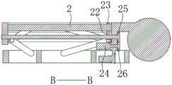
FIG. 7 is a schematic structural view taken along section B-B in FIG. 5;
FIG. 8 is a schematic structural view taken along section C-C of FIG. 5 in accordance with the present invention;
fig. 9 is a schematic structural view of a front sectional view after the angle of the fixing frame is adjusted according to the present invention.
In the figure: 1-fixed frame, 2-heat collecting tube, 3-water tank, 4-support frame, 5-first connecting rod, 6-second connecting rod, 7-first thread bushing, 8-third connecting rod, 9-fourth connecting rod, 10-second thread bushing, 11-rotating rod, 12-first external thread, 13-second external thread, 14-arc frame, 15-first gear, 16-first motor, 17-second gear, 18-toothed belt, 19-first fixed seat, 20-second fixed seat, 21-screw, 22-nut seat, 23-movable frame, 24-second motor, 25-fourth gear, 26-fifth gear and 27-rotating wheel.
Detailed Description
The technical solutions in the embodiments of the present invention will be clearly and completely described below with reference to the drawings in the embodiments of the present invention, and it is obvious that the described embodiments are only a part of the embodiments of the present invention, and not all of the embodiments. All other embodiments, which can be derived by a person skilled in the art from the embodiments given herein without making any creative effort, shall fall within the protection scope of the present invention.
Referring to fig. 1 to 9, the present invention provides a technical solution: the utility model provides a foldable solar collector, includes fixed frame 1, and 1 internal fixation of fixed frame has a plurality of thermal-collecting tubes 2, and the one end of fixed frame 1 is fixed with water tank 3, and the below of fixed frame 1 is provided with carriage 4, is provided with folding mechanism between carriage 4 and the fixed frame 1.
The folding mechanism comprises two first connecting rods 5, the lower ends of the two first connecting rods 5 are respectively hinged with two inner sides of the supporting frame 4 close to the front end of the supporting frame, the upper end of the first connecting rod 5 is hinged with a second connecting rod 6, the upper end of the second connecting rod 6 is hinged with the inner side of the fixed frame 1 close to the front end of the fixed frame, the outer side of the hinged part of the first connecting rod 5 and the second connecting rod 6 is hinged with a first threaded sleeve 7, the inner side of the supporting frame 4 close to the rear end of the supporting frame is hinged with a third connecting rod 8, the upper end of the third connecting rod 8 is hinged with a fourth connecting rod 9, the upper end of the fourth connecting rod 9 is hinged with the inner side of the fixed frame 1 close to the rear end of the fixed frame, the outer side of the hinged part of the third connecting rod 8 and the fourth connecting rod 9 is hinged with a second threaded sleeve 10, a rotating rod 11 is sleeved between the first threaded sleeve 7 and the second threaded sleeve 10, a first external thread 12 in threaded connection with the first threaded sleeve 7 is arranged on one section surface of the rotating rod 11 close to the first threaded sleeve 7, the other section surface that bull stick 11 is close to second thread bush 10 is provided with the second external screw thread 13 with second thread bush 10 threaded connection, and the pitch of second external screw thread 13 is greater than the pitch of first external screw thread 12, therefore when bull stick 11 rotational speed is certain, the distance of second thread bush 10 along the displacement on the second external screw thread 13 is far greater than the distance of first thread bush 7 along the last position of first external screw thread 12, and the one end that second thread bush 10 was worn out to two bull sticks 11 is provided with the first actuating mechanism who drives two bull sticks 11 pivoted simultaneously jointly. When the first driving mechanism drives the two rotating rods 11 to rotate clockwise simultaneously, because the distance of the displacement of the second threaded sleeve 10 along the second external thread 13 is far greater than the distance of the displacement of the first threaded sleeve 7 along the upper position of the first external thread 12, the first threaded sleeve 7 and the second threaded sleeve 10 move close to each other, then the fixing frame 1 can gradually rotate towards the direction away from the water tank 3, so that the inclination angle of the heat collecting tube 2 is increased, otherwise, when the first driving mechanism drives the two rotating rods 11 to simultaneously rotate, so that the first threaded sleeve 7 and the second threaded sleeve 10 move away from each other, then the fixing frame 1 can gradually rotate towards the direction of the water tank 3, so that the inclination angle of the heat collecting tube 2 is decreased, through the adjustment, the inclination angle of the heat collecting tube 2 can be adjusted, and further the heat efficiency is improved. Meanwhile, when the portable transportation device is used for transportation, the first driving mechanism drives the two rotating rods 11 to rotate reversely at the same time, so that the fixed frame 1 and the supporting frame 4 are gradually closed and folded, the size is reduced, and the portable transportation device is convenient to transport and carry.
First actuating mechanism includes arc frame 14, and arc frame 14 rotates the one end that wears out second thread bush 10 at two bull sticks 11, and first gear 15 is all installed to the one end that arc frame 14 was worn out to two bull sticks 11, and first motor 16 is installed to one side in the middle of arc frame 14, and first motor 16 adopts the low-speed motor, by the external power source power supply, and second gear 17 is installed to the axle head of first motor 16, and the transmission is connected between first gear 15 and the second gear 17.
Further, a rotating wheel 27 is rotated on the surface of the arc-shaped frame 14 on the upper side of the second gear 17, a toothed belt 18 is jointly transmitted among the first gear 15, the second gear 17 and the rotating wheel 27, and the first motor 16 can drive the two rotating rods 11 to rotate towards the same direction after being started by the cooperation of the first gear 15, the second gear 17, the toothed belt 18 and the rotating wheel 27.
The surface of the heat collecting pipe 2 is provided with a cleaning mechanism. Clean mechanism includes first fixing base 19 and second fixing base 20, first fixing base 19 is installed below in the middle of fixed frame 1 keeps away from the one end of water tank 3, second fixing base 20 is installed below in the middle of fixed frame 1 is close to the other end of water tank 3, it has screw rod 21 to rotate between first fixing base 19 and the second fixing base 20, screw rod 21's surperficial threaded connection has nut seat 22, the higher authority of nut seat 22 is fixed with removes frame 23, remove the fixed sponge of the inside pore wall of frame 23 and the surface sliding contact of each thermal-collecting tube 2, the one end of screw rod 21 is provided with drives its pivoted second actuating mechanism. The second driving mechanism drives the moving frame 23 to move, and the heat collecting pipes 2 are wiped and cleaned.
The second driving mechanism comprises a second motor 24, a fourth gear 25 is installed at one end of the screw rod 21 penetrating through the second fixing seat 20, the second motor 24 is installed on one side of the second fixing seat 20, a fifth gear 26 meshed with the fourth gear 25 is installed at the shaft end of the second motor 24, when the second motor 24 rotates in the forward direction, the fourth gear 25 is driven to rotate in the reverse direction, so that the movable frame 23 moves in the direction away from the water tank 3, otherwise, when the second motor 24 rotates in the reverse direction, the fourth gear 25 is driven to rotate in the forward direction, so that the movable frame 23 moves in the direction close to the water tank 3, the heat collecting tube 2 is cleaned in such a way, and the heat collecting tube 2 is better irradiated by light.
In this embodiment, the rotational fit is formed and may be realized by a bearing. For example, the arc frame 14 rotates at one end of the two rotating rods 11 penetrating through the second threaded sleeve 10, and the two rotating rods 11 can rotate on the arc frame 14 by embedding a bearing on the arc frame 14, and fixing the outer walls of the two rotating rods 11 with the axis of the bearing.
The working principle is as follows: during this foldable solar collector installation, first motor 16 is in the same direction as changeing, first gear 15, second gear 17 is in the same direction as changeing, two bull sticks 11 are in the same direction as changeing, because the distance of second thread bush 10 along the displacement on the second external screw thread 13 is far greater than the distance of first thread bush 7 along the position on first external screw thread 12, so first thread bush 7 is close to the motion with second thread bush 10, fixed frame 1 can be towards the direction rotation of keeping away from water tank 3 gradually then, make thermal-collecting tube 2 inclination grow this moment, it can to adjust suitable angle and stop.
When this foldable solar collector transports, first motor 16 reverses, and two bull sticks 11 reverse, so first thread bush 7 is the motion of keeping away from each other with second thread bush 10, then fixed frame 1 can be rotated towards the direction of water tank 3 gradually for the inclination diminishes at this moment to thermal-collecting tube 2, draws close gradually up to fixed frame 1 and carriage 4, folds up, reduces the volume, and convenient transportation is carried.
When this foldable solar collector is clean, when second motor 24 is in the same direction as changeing, drive fourth gear 25 and reverse, then remove frame 23 and remove towards the direction of keeping away from water tank 3, on the contrary when second motor 24 reverses, drive fourth gear 25 and in the same direction as changeing, then remove frame 23 and remove towards the direction of being close to water tank 3, clean through realizing cleaning to thermal-collecting tube 2 like this, ensure the better illumination that receives of thermal-collecting tube 2.
Although embodiments of the present invention have been shown and described, it will be appreciated by those skilled in the art that changes, modifications, substitutions and alterations can be made in these embodiments without departing from the principles and spirit of the invention, the scope of which is defined in the appended claims and their equivalents.
Claims (1)
1. The utility model provides a foldable solar collector, includes fixed frame (1), fixed frame (1) internal fixation has a plurality of thermal-collecting tubes (2), the one end of fixed frame (1) is fixed with water tank (3), its characterized in that: a supporting frame (4) is arranged below the fixed frame (1), and a folding mechanism is arranged between the supporting frame (4) and the fixed frame (1);
the folding mechanism comprises two first connecting rods (5), the lower ends of the two first connecting rods (5) are respectively hinged with two inner sides of the supporting frame (4) close to the front end of the supporting frame, the upper end of each first connecting rod (5) is hinged with a second connecting rod (6), the upper end of each second connecting rod (6) is hinged with the inner side of the fixed frame (1) close to the front end of the fixed frame, the outer sides of the hinged parts of the first connecting rods (5) and the second connecting rods (6) are hinged with a first threaded sleeve (7), the inner side of the supporting frame (4) close to the rear end of the supporting frame is hinged with a third connecting rod (8), the upper end of the third connecting rod (8) is hinged with a fourth connecting rod (9), the upper end of the fourth connecting rod (9) is hinged with the inner side of the fixed frame (1) close to the rear end of the fixed frame, the outer sides of the hinged parts of the third connecting rod (8) and the fourth connecting rod (9) are hinged parts are hinged with a second threaded sleeve (10), a rotating rod (11) is sleeved between the first threaded sleeve (7) and the second threaded sleeve (10), a first external thread (12) in threaded connection with the first threaded sleeve (7) is arranged on one section of surface, close to the first threaded sleeve (7), of the rotating rod (11), a second external thread (13) in threaded connection with the second threaded sleeve (10) is arranged on the other section of surface, close to the second threaded sleeve (10), of the rotating rod (11), and a first driving mechanism which drives the two rotating rods (11) to rotate simultaneously is arranged at one end, penetrating out of the second threaded sleeve (10), of the two rotating rods (11);
the pitch of the second external thread (13) is greater than the pitch of the first external thread (12);
the first driving mechanism comprises an arc-shaped frame (14), the arc-shaped frame (14) rotates at one end, penetrating out of the second threaded sleeve (10), of the two rotating rods (11), first gears (15) are mounted at one ends, penetrating out of the arc-shaped frame (14), of the two rotating rods (11), a first motor (16) is mounted at one side of the middle of the arc-shaped frame (14), a second gear (17) is mounted at the shaft end of the first motor (16), and the first gears (15) are in transmission connection with the second gears (17); a rotating wheel (27) is rotated on the surface of the arc-shaped frame (14) on the upper side of the second gear (17), and a toothed belt (18) is jointly transmitted among the first gear (15), the second gear (17) and the rotating wheel (27);
the surface of the heat collecting pipe (2) is provided with a cleaning mechanism; the cleaning mechanism comprises a first fixing seat (19) and a second fixing seat (20), the first fixing seat (19) is installed below the middle of one end, far away from the water tank (3), of the fixing frame (1), the second fixing seat (20) is installed below the middle of the other end, close to the water tank (3), of the fixing frame (1), a screw rod (21) is rotated between the first fixing seat (19) and the second fixing seat (20), a nut seat (22) is connected to the surface of the screw rod (21) in a threaded mode, a moving frame (23) is fixed on the nut seat (22), sponge fixed on the inner hole wall of the moving frame (23) is in sliding contact with the surface of each heat collecting pipe (2), and a second driving mechanism for driving the screw rod (21) to rotate is arranged at one end; the second driving mechanism comprises a second motor (24), the screw rod (21) penetrates out of one end of the second fixing seat (20) and is provided with a fourth gear (25), the second motor (24) is arranged on one side of the second fixing seat (20), and a fifth gear (26) meshed with the fourth gear (25) is arranged at the shaft end of the second motor (24).
Priority Applications (1)
| Application Number | Priority Date | Filing Date | Title |
|---|---|---|---|
| CN202010539637.3A CN111649495B (en) | 2020-06-15 | 2020-06-15 | Folding solar heat collector |
Applications Claiming Priority (1)
| Application Number | Priority Date | Filing Date | Title |
|---|---|---|---|
| CN202010539637.3A CN111649495B (en) | 2020-06-15 | 2020-06-15 | Folding solar heat collector |
Publications (2)
| Publication Number | Publication Date |
|---|---|
| CN111649495A CN111649495A (en) | 2020-09-11 |
| CN111649495B true CN111649495B (en) | 2021-11-26 |
Family
ID=72347882
Family Applications (1)
| Application Number | Title | Priority Date | Filing Date |
|---|---|---|---|
| CN202010539637.3A Active CN111649495B (en) | 2020-06-15 | 2020-06-15 | Folding solar heat collector |
Country Status (1)
| Country | Link |
|---|---|
| CN (1) | CN111649495B (en) |
Families Citing this family (2)
| Publication number | Priority date | Publication date | Assignee | Title |
|---|---|---|---|---|
| CN115182461A (en) * | 2022-07-14 | 2022-10-14 | 山东东珠新型房屋科技有限公司 | Passive mobile house |
| CN116105384B (en) * | 2023-04-12 | 2023-07-04 | 福建日晟户外用品有限公司 | Outdoor solar heater convenient to carry |
Citations (9)
| Publication number | Priority date | Publication date | Assignee | Title |
|---|---|---|---|---|
| CN203969669U (en) * | 2014-06-23 | 2014-12-03 | 包永永 | A kind of drawing table |
| CN208479550U (en) * | 2018-07-10 | 2019-02-05 | 瑞业(厦门)新能源有限公司 | A kind of aluminium alloy post automatically adjusting angle |
| CN109323468A (en) * | 2018-11-05 | 2019-02-12 | 江苏桑力太阳能产业有限公司 | A kind of solar water heater with absorbing pipe cleaner |
| CN208547127U (en) * | 2018-06-20 | 2019-02-26 | 南华大学 | A kind of solar energy hot plate with cleaning member structure |
| CN109962667A (en) * | 2017-12-14 | 2019-07-02 | 西安仁科电子科技有限公司 | A kind of solar panels multifunctional supporter |
| CN209134341U (en) * | 2018-12-24 | 2019-07-19 | 山东海德阳光太阳能有限公司 | A kind of balcony photovoltaic bracket |
| CN209910196U (en) * | 2018-12-27 | 2020-01-07 | 内蒙古晶新科技有限责任公司 | Automatic tracking vacuum tube heat collector |
| CN210183259U (en) * | 2019-06-19 | 2020-03-24 | 浙江广地建设工程有限公司 | Roof photovoltaic module installing support |
| CN210536562U (en) * | 2019-11-04 | 2020-05-15 | 丽瀑金属(江阴)有限公司 | Lightweight glass tile roof aluminum alloy photovoltaic support |
-
2020
- 2020-06-15 CN CN202010539637.3A patent/CN111649495B/en active Active
Patent Citations (9)
| Publication number | Priority date | Publication date | Assignee | Title |
|---|---|---|---|---|
| CN203969669U (en) * | 2014-06-23 | 2014-12-03 | 包永永 | A kind of drawing table |
| CN109962667A (en) * | 2017-12-14 | 2019-07-02 | 西安仁科电子科技有限公司 | A kind of solar panels multifunctional supporter |
| CN208547127U (en) * | 2018-06-20 | 2019-02-26 | 南华大学 | A kind of solar energy hot plate with cleaning member structure |
| CN208479550U (en) * | 2018-07-10 | 2019-02-05 | 瑞业(厦门)新能源有限公司 | A kind of aluminium alloy post automatically adjusting angle |
| CN109323468A (en) * | 2018-11-05 | 2019-02-12 | 江苏桑力太阳能产业有限公司 | A kind of solar water heater with absorbing pipe cleaner |
| CN209134341U (en) * | 2018-12-24 | 2019-07-19 | 山东海德阳光太阳能有限公司 | A kind of balcony photovoltaic bracket |
| CN209910196U (en) * | 2018-12-27 | 2020-01-07 | 内蒙古晶新科技有限责任公司 | Automatic tracking vacuum tube heat collector |
| CN210183259U (en) * | 2019-06-19 | 2020-03-24 | 浙江广地建设工程有限公司 | Roof photovoltaic module installing support |
| CN210536562U (en) * | 2019-11-04 | 2020-05-15 | 丽瀑金属(江阴)有限公司 | Lightweight glass tile roof aluminum alloy photovoltaic support |
Also Published As
| Publication number | Publication date |
|---|---|
| CN111649495A (en) | 2020-09-11 |
Similar Documents
| Publication | Publication Date | Title |
|---|---|---|
| CN111649495B (en) | Folding solar heat collector | |
| CN111365868A (en) | Optimize photovoltaic board fixing device of angle of sunshine | |
| CN111121310A (en) | Long-array double-shaft tracking heat pipe trough type solar heat collector | |
| CN109373608A (en) | A kind of adjustable type light-collected solar water heater and its adjusting method | |
| WO2013082872A1 (en) | Rotating solar power station that simultaneously tracks and concentrates sunlight | |
| CN211668051U (en) | Solar energy receiver | |
| CN108683396B (en) | Photovoltaic solar energy self-steering device | |
| CN110545069A (en) | solar photovoltaic module for improving light energy utilization rate | |
| CN212511875U (en) | Novel flat plate type solar heat collector | |
| CN114440471A (en) | Photovoltaic solar water heater integrated device | |
| CN221444505U (en) | Solar water heater with good heat collection effect | |
| CN219576987U (en) | Light photovoltaic photo-thermal composite board with panel cleaning structure | |
| CN220552114U (en) | Heat collector shielding device and heat collector | |
| CN220380003U (en) | Flat-plate solar water heater with flat-plate glass mirror for heat collection | |
| CN219018740U (en) | Large-angle mounting frame of photovoltaic module | |
| CN221081222U (en) | High-applicability fixing device for light Fu Qumian watts | |
| CN214315172U (en) | Position adjusting device for photovoltaic power generation | |
| CN220871157U (en) | Energy-saving solar energy circulation water heating equipment | |
| CN212627782U (en) | Mechanical device for adjusting solar telescopic rotation | |
| CN214064764U (en) | New forms of energy lighting device | |
| CN104329809B (en) | The adjustable double thermal energy conversion device of a kind of light | |
| CN219322324U (en) | Solar energy equipment installs construction auxiliary device | |
| CN219889791U (en) | Adjustable solar photovoltaic photo-thermal comprehensive utilization device | |
| CN220931406U (en) | Solar heat collector with high heat collection efficiency | |
| CN202350342U (en) | Solar boiler |
Legal Events
| Date | Code | Title | Description |
|---|---|---|---|
| PB01 | Publication | ||
| PB01 | Publication | ||
| SE01 | Entry into force of request for substantive examination | ||
| SE01 | Entry into force of request for substantive examination | ||
| GR01 | Patent grant | ||
| GR01 | Patent grant |