CN111608683A - High-precision and weldless curtain wall decorative plate mounting structure - Google Patents
High-precision and weldless curtain wall decorative plate mounting structure Download PDFInfo
- Publication number
- CN111608683A CN111608683A CN202010324731.7A CN202010324731A CN111608683A CN 111608683 A CN111608683 A CN 111608683A CN 202010324731 A CN202010324731 A CN 202010324731A CN 111608683 A CN111608683 A CN 111608683A
- Authority
- CN
- China
- Prior art keywords
- keel
- weldless
- precision
- curtain wall
- vertical
- Prior art date
- Legal status (The legal status is an assumption and is not a legal conclusion. Google has not performed a legal analysis and makes no representation as to the accuracy of the status listed.)
- Pending
Links
Images


Classifications
-
- E—FIXED CONSTRUCTIONS
- E21—EARTH DRILLING; MINING
- E21D—SHAFTS; TUNNELS; GALLERIES; LARGE UNDERGROUND CHAMBERS
- E21D11/00—Lining tunnels, galleries or other underground cavities, e.g. large underground chambers; Linings therefor; Making such linings in situ, e.g. by assembling
- E21D11/003—Linings or provisions thereon, specially adapted for traffic tunnels, e.g. with built-in cleaning devices
-
- E—FIXED CONSTRUCTIONS
- E21—EARTH DRILLING; MINING
- E21F—SAFETY DEVICES, TRANSPORT, FILLING-UP, RESCUE, VENTILATION, OR DRAINING IN OR OF MINES OR TUNNELS
- E21F17/00—Methods or devices for use in mines or tunnels, not covered elsewhere
-
- E—FIXED CONSTRUCTIONS
- E21—EARTH DRILLING; MINING
- E21F—SAFETY DEVICES, TRANSPORT, FILLING-UP, RESCUE, VENTILATION, OR DRAINING IN OR OF MINES OR TUNNELS
- E21F17/00—Methods or devices for use in mines or tunnels, not covered elsewhere
- E21F17/103—Dams, e.g. for ventilation
Abstract
The invention discloses a high-precision and weldless curtain wall decorative plate mounting structure, which comprises: the tunnel wall decoration plate comprises a vertical keel arranged on the side wall of the tunnel, a transverse keel connected to the vertical keel, and a decoration panel fixedly connected to the vertical keel and the transverse keel, wherein the vertical keel is of a U-shaped structure, and a U-shaped opening of the vertical keel faces the side wall of the tunnel; the side wall of the vertical keel is connected with an angle connector which is of a U-shaped structure, and the U-shaped bottom of the angle connector is fixedly connected to the side wall of the vertical keel; the transverse keel is of a U-shaped structure, and a U-shaped opening of the transverse keel faces the side wall of the tunnel; two ends of the transverse keel are sleeved outside the corner connectors or clamped on the corner connectors from inside; the vertical keels and/or the transverse keels are made of aluminum alloy materials. The invention provides the veneer which is convenient to install and better in visual guidance.
Description
Technical Field
The invention belongs to the field of architectural decoration, and particularly relates to a high-precision and weldless curtain wall decorative plate mounting structure.
Background
The traditional technical scheme is that a cement board and a steel frame are connected into a firm whole in a back-attached steel frame mode and then hung on a main steel frame in a groove-in mode.
However, this process has many drawbacks: 1. the scene needs a large amount of fire welding processes, and is strict to on-the-spot safe fire prevention requirement, and on-the-spot welding needs to spend a large amount of time and manual work and fire prevention measure moreover, and the support of steel construction has great material deformation along with the span increase, leads to appearing the height drop. 2. The installation procedures of the on-site keel are multiple, and the installation and connection modes are complex. 3. The material variety is various and has no choice, and the restriction is great under the condition that the material supply of a certain specification is delayed and the installation and production speed needs to be accelerated on site. 4. The construction process has great restriction on highway tunnels and underground buildings, and cannot realize long-distance continuous construction.
Disclosure of Invention
The invention provides a high-precision and welding-free curtain wall decorative plate mounting structure aiming at the problems in the prior art, and partial embodiments of the invention can solve the problems.
In order to achieve the purpose, the invention adopts the following technical scheme:
a high accuracy, solderless curtain decorative panel mounting structure, the mounting structure includes: the tunnel wall decoration plate comprises a vertical keel arranged on the side wall of the tunnel, a transverse keel connected to the vertical keel, and a decoration panel fixedly connected to the vertical keel and the transverse keel, wherein the vertical keel is of a U-shaped structure, and a U-shaped opening of the vertical keel faces the side wall of the tunnel; the side wall of the vertical keel is connected with an angle connector which is of a U-shaped structure, and the U-shaped bottom of the angle connector is fixedly connected to the side wall of the vertical keel; the transverse keel is of a U-shaped structure, and a U-shaped opening of the transverse keel faces the side wall of the tunnel; two ends of the transverse keel are sleeved outside the corner connectors or clamped on the corner connectors from inside; the vertical keels and/or the transverse keels are made of aluminum alloy materials.
Preferably, the bottom of the vertical keel is fixed in the anti-collision protective wall, the middle part and the upper part of the vertical keel are respectively and fixedly connected with one end of a support connecting rod, and the other end of the support connecting rod is fixedly connected on the side wall of the tunnel.
Preferably, the distance between two adjacent vertical keels is smaller than or equal to 650 mm.
Preferably, the cross keels and the vertical keels form a plurality of quadrilateral partitions, and the veneer comprises a plurality of sub-panels arranged on the partitions in an array manner.
Preferably, the sub-panel is a fiber cement panel.
Preferably, be provided with a plurality of structural adhesives on vertical keel and the horizontal keel, the daughter board passes through structural adhesive bonds on horizontal keel and vertical keel.
Preferably, the distance between adjacent structural adhesives is about 400mm, the length of the structural adhesive is greater than 100mm, and the structural adhesive is a silicone structural sealant with medium and high modulus.
Preferably, a lengthened connecting rod is arranged at the concave position of the side wall of the tunnel, one end of the lengthened connecting rod is fixedly connected at the concave position of the side wall of the tunnel, and the other end of the lengthened connecting rod is fixedly connected at the top of the vertical keel.
Preferably, a groove-shaped buckle strip is arranged at a seam between the adjacent daughter boards, the edges of two sides of the buckle strip are pressed against the edges of the daughter boards, and the bottom of the buckle strip is sunk into the seam.
Preferably, the notch of the fastening strip is provided with a step opening, and an elastic protruding strip is arranged inside the notch of the fastening strip.
Preferably, the groove-shaped pressing strip is clamped on the buckle strip, the top of the pressing strip is provided with racks extending towards two sides, the racks are abutted against the protruding strip, and the cover edge arranged at the bottom of the pressing strip is abutted against the step opening.
Preferably, the adhesive tape is attached to the cross keel, and the adhesive tape is clamped between the cross keel and the bottom of the buckling strip.
Preferably, the height of the adhesive tape is equal to the gap between the bottom of the buckle strip and the cross keel.
Preferably, the adhesive tape is made of polyethylene, and the screws sequentially penetrate through the bottom of the buckling strip and the adhesive tape and then are in threaded connection with the transverse keel.
Preferably, the bottom of the mounting structure is provided with a lower keel, the lower keel is provided with an upward notch, and the bottom of the veneer is inserted into the lower keel.
Preferably, the sub-board is rectangular and/or diamond-shaped.
Compared with the prior art, the invention has the beneficial effects that:
firstly, according to the characteristics of tunnel underground engineering: the structure has large underground moisture, a plurality of water seepage points and poor air circulation in the construction process, all keel materials are prefabricated and processed in a processing plant after rechecking according to drawings and on-site setting, the keel installation adopts bolt connection, namely assembly installation, the optimized scheme of installation cancels the steel framework welding process scheme, the customized type adjustable hot galvanizing angle code (40: 54: 40: 3), the support connecting rod (50: 5 mm) and the aluminum keel bracket are adopted, the aluminum keel has light weight and is installed by carrying, the height error of every 6m of the aluminum material is less than 0.5mm, and the accumulated error is almost 0;
secondly, an aluminum alloy keel is assembled and then connected with a mounting scheme, each aluminum vertical keel is provided with more than 2 sets of adjustable hot galvanizing angle codes and support connecting rods for reliable connection and fixation, each transverse keel spans no more than 600mm, the height of each vertical keel is about 3m, and three points and two supports are adopted for fixation;
thirdly, continuous PE adhesive tapes are pasted on the lower aluminum alloy keel and the L-shaped keel, dotted structural adhesive is applied (the structural adhesive is silicone structural sealant with medium and high modulus, one point is arranged every 400mm, the length of each point is not less than 100mm, so that the tensile bonding strength is larger than 5 Mpa), a fiber cement plate (1200 x 2400 mm) is transversely installed, the lower end of the plate is inserted into the lower aluminum alloy keel, the verticality is adjusted, the plate is tightly pressed on the keel, then aluminum alloy buckling strips and pressing strips are pressed at the upper end of the carbon gray fiber cement plate, stainless steel countersunk self-drilling screws are fixed on the transverse keel at the through groove of the aluminum alloy pressing strip, and a stainless steel countersunk self-drilling screw is arranged at the 400mm interval to strengthen the reliable connection between the panel and the keel.
Drawings
In order to more clearly illustrate the embodiments of the present invention or the technical solutions in the prior art, the drawings used in the description of the embodiments or the prior art will be briefly described below, it is obvious that the drawings in the following description are only some embodiments of the present invention, and for those skilled in the art, other drawings can be obtained according to the drawings without creative efforts.
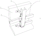
Figure 1 is a schematic view of a center keel support according to an embodiment of the invention.
Fig. 2 is a schematic view of the cross runners and the vertical runners connected by corner connectors according to an embodiment of the present invention.
FIG. 3 is a schematic, partially cut-away view of a veneer in an embodiment of the invention.
FIG. 4 is a cross-sectional view of a screw connection at a fastening strip according to an embodiment of the present invention.
Detailed Description
The technical solutions in the embodiments of the present invention will be clearly and completely described below with reference to the drawings in the embodiments of the present invention, and it is obvious that the described embodiments are only a part of the embodiments of the present invention, and not all of the embodiments. All other embodiments, which can be obtained by a person skilled in the art without inventive effort based on the embodiments of the present invention, are within the scope of the present invention.
In the description of the present invention, it is to be understood that the terms "longitudinal", "lateral", "upper", "lower", "front", "rear", "left", "right", "vertical", "horizontal", "top", "bottom", "inner", "outer", and the like, indicate orientations or positional relationships based on those shown in the drawings, and are used merely for convenience of description and for simplicity of description, and do not indicate or imply that the referenced devices or elements must have a particular orientation, be constructed in a particular orientation, and be operated, and thus, are not to be construed as limiting the present invention.
As shown in fig. 1 to 4, the present embodiment provides a high-precision, weldless curtain wall decorative panel mounting structure, which includes: install vertical keel 1 at tunnel lateral wall 5, connect horizontal keel 2, the decorative board of fixed connection on vertical keel 1 and horizontal keel 2 on vertical keel 1, vertical keel 1 keeps vertical when tunnel road surface fluctuates.
The bottom of the vertical keel 1 is fixed in the anti-collision protective wall 3, the middle part and the upper part of the vertical keel 1 are respectively and fixedly connected with one end of a support connecting rod 4, and the other end of the support connecting rod 4 is fixedly connected on the side wall 5 of the tunnel.
The vertical keel 1 is of a U-shaped structure, and the U-shaped opening of the vertical keel 1 faces the side wall 5 of the tunnel; the side wall of the vertical keel 1 is connected with an angle connector 6, the angle connector 6 is of a U-shaped structure, and the U-shaped bottom of the angle connector 6 is fixedly connected to the side wall of the vertical keel 1; the transverse keel 2 is of a U-shaped structure, and a U-shaped opening of the transverse keel 2 faces the side wall 5 of the tunnel; the two ends of the transverse keel 2 are arranged outside the outer sleeve or clamped on the corner connector 6 from inside.
The vertical keel 1 and/or the transverse keel 2 are/is made of aluminum alloy material.
The distance between two adjacent vertical keels 1 is less than or equal to 650 mm.
The cross keels 2 and the vertical keels 1 form a plurality of quadrilateral partitions 7, and the veneer comprises a plurality of sub-boards 8 arranged on the partitions 7 in an array mode.
The sub-plate 8 is a fiber cement plate.
The distance between the adjacent structural adhesives 9 is about 400mm, the length of the structural adhesive 9 is more than 100mm, and the structural adhesive 9 is a silicone structural sealant with medium and high modulus.
A lengthened connecting rod 11 is arranged at a concave part 10 of the tunnel side wall 5, one end of the lengthened connecting rod 11 is fixedly connected at the concave part 10 of the tunnel side wall 5, and the other end of the lengthened connecting rod 11 is fixedly connected at the top of the vertical keel 1.
A groove-shaped buckle strip 12 is arranged at the seam between the adjacent daughter boards 8, the edges of two sides of the buckle strip 12 are pressed against the edges of the daughter boards 8, and the bottom of the buckle strip 12 sinks into the seam.
The notch of the buckling strip 12 is provided with a step opening 13, and an elastic protruding strip 14 is arranged inside the notch of the buckling strip 12.
The groove-shaped pressing strip 15 is clamped on the buckle strip 12, the top of the pressing strip 15 is provided with a rack 16 extending towards two sides, the rack 16 is abutted against the protruding strip 14, and a cover edge 17 arranged at the bottom of the pressing strip 15 is abutted against the stepped opening 13.
The adhesive tape 19 is attached to the cross keel 2, and the adhesive tape 19 is clamped between the cross keel 2 and the bottom of the buckling strip 12. The adhesive tape makes and does not have the space between profile buckle bottom and the cross keel, and the profile buckle that the wind pressure change leads to in the tunnel that has avoided the space to lead to is not hard up.
The height of the adhesive tape 19 is equal to the gap between the bottom of the fastening strip and the cross keel.
The adhesive tape 19 is made of polyethylene, and the screws sequentially penetrate through the bottom of the buckle strip 12 and the adhesive tape 19 and are connected in the cross keel 2 in a threaded mode. The rubber strip of the PE material has good durability and meets the service life of fifteen years.
The mounting structure bottom is provided with lower keel 18, and lower keel 18 is provided with ascending notch, and the bottom of decorative board is pegged graft in lower keel 18.
The daughter boards 8 are rectangular and/or rhomboidal. When tunnel road surface appears and fluctuates from top to bottom, anticollision revetment also has certain inclination along with the road surface, and the vertical keel still is perpendicular to the horizontal plane installation this moment, leads to the district to separate and becomes the rhombus, so adopts the daughter board of rhombus. By adopting the structure, the curve of the whole veneer can be smoothly transited along with the undulation of the road surface, and better visual guidance is provided for a vehicle owner.
A mounting method of a high-precision and weldless curtain wall decorative plate mounting structure comprises the following steps: installing a vertical keel 1 which keeps vertical; a transverse keel 2 is connected between the vertical keels 1; adhering structural adhesive 9 and adhesive tape 19 on the transverse keel 2 and the vertical keel 1; carbon gray fiber cement boards are bonded on a plurality of quadrilateral partitions 7 formed by the transverse keels 2 and the vertical keels 1; the aluminum alloy buckle strip 12 is clamped in a seam formed by adjacent fiber cement boards; the bottom of the buckling strip 12, the adhesive tape 19 and the transverse keel 2 are fixedly connected together in sequence through stainless steel countersunk self-drilling screws; the aluminum alloy bead 15 is snapped into the notch of the buckle strip 12.
The novel curtain wall fiber cement board of KTC can realize the effect that other materials can not be realized because of its peculiar fire-proof insulation, dampproofing and waterproofing, thermal-insulated sound insulation, matter are light, excel in, green, the various rich colors of pattern, other performances such as interlaminar displacement performance, and is widely used in power plant, chemical industry enterprise, highway tunnel, underground facilities, commercial building, house, hotel and other public places indoor and outdoor decoration and curtain wall building at home and abroad in recent years.
Characteristics and advantages of KTC fiber cement board
Fireproof insulation: the non-combustible A-grade insulating material has the advantages of no combustion of the board in case of fire, no generation of toxic smoke, low conductivity coefficient and ideal insulating material.
Waterproof and moistureproof: can maintain stable performance and does not sink or deform in the open air and high humidity environment. The service life of the KTC is up to more than 25 years (the service life of the common cement board is less than 15 years), the surface color can be sprayed again to look fresh, the KTC is acid and alkali resistant and corrosion resistant, the KTC is not damaged by moisture or insects and ants, the strength and the hardness are enhanced along with the time, and the ultra-long service life is ensured.
Thirdly, heat and sound insulation: low heat conductivity coefficient, good heat insulation performance, high product density and good sound insulation.
Fourthly, the weight is light and the strength is high: the plate pressed by the 5000-ton flat plate oil press has high strength and is not easy to deform and warp.
Green environmental protection: adopts a zero asbestos formula, has no radioactivity, and is a green environment-friendly building material product.
Sixthly, patterns are various and colors are rich: the surface coating colors of various patterns are combined randomly, the colors are rich, and a wide creative space is provided for designers.
The patterns are various and the color is rich: the surface coating colors of various patterns are combined randomly, the colors are rich, and a wide creative space is provided for designers.
Although the present invention has been described in detail with respect to the above embodiments, it will be understood by those skilled in the art that modifications or improvements based on the disclosure of the present invention may be made without departing from the spirit and scope of the invention, and these modifications and improvements are within the spirit and scope of the invention.
Claims (16)
1. A high accuracy, solderless curtain decorative panel mounting structure, the mounting structure includes: the decorative plate is characterized in that the vertical keel is of a U-shaped structure, and a U-shaped opening of the vertical keel faces the side wall of the tunnel; the side wall of the vertical keel is connected with an angle connector which is of a U-shaped structure, and the U-shaped bottom of the angle connector is fixedly connected to the side wall of the vertical keel; the transverse keel is of a U-shaped structure, and a U-shaped opening of the transverse keel faces the side wall of the tunnel; two ends of the transverse keel are sleeved outside the corner connectors or clamped on the corner connectors from inside; the vertical keels and/or the transverse keels are made of aluminum alloy materials.
2. The high-precision, weldless curtain wall decorative plate installation structure of claim 1, wherein the bottom of the vertical keel is fixed in the anti-collision protective wall, the middle part and the upper part of the vertical keel are respectively and fixedly connected with one end of a support connecting rod, and the other end of the support connecting rod is fixedly connected to the side wall of the tunnel.
3. The high-precision, weldless curtain wall trim panel mounting structure of claim 1, wherein a distance between two adjacent ones of said mullions is 650mm or less.
4. The high-precision, weldless curtain wall trim panel mounting structure of claim 1, wherein the cross runners and the vertical runners form a plurality of quadrilateral partitions, and the trim panel includes a plurality of sub-panels arranged in an array on the partitions.
5. The high-precision, weldless curtain wall trim panel mounting structure of claim 4, wherein the sub-panel is a fiber cement panel.
6. The high-precision, weldless curtain wall decorative plate mounting structure of claim 4, wherein a plurality of structural adhesives are arranged on the vertical keel and the horizontal keel, and the sub-plate is bonded on the horizontal keel and the vertical keel through the structural adhesives.
7. The high-precision, weldless curtain wall decorative panel installation structure of claim 6, wherein the distance between adjacent structural adhesives is about 400mm, the length of the structural adhesive is greater than 100mm, and the structural adhesive is a medium-high modulus silicone structural sealant.
8. The high-precision, weldless curtain wall decorative panel installation structure of claim 1, wherein an elongated connecting rod is arranged at the recess of the tunnel side wall, one end of the elongated connecting rod is fixedly connected at the recess of the tunnel side wall, and the other end of the elongated connecting rod is fixedly connected at the top of the vertical keel.
9. The high-precision and weldless curtain wall decorative plate installation structure of claim 6, wherein a groove-shaped buckling strip is arranged at a seam between adjacent sub-plates, two side edges of the buckling strip are pressed against the edges of the sub-plates, and the bottom of the buckling strip is sunk into the seam.
10. The high-precision, weldless curtain wall decorative panel installation structure of claim 9, wherein the notch of said fastening strip is provided with a stepped opening, and an elastic protruding strip is provided inside the notch of said fastening strip.
11. The high-precision and weldless curtain wall decorative plate installation structure of claim 10, wherein a groove-shaped pressing strip is clamped on the buckling strip, a rack extending towards two sides is arranged at the top of the pressing strip, the rack is abutted with the protruding strip, and a cover edge arranged at the bottom of the pressing strip is abutted on the stepped opening.
12. The high-precision, weldless curtain wall decorative panel installation structure of claim 9, wherein an adhesive tape is attached to the cross keel, and the adhesive tape is clamped between the cross keel and the bottom of the buckling strip.
13. The high precision, weldless curtain wall trim panel mounting arrangement of claim 12, wherein the height of the glue strip is equal to the gap between the bottom of the profile and the cross runner.
14. The high-precision, weldless curtain wall decorative panel installation structure of claim 13, wherein the adhesive tape is made of polyethylene, and the screws sequentially penetrate through the bottom of the fastening strip and are screwed into the cross keels after passing through the adhesive tape.
15. The high-precision, weldless curtain wall decorative panel installation structure of claim 1, wherein a lower keel is provided at the bottom of the installation structure, the lower keel is provided with an upward notch, and the bottom of the decorative panel is inserted into the lower keel.
16. The high-precision, weldless curtain wall trim panel mounting structure of claim 4, wherein the sub-panels are rectangular and/or diamond-shaped.
Priority Applications (1)
| Application Number | Priority Date | Filing Date | Title |
|---|---|---|---|
| CN202010324731.7A CN111608683A (en) | 2020-04-23 | 2020-04-23 | High-precision and weldless curtain wall decorative plate mounting structure |
Applications Claiming Priority (1)
| Application Number | Priority Date | Filing Date | Title |
|---|---|---|---|
| CN202010324731.7A CN111608683A (en) | 2020-04-23 | 2020-04-23 | High-precision and weldless curtain wall decorative plate mounting structure |
Publications (1)
| Publication Number | Publication Date |
|---|---|
| CN111608683A true CN111608683A (en) | 2020-09-01 |
Family
ID=72204681
Family Applications (1)
| Application Number | Title | Priority Date | Filing Date |
|---|---|---|---|
| CN202010324731.7A Pending CN111608683A (en) | 2020-04-23 | 2020-04-23 | High-precision and weldless curtain wall decorative plate mounting structure |
Country Status (1)
| Country | Link |
|---|---|
| CN (1) | CN111608683A (en) |
Cited By (1)
| Publication number | Priority date | Publication date | Assignee | Title |
|---|---|---|---|---|
| CN113700497A (en) * | 2021-09-27 | 2021-11-26 | 苏州美瑞德建筑装饰有限公司 | Modular clamping installation design structure of arc-shaped aluminum plate for rail transit |
Citations (7)
| Publication number | Priority date | Publication date | Assignee | Title |
|---|---|---|---|---|
| CN201649374U (en) * | 2010-01-15 | 2010-11-24 | 深圳市方大装饰工程有限公司 | Framework type curtain wall with decorative strip keels |
| CN202359705U (en) * | 2011-11-11 | 2012-08-01 | 沈阳远大铝业工程有限公司 | Connecting piece of curtain wall glass plates |
| CN203160582U (en) * | 2013-02-01 | 2013-08-28 | 佛山澳特板业有限公司 | Transverse pressing strip interior-casing-free wall space system capable of being installed rapidly |
| CN203626854U (en) * | 2013-11-28 | 2014-06-04 | 佛山澳特板业有限公司 | Tunnel stand column mounting system |
| CN105040950A (en) * | 2015-06-30 | 2015-11-11 | 苏州金螳螂建筑装饰股份有限公司 | Stone dry bonding mounting structure unit and mounting method thereof |
| CN107254928A (en) * | 2017-07-31 | 2017-10-17 | 中国冶集团有限公司 | A kind of hidden frame glass curtain and its method of construction without secondary frame and underframe |
| CN209837410U (en) * | 2019-03-27 | 2019-12-24 | 上海方大勍瓴科技有限公司 | Frame curtain wall erection joint structure in entrance to a cave and system thereof |
-
2020
- 2020-04-23 CN CN202010324731.7A patent/CN111608683A/en active Pending
Patent Citations (7)
| Publication number | Priority date | Publication date | Assignee | Title |
|---|---|---|---|---|
| CN201649374U (en) * | 2010-01-15 | 2010-11-24 | 深圳市方大装饰工程有限公司 | Framework type curtain wall with decorative strip keels |
| CN202359705U (en) * | 2011-11-11 | 2012-08-01 | 沈阳远大铝业工程有限公司 | Connecting piece of curtain wall glass plates |
| CN203160582U (en) * | 2013-02-01 | 2013-08-28 | 佛山澳特板业有限公司 | Transverse pressing strip interior-casing-free wall space system capable of being installed rapidly |
| CN203626854U (en) * | 2013-11-28 | 2014-06-04 | 佛山澳特板业有限公司 | Tunnel stand column mounting system |
| CN105040950A (en) * | 2015-06-30 | 2015-11-11 | 苏州金螳螂建筑装饰股份有限公司 | Stone dry bonding mounting structure unit and mounting method thereof |
| CN107254928A (en) * | 2017-07-31 | 2017-10-17 | 中国冶集团有限公司 | A kind of hidden frame glass curtain and its method of construction without secondary frame and underframe |
| CN209837410U (en) * | 2019-03-27 | 2019-12-24 | 上海方大勍瓴科技有限公司 | Frame curtain wall erection joint structure in entrance to a cave and system thereof |
Cited By (2)
| Publication number | Priority date | Publication date | Assignee | Title |
|---|---|---|---|---|
| CN113700497A (en) * | 2021-09-27 | 2021-11-26 | 苏州美瑞德建筑装饰有限公司 | Modular clamping installation design structure of arc-shaped aluminum plate for rail transit |
| CN113700497B (en) * | 2021-09-27 | 2024-01-16 | 苏州美瑞德建筑装饰有限公司 | A modular joint installation design structure for arc aluminum plate of track traffic |
Similar Documents
| Publication | Publication Date | Title |
|---|---|---|
| CN202164723U (en) | Hollow light steel keel straw plate partition wall | |
| FI73040B (en) | ELEMENT FOER UTVAENDIG TILLAEGGSOLOLING. | |
| CN111608683A (en) | High-precision and weldless curtain wall decorative plate mounting structure | |
| CN113823200A (en) | Decorative three-dimensional lamp box structure and construction method thereof | |
| CN212562266U (en) | Decorative board mounting structure with continuous decorative lines in tunnel | |
| CN213509344U (en) | Tunnel lateral wall decorative board mounting structure convenient to installation | |
| CN213510630U (en) | Mounting structure suitable for novel fiber cement decorative board curtain system | |
| CN212427685U (en) | Energy-saving curtain wall with waterproof insulation structure | |
| CN111608682A (en) | Durable, wear-resisting mounting structure of novel curtain decorative board | |
| CN111577323A (en) | Mounting structure and mounting method for decorative plate in tunnel | |
| CN214785280U (en) | Swift bayonet fiber cement wallboard of assembly of environmental protection | |
| CN110629913A (en) | Curtain wall structure adopting red brick decoration panel and construction method thereof | |
| CN211774828U (en) | Multifunctional light steel keel and partition wall | |
| CN111305430A (en) | Metal wallboard and curtain wall with same | |
| CN111075056A (en) | Multifunctional light steel keel and partition wall | |
| CN213682951U (en) | Novel fireproof building board | |
| CN114439149B (en) | Wallboard for building assembly type enclosure structure | |
| CN210827985U (en) | Waterproof device for curtain wall | |
| CN216920878U (en) | Stepped stone curtain wall structure | |
| CN220725503U (en) | Shelve formula installation plate-type furred ceiling system | |
| CN216075904U (en) | Modular wallboard structure | |
| CN217580972U (en) | Energy-conserving outer wall wallboard for building | |
| CN216446411U (en) | Mounting structure of decorative hanging plate | |
| CN219316133U (en) | Internally and externally assembled integrated metal surface composite heat-insulating curtain wall | |
| CN214302403U (en) | Partition wall system is decorated to assembled |
Legal Events
| Date | Code | Title | Description |
|---|---|---|---|
| PB01 | Publication | ||
| PB01 | Publication | ||
| SE01 | Entry into force of request for substantive examination | ||
| SE01 | Entry into force of request for substantive examination | ||
| RJ01 | Rejection of invention patent application after publication |
Application publication date: 20200901 |
|
| RJ01 | Rejection of invention patent application after publication |