CN111554211A - Backlight source of light-emitting vehicle sign and light-emitting vehicle sign - Google Patents
Backlight source of light-emitting vehicle sign and light-emitting vehicle sign Download PDFInfo
- Publication number
- CN111554211A CN111554211A CN202010461568.9A CN202010461568A CN111554211A CN 111554211 A CN111554211 A CN 111554211A CN 202010461568 A CN202010461568 A CN 202010461568A CN 111554211 A CN111554211 A CN 111554211A
- Authority
- CN
- China
- Prior art keywords
- light
- backlight
- light emitting
- optical panel
- emitting element
- Prior art date
- Legal status (The legal status is an assumption and is not a legal conclusion. Google has not performed a legal analysis and makes no representation as to the accuracy of the status listed.)
- Pending
Links
Images


Classifications
-
- G—PHYSICS
- G09—EDUCATION; CRYPTOGRAPHY; DISPLAY; ADVERTISING; SEALS
- G09F—DISPLAYING; ADVERTISING; SIGNS; LABELS OR NAME-PLATES; SEALS
- G09F13/00—Illuminated signs; Luminous advertising
- G09F13/04—Signs, boards or panels, illuminated from behind the insignia
- G09F13/0404—Signs, boards or panels, illuminated from behind the insignia the light source being enclosed in a box forming the character of the sign
-
- B—PERFORMING OPERATIONS; TRANSPORTING
- B60—VEHICLES IN GENERAL
- B60R—VEHICLES, VEHICLE FITTINGS, OR VEHICLE PARTS, NOT OTHERWISE PROVIDED FOR
- B60R13/00—Elements for body-finishing, identifying, or decorating; Arrangements or adaptations for advertising purposes
- B60R13/005—Manufacturers' emblems, name plates, bonnet ornaments, mascots or the like; Mounting means therefor
-
- G—PHYSICS
- G09—EDUCATION; CRYPTOGRAPHY; DISPLAY; ADVERTISING; SEALS
- G09F—DISPLAYING; ADVERTISING; SIGNS; LABELS OR NAME-PLATES; SEALS
- G09F13/00—Illuminated signs; Luminous advertising
- G09F13/04—Signs, boards or panels, illuminated from behind the insignia
- G09F13/0413—Frames or casing structures therefor
-
- G—PHYSICS
- G09—EDUCATION; CRYPTOGRAPHY; DISPLAY; ADVERTISING; SEALS
- G09F—DISPLAYING; ADVERTISING; SIGNS; LABELS OR NAME-PLATES; SEALS
- G09F13/00—Illuminated signs; Luminous advertising
- G09F13/04—Signs, boards or panels, illuminated from behind the insignia
- G09F13/0418—Constructional details
Landscapes
- Engineering & Computer Science (AREA)
- Physics & Mathematics (AREA)
- General Physics & Mathematics (AREA)
- Theoretical Computer Science (AREA)
- Mechanical Engineering (AREA)
- Vehicle Waterproofing, Decoration, And Sanitation Devices (AREA)
- Illuminated Signs And Luminous Advertising (AREA)
Abstract
The utility model provides a backlight of car sign that can give out light, the car sign includes the car logo, the backlight upper surface is used for the installation the car logo, the backlight includes light emitting component and optical panel, light emitting component includes light emitting component, optical panel is located the light emitting component top, optical panel is equipped with and is located directly over light emitting component in order to shelter from the reflection the shielding layer of the partial light of light emitting component transmission. The invention also discloses a luminous vehicle sign comprising the backlight source. According to the backlight source of the luminous vehicle sign and the luminous vehicle sign provided by the invention, the shielding layer which is positioned right above the light-emitting element and used for shielding and reflecting part of light rays emitted by the light-emitting element is arranged on the optical panel, so that the luminous vehicle sign has high brightness, high uniformity and high reliability, and finally, the luminous vehicle sign is high in identification and increased in aesthetic feeling.
Description
Technical Field
The invention relates to the technical field of automobiles, in particular to a backlight source of a luminous vehicle sign and the luminous vehicle sign.
Background
Along with the improvement of the functions and the aesthetics of automobiles, automobile brand car logos are developed to be diversified and personalized at present, particularly, the popularization of new energy automobiles drives, and from the aspects of functional requirements and safety, the traditional automobile brand car logos cannot meet various requirements of people, for example, the charging working state of a new energy automobile cannot be visually indicated outside the automobile, the daytime running light function running indication cannot be made, and the automobile brand cannot be identified or is difficult to identify when the automobile is running at night. With the development of the technology and the improvement of the demand, the luminous car logo slowly enters the sight of people, but because the car logo and the light emission are product integration in two fields, the luminous car logo on some markets at present has single function (for example, only one color), low brightness and poor light emission uniformity, so that the identification degree is still low, the aesthetic degree is poor, and the good effect is not achieved even if much cost is spent.
The foregoing description is provided for general background information and is not admitted to be prior art.
Disclosure of Invention
The invention aims to provide a backlight source of a light-emitting vehicle sign and the light-emitting vehicle sign, which can bring high identification to the vehicle sign and increase aesthetic feeling.
The invention provides a backlight source of a luminous vehicle logo, which comprises a vehicle logo, wherein the upper surface of the backlight source is used for mounting the vehicle logo, the backlight source comprises a light-emitting component and an optical panel, the light-emitting component comprises a light-emitting element, the optical panel is positioned above the light-emitting component, and the optical panel is provided with a shielding layer which is positioned right above the light-emitting element and used for shielding and reflecting part of light rays emitted by the light-emitting element.
Further, the shielding layer is formed by an optical ink micro-point printing process.
Furthermore, the shielding layer is a plurality of shielding point combinations, the light emitting assembly comprises a plurality of light emitting elements, each light emitting element corresponds to one shielding point combination, and one shielding point combination is arranged from the center of the corresponding light emitting element to the outside from dense to sparse.
Further, the optical ink is white oil.
Furthermore, the light-emitting component corresponds to one LED lamp, the light-emitting component further comprises a PCB, a plurality of first bonding pads and a second bonding pad far away from the first bonding pads are arranged on the front surface of the PCB, each LED lamp is attached to one first bonding pad, and the second bonding pad is used for welding a power supply line or a connecting seat.
Further, the optical panel is a diffusion plate for optically diffusing the light emitted from the light emitting element.
Further, the backlight source further comprises a frame for bearing the light-emitting assembly and the emblem, the light-emitting assembly is fixed at the bottom of the frame, the optical panel is installed at the top of the frame, and the emblem is installed above the frame.
Furthermore, the frame comprises a horizontal part, the horizontal part is provided with a through hole, the through hole gradually increases from the bottom surface of the horizontal part to the top surface, and the light-emitting element is exposed from the through hole.
Further, the frame comprises a blocking wall part formed by vertically extending the horizontal part, and the blocking wall part corresponds to the distribution shape of the light-emitting elements.
The invention also provides a luminous car logo which comprises a car logo and the backlight source, wherein the car logo is arranged on the upper surface of the backlight source.
The backlight source of the luminous vehicle sign and the luminous vehicle sign provided by the invention have the advantages that the shielding layer which is arranged right above the light-emitting element and used for shielding and reflecting part of light rays emitted by the light-emitting element is arranged on the optical panel, so that the luminous vehicle sign has high brightness, high uniformity and high reliability, and finally, the luminous vehicle sign is high in identification and attractive in appearance.
Drawings
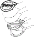
Fig. 1 is an exploded view of the entire structure of a luminescent car logo according to an embodiment of the present invention.
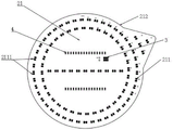
Fig. 2 is a schematic view of a structure of a light emitting element of the backlight of the light-emitting vehicular sign shown in fig. 1.
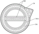
Fig. 3 is a schematic structural diagram of a frame of a backlight source of the light-emitting vehicle sign shown in fig. 1.
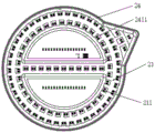
Fig. 4 is a combination diagram of a light-emitting assembly and a frame of the backlight source of the light-emitting vehicle sign shown in fig. 1.
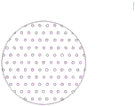
Fig. 5 is a schematic front view of a backlight of the light-emitting vehicular sign shown in fig. 1.
FIG. 6 is a close-up view of the first embodiment of the barrier layer shown in FIG. 5 at circle A.
FIG. 7 is a close-up view of a second embodiment of the barrier layer shown in FIG. 5 and taken at circle A.
Fig. 8 is a schematic view of the back side of the backlight of the light-emitting vehicular sign shown in fig. 1.
Fig. 9 is a schematic view of the combination of the whole structure of the light-emitting car logo plate shown in fig. 1.
Detailed Description
The following detailed description of embodiments of the present invention is provided in connection with the accompanying drawings and examples. The following examples are intended to illustrate the invention but are not intended to limit the scope of the invention.
As shown in fig. 1 to 9, in the present embodiment, a backlight for a light-emitting car logo is provided, and the car logo includes a car logo 1 and a backlight 2. The upper surface of the backlight 2 is used for installing the car logo 1. In this embodiment, the emblem 1 may be made of PC (polycarbonate) or PMMA (polymethyl methacrylate). And, the display modeling or the content of the emblem 1 is realized by adopting the processes of IML (in-mold insert injection) or vapor plating and the like.
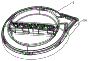
As shown in fig. 1, the backlight 2 includes a light emitting device 21, an optical panel 22, a double-sided tape 23, and a frame 24 for carrying the light emitting device 21 and the emblem 1. The light emitting assembly 21 is fixed to the bottom of the frame 24. The optical panel 22 is located above the light emitting assembly 21 and is mounted on top of the frame 24 by a double-sided adhesive 23. The emblem 1 is mounted above the frame 24.
As shown in fig. 2, the light emitting assembly 21 includes a light emitting element 211 and a PCB (printed circuit board) board 212. In this embodiment, the number of the light emitting elements 211 is plural. Each light emitting element 211 is SMT (surface mount) mounted on the PCB 212 in a desired light emitting area, and the SMT printed PCB 212 is fabricated into a light emitting assembly 21 (also a PCBA (printed circuit board assembly) board).
In this embodiment, each light emitting element 211 corresponds to an LED (light emitting diode) lamp 2111. The light source of the LED 2111 is one of white light, blue light, red light, or RGB (red, green, blue) seven-color light. That is, the LED 2111 may be used in a variety of colors to display different modes and function indications of the vehicle sign, which also enhances the brand value of the vehicle. In other embodiments, the light source of the LED light 2111 may also be other lights with desired colors, and may be designed according to different function indicators. In this embodiment, the LED 2111 may be selected to have high or medium power to meet the brightness requirements of the vehicle.
As shown in fig. 1 and 2, the front surface of the PCB 212 is provided with a plurality of first pads (not shown) and second pads (not shown) disposed away from the first pads. The second pad is located at a position not affecting the first pad. Each LED light 2111 is attached to a first pad. Specifically, one LED lamp 2111 is attached to one first pad.
As shown in fig. 2 and 8, in the present embodiment, the second pad is used for soldering the power supply line 3 or soldering the connecting socket (not shown). The connection socket is used to provide a power interface for the LED lamp 2111. The second pad is used for bonding the power supply line 3. As shown in fig. 2, the power supply line 3 is provided with a bonding pad (i.e., a second bonding pad) on the front surface of the PCB 212 according to an actual demand position. The power supply wire 3 is soldered after penetrating the reverse side of the PCB 212 to the front side of the PCB 212. And waterproof glue is coated on the back surface of the backlight source 2, namely on the back surface of the PCB 212, at the wire outlet position of the power supply wire 3, so that the waterproof function of the vehicle logo plate is enhanced. The power supply line 3 is connected with the existing 12V voltage of the automobile, and meanwhile, the LED lamp 2111 can adjust the brightness of the backlight source 2 by adjusting the control voltage. In this embodiment, the control voltage is adjusted by serially connecting current limiting resistors 4 at a position that does not affect the LED lamp 2111, and the number and positions of the current limiting resistors 4 are set according to the actual brightness requirement.
As shown in fig. 1 and 5, in the present embodiment, the optical panel 22 is milky white, and has a strong atomization effect. The optical panel 22 is a diffusion plate for optically diffusing the light emitted from the light emitting element 211. The diffuser plate has the main function of atomizing the light sources emitted by the LED lamps 2111, so that light spots are scattered and become uniform surface light sources. In other embodiments, the optical panel 22 may also be a panel such as a light guide plate. In this embodiment, the outer contour edge of the optical panel 22 is aligned in line with the outer contour edge of the emblem 1. The optical panel 22 is provided with a shielding layer 221 located directly above the light emitting element 211 to shield part of the light emitted by the light emitting element 211 from reflection.
In this embodiment, the following two preferred embodiments are provided for the specific implementation of the shielding layer 221.
In the first embodiment shown in fig. 6, the blocking layer 221 is formed by an optical ink micro-dot printing process, and is used to improve the stealthy speckle effect caused by insufficient haze of the optical panel 22, so that the final light emission is more uniform. In this embodiment, the micro-dots can be correspondingly adjusted according to the arrangement of the light emitting elements 211, so that the light source of the light emitting elements 211 can be refracted at multiple angles, and the light eyes can be blurred, so that the light emitting area is uniform in brightness.
In a second embodiment, as shown in fig. 7, where B in fig. 7 is the position of the optical panel 22 directly above the center of the LED lamp 2111. The shielding layer 221 is a plurality of shielding point combinations, each light emitting element 211 corresponds to one shielding point combination, and one shielding point combination is arranged from dense to sparse from the center of the corresponding light emitting element 211 to outward, so that a part of light directly above the light emitting element 211 can be shielded and reflected and is basically consistent with the optical brightness above the non-light emitting element 211. That is, the dots of the corresponding optical ink micro dots are dense right above each LED light 2111, so that strong light right above the LED light 2111 is shielded by the dense dots to reflect light to a certain degree; the light around each LED lamp 2111 is weaker than that in the middle, the corresponding micro-point dots are sparser, and the shielded light is less; the whole is distributed and arranged from dense to sparse to balance the whole brightness uniformity of the vehicle logo 1, and finally high brightness and high uniformity are realized. In other embodiments, the masking layer 221 can also be offset printing or other printing processes. In this example, the optical ink was white oil, insoluble in water, and had good oxygen resistance and chemical stability. In other embodiments, other optical inks such as protective oils may also be used.
In this embodiment, the frame 24 is a rubber frame support, which is acid-resistant and alkali-resistant, and improves reliability. In other embodiments, the frame 24 may also be an iron frame bracket or the like. In this embodiment, the frame 24 acts as a bridge to the overall structure of the light-emitting sign. The height of the frame 24 determines the number of the LED lamps 2111 and the final display effect, and the light emitting angle overlap of the LED lamps 2111 can be calculated according to the number distribution simulation of the LED lamps 2111 to obtain a height as short as possible, so as to reduce the overall thickness.
As shown in fig. 3 and 4, the frame 24 includes a horizontal portion 241 and a blocking wall portion 242 formed by vertically extending the horizontal portion 241. The horizontal portion 241 has a through hole 2411. In this embodiment, the number of the through holes 2411 corresponds to the number of the LED lamps 2111, and is also plural. The light emitting element 211 is exposed from the through hole 2411. In this embodiment, each through hole 2411 gradually increases along the bottom surface of the horizontal portion 241 toward the top surface, i.e., is in a bell (oblique) shape, so as to reflect and scatter the light emitted by the light emitting element 211, so that the brightness between two adjacent LED lamps 2111 can be better connected, and finally the brightness between two adjacent LED lamps 2111 is improved. The retaining wall portion 242 corresponds to the distribution shape of the light emitting elements 211, that is, the retaining wall portion 242 structure is designed to follow the shape of the required light emission of the emblem 1 so as to separate the position of the emblem 1 where the light emission is required from the position where the light emission is not required, which is beneficial to effectively collecting and utilizing the light energy of the light emitting elements 211 and prevents the light emitted by the light emitting elements 211 from all illuminating the emblem 1.
As shown in fig. 1, 5 and 7, the specific assembling steps of the luminescent car logo plate of the present embodiment are as follows:
the light emitting element 211 is first attached to the PCB 212. That is, each LED 2111 is correspondingly bonded to the first pad, and the light emitting assembly 21 is formed after the bonding.
The light emitting assembly 21 is then mounted on the bottom of the frame 24. The light emitting assembly 21 and the frame 24 may be fixed by a snap or a screw, or by a dispensing and sealing process, which is helpful for waterproof.
The optical panel 22 is then placed on top of the frame 24. The optical panel 22 is attached to the top of the frame 24 (i.e., the light-emitting surface of the light-emitting element 211) by a double-sided tape 23. Since the optical panel 22 is provided with the shielding layer 221, the backlight 2 with high brightness and high uniformity is completed.
And finally, installing the car logo 1 on the backlight source 2, and finally displaying the highlight uniformly. The mounting mode can be through the technology of sealed point gluing, or other buckles and screw modes, etc. Meanwhile, waterproof treatment needs to be done during installation.
In this embodiment, by providing the shielding layer 221 which is located directly above the light emitting element 211 to shield part of the light emitted from the light emitting element 211 in the optical panel 22, the backlight 2 with high luminance and high uniformity can be obtained. The car logo 1 is arranged on the backlight 2, so that the car logo has high brightness, high uniformity and high reliability, and finally, the high identification performance and the aesthetic feeling are brought to the car logo.
As shown in fig. 1 and 9, in the present embodiment, a light-emitting car logo is further provided, including a car logo 1 and the backlight 2, where the car logo 1 is installed on the upper surface of the backlight 2.
In this document, the terms "upper", "lower", "front", "rear", "left", "right", "top", "bottom", "inner", "outer", "vertical", "horizontal", and the like indicate orientations or positional relationships based on the orientations or positional relationships shown in the drawings, and are only for the purpose of clarity and convenience of description of the technical solutions, and thus, should not be construed as limiting the present invention.
As used herein, the terms "comprises," "comprising," or any other variation thereof, are intended to cover a non-exclusive inclusion, including not only those elements listed, but also other elements not expressly listed.
The above description is only for the specific embodiments of the present invention, but the scope of the present invention is not limited thereto, and any person skilled in the art can easily conceive of the changes or substitutions within the technical scope of the present invention, and all the changes or substitutions should be covered within the scope of the present invention. Therefore, the protection scope of the present invention shall be subject to the protection scope of the appended claims.
Claims (10)
1. The backlight source comprises a vehicle logo, and is characterized in that the upper surface of the backlight source is used for mounting the vehicle logo, the backlight source comprises a light-emitting component and an optical panel, the light-emitting component comprises a light-emitting element, the optical panel is positioned above the light-emitting component, and the optical panel is provided with a shielding layer which is positioned right above the light-emitting element and used for shielding and reflecting partial light rays emitted by the light-emitting element.
2. The backlight of claim 1, wherein the blocking layer is formed by an optical ink micro-dot printing process.
3. The backlight of claim 1, wherein the shielding layer is a plurality of shielding point combinations, the light-emitting assembly comprises a plurality of light-emitting elements, each light-emitting element corresponds to one of the shielding point combinations, and one of the shielding point combinations is arranged from a center to a center of the corresponding light-emitting element.
4. The backlight for a lighted vehicle sign according to claim 2, wherein the optical ink is white oil.
5. The backlight source for a luminescent car license plate of claim 1, wherein the light emitting component corresponds to a LED lamp, the light emitting component further comprises a PCB board, a plurality of first bonding pads and second bonding pads are disposed on a front surface of the PCB board, the second bonding pads are disposed far away from the first bonding pads, each of the LED lamps is attached to one of the first bonding pads, and the second bonding pads are used for welding a power supply line or a connecting seat.
6. The backlight for a lighted vehicle sign according to claim 1, wherein the optical panel is a diffuser plate for optically diffusing the light emitted by the light emitting elements.
7. The backlight of claim 1, further comprising a frame for carrying the light emitting assembly and the emblem, the light emitting assembly being secured to a bottom portion of the frame, the optical panel being mounted to a top portion of the frame, the emblem being mounted over the frame.
8. The backlight for a lighted emblem of claim 7, wherein the frame comprises a horizontal portion having through-holes that increase in size from a bottom surface to a top surface of the horizontal portion, the light emitting elements being exposed at the through-holes.
9. The backlight for a lighted sign according to claim 8, wherein said frame comprises a wall portion formed by vertical extension of said horizontal portion, said wall portion corresponding to the shape of said light emitting element.
10. A light-emitting emblem comprising an emblem and the backlight of any of claims 1-9, the emblem mounted on an upper surface of the backlight.
Priority Applications (1)
| Application Number | Priority Date | Filing Date | Title |
|---|---|---|---|
| CN202010461568.9A CN111554211A (en) | 2020-05-27 | 2020-05-27 | Backlight source of light-emitting vehicle sign and light-emitting vehicle sign |
Applications Claiming Priority (1)
| Application Number | Priority Date | Filing Date | Title |
|---|---|---|---|
| CN202010461568.9A CN111554211A (en) | 2020-05-27 | 2020-05-27 | Backlight source of light-emitting vehicle sign and light-emitting vehicle sign |
Publications (1)
| Publication Number | Publication Date |
|---|---|
| CN111554211A true CN111554211A (en) | 2020-08-18 |
Family
ID=72001681
Family Applications (1)
| Application Number | Title | Priority Date | Filing Date |
|---|---|---|---|
| CN202010461568.9A Pending CN111554211A (en) | 2020-05-27 | 2020-05-27 | Backlight source of light-emitting vehicle sign and light-emitting vehicle sign |
Country Status (1)
| Country | Link |
|---|---|
| CN (1) | CN111554211A (en) |
-
2020
- 2020-05-27 CN CN202010461568.9A patent/CN111554211A/en active Pending
Similar Documents
| Publication | Publication Date | Title |
|---|---|---|
| US7249869B2 (en) | Light emitting device | |
| US8258704B2 (en) | Vehicle lighting display system | |
| US9903999B2 (en) | Light assembly for illuminating an emblem | |
| JP3326338B2 (en) | Luminescent sign board | |
| CN111161651B (en) | Luminous label with light transmission function and manufacturing method thereof | |
| JP2004062139A (en) | Light guide | |
| CN109964078A (en) | Utilize the illumination component of light guiding film | |
| CN112485939A (en) | Integrated vehicle-mounted display with atmosphere lamp module | |
| CN213008011U (en) | Front grille through lamp device and front bumper assembly | |
| CN110481455B (en) | Luminous sign assembly | |
| CN211827998U (en) | Backlight source of light-emitting vehicle sign and light-emitting vehicle sign | |
| CN210291721U (en) | Automobile dynamic image projection lamp based on glass projection film | |
| CN111637421A (en) | Vacuum aluminum plating energy-saving type automobile luminous sign | |
| CN111554211A (en) | Backlight source of light-emitting vehicle sign and light-emitting vehicle sign | |
| CN211780563U (en) | Interior atmosphere lamp assembly and automotive interior with LED backlight | |
| JP2004301822A (en) | Lighting system for display for vehicle | |
| CN211943178U (en) | Luminous signboard and car | |
| JP3137551B2 (en) | Display device and display element unit | |
| CN211493837U (en) | Car logo lamp | |
| CN112634782A (en) | Sign light-emitting structure | |
| CN218287616U (en) | Car logo and vehicle | |
| CN216716077U (en) | Car light illumination structure, car light and vehicle | |
| CN214504884U (en) | Sign light-emitting structure | |
| CN2847019Y (en) | Vehicle lamp structure | |
| JP2006049385A (en) | Light-emitting device |
Legal Events
| Date | Code | Title | Description |
|---|---|---|---|
| PB01 | Publication | ||
| PB01 | Publication | ||
| SE01 | Entry into force of request for substantive examination | ||
| SE01 | Entry into force of request for substantive examination |