CN111495260A - Mixing stirring device is used in production of ZAF antirust material - Google Patents
Mixing stirring device is used in production of ZAF antirust material Download PDFInfo
- Publication number
- CN111495260A CN111495260A CN202010391482.3A CN202010391482A CN111495260A CN 111495260 A CN111495260 A CN 111495260A CN 202010391482 A CN202010391482 A CN 202010391482A CN 111495260 A CN111495260 A CN 111495260A
- Authority
- CN
- China
- Prior art keywords
- mixing
- box body
- side wall
- stirring
- motor
- Prior art date
- Legal status (The legal status is an assumption and is not a legal conclusion. Google has not performed a legal analysis and makes no representation as to the accuracy of the status listed.)
- Pending
Links
Images


Classifications
-
- B—PERFORMING OPERATIONS; TRANSPORTING
- B01—PHYSICAL OR CHEMICAL PROCESSES OR APPARATUS IN GENERAL
- B01F—MIXING, e.g. DISSOLVING, EMULSIFYING OR DISPERSING
- B01F33/00—Other mixers; Mixing plants; Combinations of mixers
- B01F33/80—Mixing plants; Combinations of mixers
- B01F33/82—Combinations of dissimilar mixers
- B01F33/821—Combinations of dissimilar mixers with consecutive receptacles
-
- B—PERFORMING OPERATIONS; TRANSPORTING
- B01—PHYSICAL OR CHEMICAL PROCESSES OR APPARATUS IN GENERAL
- B01F—MIXING, e.g. DISSOLVING, EMULSIFYING OR DISPERSING
- B01F35/00—Accessories for mixers; Auxiliary operations or auxiliary devices; Parts or details of general application
- B01F35/10—Maintenance of mixers
- B01F35/12—Maintenance of mixers using mechanical means
- B01F35/123—Maintenance of mixers using mechanical means using scrapers for cleaning mixers
-
- B—PERFORMING OPERATIONS; TRANSPORTING
- B01—PHYSICAL OR CHEMICAL PROCESSES OR APPARATUS IN GENERAL
- B01F—MIXING, e.g. DISSOLVING, EMULSIFYING OR DISPERSING
- B01F35/00—Accessories for mixers; Auxiliary operations or auxiliary devices; Parts or details of general application
- B01F35/40—Mounting or supporting mixing devices or receptacles; Clamping or holding arrangements therefor
- B01F35/43—Supporting receptacles on frames or stands
-
- B—PERFORMING OPERATIONS; TRANSPORTING
- B01—PHYSICAL OR CHEMICAL PROCESSES OR APPARATUS IN GENERAL
- B01F—MIXING, e.g. DISSOLVING, EMULSIFYING OR DISPERSING
- B01F35/00—Accessories for mixers; Auxiliary operations or auxiliary devices; Parts or details of general application
- B01F35/71—Feed mechanisms
- B01F35/716—Feed mechanisms characterised by the relative arrangement of the containers for feeding or mixing the components
- B01F35/7164—Feed mechanisms characterised by the relative arrangement of the containers for feeding or mixing the components the containers being placed in parallel before contacting the contents
-
- B—PERFORMING OPERATIONS; TRANSPORTING
- B01—PHYSICAL OR CHEMICAL PROCESSES OR APPARATUS IN GENERAL
- B01F—MIXING, e.g. DISSOLVING, EMULSIFYING OR DISPERSING
- B01F35/00—Accessories for mixers; Auxiliary operations or auxiliary devices; Parts or details of general application
- B01F35/71—Feed mechanisms
- B01F35/717—Feed mechanisms characterised by the means for feeding the components to the mixer
- B01F35/718—Feed mechanisms characterised by the means for feeding the components to the mixer using vacuum, under pressure in a closed receptacle or circuit system
Abstract
The invention discloses a mixing and stirring device for producing ZAF antirust materials, and relates to the technical field of antirust material production equipment; the four corners of the lower side wall of the box body are fixed with support legs, the lower side of one side wall of the box body is fixedly inserted with a discharge pipe, the outer end of the discharge pipe is inserted with a sealing plug, the center of the upper side wall of the box body is fixedly inserted with a feed pipe, and the lower end of the feed pipe passes through the upper side wall of the box body and is suspended at the upper side inside the box body; the mixing device also comprises a first mixing mechanism and a second mixing mechanism, wherein the first mixing mechanism is arranged on the upper side inside the box body, a mixing pool in the first mixing mechanism is suspended on the lower side of the feeding pipe, the second mixing mechanism is arranged on the lower side of the mixing pool, a second motor in the second mixing mechanism is fixed on the outer side wall of the rear side of the box body, and the second motor is connected with an external power supply; in the mixing process, the two different mixing mechanisms are used for mixing in sequence, so that the mixing effect is improved.
Description
Technical Field
The invention relates to the technical field of antirust material production equipment, in particular to a mixing and stirring device for producing ZAF antirust material.
Background
ZAF antirust material has solved the problem that current product easily bubbled, compare the antirust property more excellent with current product, the price/performance ratio is higher, at the in-process of preparation, add the talcum powder to the inside of ZAF antirust material and can improve the performance of ZAF antirust material, nevertheless ZAF antirust material and talcum powder are when mixing, mostly directly adopt the motor to drive the (mixing) shaft and rotate, the (mixing) shaft drives the stirring leaf and rotates and stir, the function singleness, and it is relatively poor to mix the effect, urgent to wait to improve.
Disclosure of Invention
The invention aims to provide a mixing and stirring device for producing ZAF antirust materials, which is reasonable in design and convenient to use, aiming at overcoming the defects and shortcomings of the prior art, and the mixing and stirring device is sequentially mixed through two different mixing mechanisms in the mixing process, so that the mixing effect is improved.
In order to achieve the purpose, the invention adopts the technical scheme that: the device comprises a box body, support legs, a feeding pipe, a discharging pipe and a sealing plug, wherein the support legs are fixed at four corners of the lower side wall of the box body, the discharging pipe is fixedly inserted into the lower side of one side wall of the box body, the sealing plug is inserted into the outer end of the discharging pipe, the feeding pipe is fixedly inserted into the center of the upper side wall of the box body, and the lower end of the feeding pipe passes through the upper side wall of the box body and is suspended on the upper side inside the box body; the mixing device also comprises a first mixing mechanism and a second mixing mechanism, wherein the first mixing mechanism is arranged on the upper side inside the box body, a mixing pool in the first mixing mechanism is suspended on the lower side of the feeding pipe, the second mixing mechanism is arranged on the lower side of the mixing pool, a second motor in the second mixing mechanism is fixed on the outer side wall of the rear side of the box body, and the second motor is connected with an external power supply;
the first mixing mechanism also comprises a spring, a rack, a half gear, a rotating rod, a slide rail, a slide block and a first motor, wherein the mixing tank is suspended at the upper side inside the box body, a plurality of round holes are equiangularly arranged on the outer periphery of the lower side wall of the mixing tank, the slide block is fixed on the outer side walls of the front side and the rear side of the mixing tank, the slide rail is respectively arranged inside the slide block in a sliding manner, the slide rails of the front side and the rear side are respectively fixed on the inner side walls of the front side and the rear side of the box body, the first motor is fixed on the rear side wall of the box body and connected with an external power supply, the rotating rod is fixed on the output shaft of the first motor, the front end of the rotating rod sequentially penetrates through the rear side wall of the box body and the two half gears and is in screwed connection with the front side wall of the box body through a bearing, the racks of the upper sides, the other end of the spring is fixed on the inner side wall of one side of the box body;
above-mentioned mixing mechanism No. two still contains the (mixing) shaft, the connecting rod, stirring board and deflector, the rear end of (mixing) shaft and the output shaft fixed connection of No. two motors, after the front end of (mixing) shaft passed the sealed bearing in the lateral wall behind the box, insert and establish in the sealed bearing who fixes in the lateral wall before the box, impartial angle is fixed with the several connecting rod on the front and back both sides of (mixing) shaft outer lateral wall, the other end of two connecting rods on the same straight line is fixed respectively on the stirring board, the stirring board is trapezoidal setting, the downside contact of stirring board is provided with the deflector, one side of this deflector sets up in the downside of discharging pipe one end, the other side of deflector inclines backward, fix.
Further, the both sides of box all be equipped with vacuum powder conveyer, vacuum powder conveyer's discharge gate hangs and establishes the upside at the inlet pipe, pours rust-resistant material and talcum powder respectively to the vacuum powder conveyer of both sides in, conveys the feeding via vacuum powder conveyer.
Further, mix the fixed protection casing in center of lateral wall under the pond, be equipped with No. three motors in this protection casing, No. three motors are connected with external power supply, be fixed with the pivot on the output shaft of No. three motors, the upper end of pivot is passed and is mixed the interior bearing of lateral wall under the pond, hang the inside of establishing at the mixed pond, the equiangular is fixed with several stirring leaf on the outer rampart of pivot, the stirring leaf hangs the inside of establishing at the mixed pond, after antirust material and talcum powder poured into the mixed pond in, start No. three motors, No. three motors drive the pivot and rotate, the pivot drives the stirring leaf and rotates, mix antirust material and talcum powder through the stirring leaf.
Furthermore, the outer side of one side wall of the stirring plate is fixed with a scraping plate, the outer side of the scraping plate and the lower side of the stirring plate are arranged on the same plane, and the antirust material and the talcum powder are turned upwards through the scraping plate.
Further, the upside of a box lateral wall be equipped with a body, one side of the door body connects through the hinge soon with the rear side of a box lateral wall, one side of the door body is connected through the front side of cross lock with a box lateral wall, the door body sets up in one side of mixing the pond, when needs clear up mixing the pond, opens a body, starts a motor for half wheel and rack separation will mix the pond and stimulate to the outside again, will mix the pond and take off until will mixing the pond, clear up.
Further, the lateral wall of mixing pond one side on the contact have the push pedal, the equidistance is fixed with a plurality of inserted bars on one side wall of push pedal, the outside activity cover of this inserted bar is equipped with the sleeve pipe, the sleeve pipe is inserted and is established in the spring, the sheathed tube other end is fixed on the inside wall of box one side.
The working principle of the invention is as follows: when the mixing tank is used, the antirust material and the talcum powder are poured into the feeding pipe respectively, and then fall into the mixing tank through the feeding pipe, then the first motor is started, the first motor drives the rotating rod to rotate, the rotating rod drives the half gears on the front side and the rear side to rotate, the tooth side of the half gears drives the rack to move towards one side, the rack drives the mixing tank to move, the mixing tank compresses the spring, when the smooth edge of the half gears moves to the upper side, the rack is loosened, the mixing tank is pushed to the initial position due to the elasticity of the spring, the antirust material and the talcum powder are driven to shake back and forth in the back and forth movement process of the mixing tank, the mixing effect is further achieved, the antirust material and the talcum powder fall onto the guide plate through the round hole in the mixing process, the second motor is started again, the stirring shaft is driven to rotate by the second motor, the stirring shaft drives the stirring plate to rotate, and in the, after mixing, convey to the discharging tube in via the deflector again, pull out the sealing plug after, carry out the ejection of compact.
After adopting the structure, the invention has the beneficial effects that:
1. in the mixing process, the materials are sequentially mixed by two different mixing mechanisms, so that the mixing effect is improved;
2. when the half gear is rotated, the rack can be driven to move to one side, when the smooth edge of the half gear rotates to the upper side, the rack is loosened, the mixing tank is pushed to the initial position through the spring, the antirust material and the talcum powder are mixed and filtered in the process of moving back and forth, the filtering effect is achieved while the mixing effect is achieved, and impurities in the antirust material and the talcum powder are retained on the upper side of the mixing tank;
3. the rust-resistant material and the talcum powder that mix via the mixing tank fall to the deflector on, then mix via the stirring board again for rust-resistant material and talcum powder roll from top to bottom, and then increased the effect of mixing.
Drawings
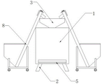
FIG. 1 is a schematic structural diagram of the present invention.
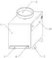
Fig. 2 is a schematic structural diagram of the box body in the invention.
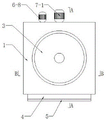
FIG. 3 is a top view of the housing of the present invention.
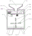
Fig. 4 is a sectional view taken along line a-a of fig. 3.
Fig. 5 is a sectional view taken along line B-B in fig. 3.
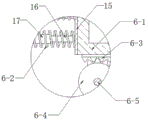
Fig. 6 is an enlarged view of the portion C in fig. 5.
FIG. 7 is a schematic view of the structure of the mixing tank of the present invention.
FIG. 8 is a schematic view of the structure of the stirring plate and scraper in the present invention.
Description of reference numerals:
the device comprises a box body 1, support legs 2, a feeding pipe 3, a discharging pipe 4, a sealing plug 5, a first mixing mechanism 6, a mixing pool 6-1, a spring 6-2, a rack 6-3, a half gear 6-4, a rotating rod 6-5, a sliding rail 6-6, a sliding block 6-7, a first motor 6-8, a round hole 6-9, a second mixing mechanism 7, a second motor 7-1, a stirring shaft 7-2, a connecting rod 7-3, a stirring plate 7-4, a guide plate 7-5, a vacuum powder conveyor 8, a protective cover 9, a third motor 10, a rotating shaft 11, a stirring blade 12, a scraping plate 13, a door body 14, a pushing plate 15, an inserted rod 16 and a sleeve 17.
The specific implementation mode is as follows:
the technical solutions in the embodiments of the present invention will be clearly and completely described below with reference to the drawings in the embodiments of the present invention, and it is obvious that the described embodiments are only a part of the embodiments of the present invention, and not all of the embodiments. All other embodiments, which can be derived by a person skilled in the art from the embodiments given herein without making any creative effort, shall fall within the protection scope of the present invention.
As shown in fig. 1 to 8, the following technical solutions are adopted in the present embodiment: the automatic feeding device comprises a box body 1, support legs 2, a feeding pipe 3, a discharging pipe 4 and a sealing plug 5, wherein the support legs 2 are fixedly welded at four corners of the lower side wall of the box body 1, the discharging pipe 4 is fixedly welded at the lower side of one side wall of the box body 1 in an inserting manner, the sealing plug 5 is inserted into the outer end of the discharging pipe 4, the feeding pipe 3 is fixedly welded at the center of the upper side wall of the box body 1 in an inserting manner, the lower end of the feeding pipe 3 passes through the upper side wall of the box body 1 and then is hung at the upper side inside the box body 1, vacuum powder conveyors 8 are arranged at two sides of the box body 1, and a discharging port of each; the mixing device also comprises a first mixing mechanism 6 and a second mixing mechanism 7, the upper side inside the box body 1 is provided with the first mixing mechanism 6, a mixing pool 6-1 in the first mixing mechanism 6 is arranged at the lower side of the feeding pipe 3 in a hanging manner, the first mixing mechanism 6 also comprises a spring 6-2, a rack 6-3, a half gear 6-4, a rotating rod 6-5, a sliding rail 6-6, a sliding block 6-7 and a first motor 6-8, the mixing pool 6-1 is arranged at the upper side inside the box body 1 in a hanging manner, a protective cover 9 is welded and fixed at the center of the lower side wall of the mixing pool 6-1, a third motor 10 is arranged in the protective cover 9, the third motor 10 is connected with an external power supply, the model of the third motor 10 is 40KTYZ, a rotating shaft 11 is fixed on an output shaft of the third motor 10 through a bolt, the upper end of the rotating shaft 11 passes through a bearing in the lower, the bearing is suspended in the mixing tank 6-1, the outer ring of the bearing is welded and fixed with the inner side wall at the lower side of the mixing tank 6-1, the inner ring of the bearing is welded and fixed with the lower end of a rotating shaft 11, four stirring blades 12 are welded and fixed on the outer ring wall of the rotating shaft 11 at equal angles, the stirring blades 12 are suspended in the mixing tank 6-1, the antirust material and the talcum powder are stirred through the stirring blades 12, the mixing effect is improved, a plurality of round holes 6-9 are formed in the periphery of the lower side wall of the mixing tank 6-1 at equal angles, sliding blocks 6-7 are welded and fixed on the outer side walls at the front side and the rear side of the mixing tank 6-1, sliding rails 6-6 are respectively arranged in the sliding blocks 6-7 in the sliding mode, the sliding rails 6-6 at the front side and the rear side are respectively fixed on the inner side walls at the front side and, the first motor 6-8 is connected with an external power supply, the first motor 6-8 is 50KTYZ in type, a rotating rod 6-5 is fixed on an output shaft of the first motor 6-8 through a bolt, the front end of the rotating rod 6-5 sequentially penetrates through the rear side wall of the box body 1 and two half gears 6-4 and is in screwed connection with the front side wall of the box body 1 through a bearing, the bearing is embedded in the front side wall of the box body 1, the outer ring of the bearing is fixedly welded with the inner side wall of the front side of the box body 1, the inner ring of the bearing is fixedly welded with the front end of the rotating rod 6-5, the half gears 6-4 are respectively fixedly welded with the front end and the rear end of the rotating rod 6-5, racks 6-3 are respectively meshed with the upper sides of the half gears 6-4, the racks 6-3 on the front side and the rear side are respectively fixed on the front side and the rear side of the lower side wall of the mixing pool 6-1 through, the left end of the spring 6-2 is welded and fixed on the inner side wall of one side of the box body 1, the upper side of the right side wall of the box body 1 is provided with a door body 14, the rear side of the door body 14 is connected with the rear side of the right side wall of the box body 1 in a rotating mode through a hinge, the front side of the door body 14 is connected with the front side of the right side wall of the box body 1 through a cross lock, the door body 14 is arranged on the right side of the mixing pool 6-1 and can conveniently take out the mixing pool 6-1 for cleaning, the outer side wall of the left side of the mixing pool 6-1 is contacted with a push plate 15, a plurality of inserting rods 16 are welded and fixed on the left side wall of the push plate 15 at equal intervals, the outer sides of the inserting rods 16 are movably sleeved with sleeve pipes 17, the sleeve pipes 17;
a second mixing mechanism 7 is arranged on the lower side of the mixing pool 6-1, a second motor 7-1 in the second mixing mechanism 7 is fixed on the outer side wall of the rear side of the box body 1 through bolts, the second motor 7-1 is connected with an external power supply, and the model of the second motor 7-1 is 60 KTYZ; the second mixing mechanism 7 also comprises a stirring shaft 7-2, a connecting rod 7-3, a stirring plate 7-4 and a guide plate 7-5, the rear end of the stirring shaft 7-2 is fixedly connected with the output shaft of the second motor 7-1 through a bolt, the front end of the stirring shaft 7-2 passes through a sealing bearing in the rear side wall of the box body 1 and is inserted and fixed in the sealing bearing in the front side wall of the box body 1, the outer rings of the sealing bearings at the front side and the rear side are respectively welded and fixed with the inner side walls of the front side wall and the rear side wall of the box body 1, the inner ring of the sealing bearing is welded and fixed with the stirring shaft 7-2, a plurality of connecting rods 7-3 are welded and fixed at equal angles on the front side and the rear side of the outer ring wall of the stirring shaft 7-2, the other ends of the, the lower side of the stirring plate 7-4 is provided with a guide plate 7-5 in a contact manner, the front side of the guide plate 7-5 is arranged at the lower side of the inner end of the discharge pipe 4, the rear side of the guide plate 7-5 inclines upwards and is fixed on the inner side wall of the box body 1 in a welding manner, the outer side of one side wall of the stirring plate 7-4 is fixedly provided with a scraping plate 13 in a welding manner, and the outer side of the scraping plate 13 and the side edge of the stirring plate 7-4 are arranged in the same plane, so that the stirring effect of the stirring plate 7-.
The working principle of the specific embodiment is as follows: when the device is used, the antirust material and the talcum powder are respectively poured into the vacuum powder conveyors 8 on the left side and the right side, the vacuum powder conveyors 8 are started to convey the antirust material and the talcum powder into the feeding pipes 3, then the antirust material and the talcum powder fall into the mixing tank 6-1 through the feeding pipes 3, then the first motor 6-8 and the third motor 10 are started, the third motor 10 drives the rotating shaft 11 to rotate, the rotating shaft 11 drives the stirring blades 12 to rotate, the stirring blades 12 mix the antirust material and the talcum powder in the mixing tank 6-1, the first motor 6-8 drives the rotating rod 6-5 to rotate, the rotating rod 6-5 drives the half gears 6-4 on the front side and the rear side to rotate, the tooth edges of the half gears 6-4 drive the rack 6-3 to move towards one side, the rack 6-3 drives the mixing tank 6-1 to move, and the mixing tank 6-1 compresses the spring 6-2 through the, when the smooth edge of the half gear 6-4 moves to the upper side, the rack 6-3 is loosened, the mixing pool 6-1 is pushed to the initial position due to the elastic force of the spring 6-2, the antirust material and the talcum powder are driven to shake back and forth in the process that the mixing pool 6-1 moves back and forth, and then the mixing effect is achieved, the antirust material and the talcum powder fall onto the guide plate 7-5 through the round hole 6-9 in the mixing process, the second motor 7-1 is started, the second motor 7-1 drives the stirring shaft 7-2 to rotate, the stirring shaft 7-2 drives the stirring plate 7-4 to rotate, the stirring plate 7-4 drives the scraping plate 13 to rotate, the antirust material and the talcum powder are driven to roll up and down in the rotating process, so that the antirust material and the talcum powder are fully mixed, and after the mixing is finished, the antirust material and the talcum powder are conveyed, after the sealing plug 5 is pulled out, discharging is carried out, when the mixing tank 6-1 needs to be cleaned, the door body 14 is opened, the mixing tank 6-1 is moved outwards and then taken down, cleaning is carried out, and later-stage use is facilitated.
After adopting above-mentioned structure, this embodiment's beneficial effect is as follows:
1. in the mixing process, the materials are sequentially mixed by two different mixing mechanisms, so that the mixing effect is improved;
2. when the half gear 6-4 is rotated, the rack 6-3 can be driven to move to one side, when the smooth edge of the half gear 6-4 rotates to the upper side, the rack 6-3 is loosened, the mixing tank 6-1 is pushed to the initial position through the spring 6-2, the antirust material and the talcum powder are mixed and filtered in the process of moving back and forth, the filtering effect is achieved while the mixing effect is achieved, and impurities in the antirust material and the talcum powder are retained on the upper side of the mixing tank 6-1;
3. the antirust material and the talcum powder mixed by the mixing tank 6-1 fall onto the guide plate 7-5, and are mixed by the stirring plate 7-4, so that the antirust material and the talcum powder roll up and down, and the mixing effect is further improved;
4. the left side and the right side of the box body 1 are respectively provided with a vacuum powder conveyor 8, so that the antirust material can be poured into the vacuum powder conveyor 8 on the left side, the talcum powder is poured into the vacuum powder conveyor 8 on the right side, and finally the talcum powder is conveyed into the feeding pipe 3, so that the feeding is convenient;
5. mix 6-1's inside and be equipped with stirring leaf 12, start No. three motor 10, No. three motor 10 drives stirring leaf 12 through pivot 11 and rotates, stirs rust-resistant material and talcum powder through stirring leaf 12, has promoted the effect of mixing.
Although the present invention has been described in detail with reference to the foregoing embodiments, it will be apparent to those skilled in the art that various changes in the embodiments and/or modifications of the invention can be made, and equivalents and modifications of some features of the invention can be made without departing from the spirit and scope of the invention.
Claims (7)
1. A mixing and stirring device for ZAF antirust material production comprises a box body (1), support legs (2), a feeding pipe (3), a discharging pipe (4) and a sealing plug (5), wherein the support legs (2) are fixed at four corners of the lower side wall of the box body (1), the discharging pipe (4) is inserted and fixed at the lower side of one side wall of the box body (1), the sealing plug (5) is inserted and arranged in the outer end of the discharging pipe (4), the feeding pipe (3) is inserted and fixed at the center of the upper side wall of the box body (1), and the lower end of the feeding pipe (3) is suspended at the upper side inside the box body (1) after penetrating through the upper side wall of the box body (1; the method is characterized in that: the mixing device also comprises a first mixing mechanism (6) and a second mixing mechanism (7), wherein the first mixing mechanism (6) is arranged on the upper side inside the box body (1), a mixing pool (6-1) in the first mixing mechanism (6) is suspended on the lower side of the feeding pipe (3), the second mixing mechanism (7) is arranged on the lower side of the mixing pool (6-1), a second motor (7-1) in the second mixing mechanism (7) is fixed on the outer side wall of the rear side of the box body (1), and the second motor (7-1) is connected with an external power supply;
the first mixing mechanism (6) further comprises a spring (6-2), a rack (6-3), a half gear (6-4), a rotating rod (6-5), a sliding rail (6-6), a sliding block (6-7) and a first motor (6-8), the mixing tank (6-1) is suspended at the upper side of the interior of the box body (1), a plurality of round holes (6-9) are formed in the outer periphery of the lower side wall of the mixing tank (6-1) in an equiangular mode, the sliding blocks (6-7) are fixed on the outer side walls of the front side and the rear side of the mixing tank (6-1), the sliding rails (6-6) are respectively arranged in the interior of the sliding block (6-7) in a sliding mode, the sliding rails (6-6) of the front side and the rear side are respectively fixed on the inner side walls of the front side and the rear side of the box body (1), the, the first motor (6-8) is connected with an external power supply, a rotating rod (6-5) is fixed on an output shaft of the first motor (6-8), the front end of the rotating rod (6-5) sequentially penetrates through the rear side wall of the box body (1) and two half gears (6-4) and then is in screwed connection with the front side wall of the box body (1) through a bearing, racks (6-3) are meshed with the upper sides of the half gears (6-4), the racks (6-3) on the front side and the rear side are respectively fixed on the front side and the rear side of the lower side wall of the mixing pool (6-1), a plurality of springs (6-2) are abutted to one side of the mixing pool (6-1), and the other ends of the springs (6-2) are fixed on the inner side wall of one side of the box body (1;
the second mixing mechanism (7) also comprises a stirring shaft (7-2), connecting rods (7-3), a stirring plate (7-4) and a guide plate (7-5), the rear end of the stirring shaft (7-2) is fixedly connected with the output shaft of the second motor (7-1), the front end of the stirring shaft (7-2) penetrates through a sealing bearing in the rear side wall of the box body (1) and is inserted and fixed in the sealing bearing in the front side wall of the box body (1), a plurality of connecting rods (7-3) are fixed on the front side and the rear side of the outer ring wall of the stirring shaft (7-2) at equal angles, the other ends of the two connecting rods (7-3) on the same straight line are respectively fixed on the stirring plate (7-4), the stirring plate (7-4) is arranged in a trapezoid shape, the lower side of the stirring plate (7-4) is provided with the guide plate (7-, one side of the guide plate (7-5) is arranged at the lower side of one end of the discharge pipe (4), and the other side of the guide plate (7-5) is fixed on the inner side wall of the box body (1) after inclining upwards.
2. The mixing and stirring device for ZAF antirust material production according to claim 1, characterized in that: the both sides of box (1) all be equipped with vacuum powder conveyer (8), the discharge gate of vacuum powder conveyer (8) hangs and establishes the upside at inlet pipe (3), falls antirust material and talcum powder respectively to the vacuum powder conveyer (8) of both sides in, conveys the feeding via vacuum powder conveyer (8).
3. The mixing and stirring device for ZAF antirust material production according to claim 1, characterized in that: a protective cover (9) is fixed at the center of the lower side wall of the mixing pool (6-1), a third motor (10) is arranged in the protective cover (9), the third motor (10) is connected with an external power supply, a rotating shaft (11) is fixed on an output shaft of the third motor (10), after the upper end of the rotating shaft (11) passes through a bearing in the lower side wall of the mixing pool (6-1), is suspended in the mixing tank (6-1), a plurality of stirring vanes (12) are fixed on the outer ring wall of the rotating shaft (11) at equal angles, the stirring vanes (12) are suspended in the mixing tank (6-1), after the antirust material and the talcum powder are poured into the mixing tank (6-1), the third motor (10) is started, the third motor (10) drives the rotating shaft (11) to rotate, the rotating shaft (11) drives the stirring blade (12) to rotate, and the antirust material and the talcum powder are mixed through the stirring blade (12).
4. The mixing and stirring device for ZAF antirust material production according to claim 1, characterized in that: and the outer sides of one side wall of the stirring plate (7-4) are respectively fixed with a scraper (13), the outer sides of the scrapers (13) and the lower side edge of the stirring plate (7-4) are arranged in the same plane, and the antirust material and the talcum powder are turned upwards through the scrapers (13).
5. The mixing and stirring device for ZAF antirust material production according to claim 1, characterized in that: the upper side of one side wall of the box body (1) is provided with a door body (14), one side of the door body (14) is connected with the rear side of one side wall of the box body (1) in a screwing mode through a hinge, one side of the door body (14) is connected with the front side of one side wall of the box body (1) through a cross lock, the door body (14) is arranged on one side of the mixing pool (6-1), when the mixing pool (6-1) needs to be cleaned, the door body (14) is opened, a first motor (6-8) is started, the half gear (6-4) is separated from the rack (6-3), and then the mixing pool (6-1) is pulled outwards until the mixing pool (6-1) is taken down for cleaning.
6. The mixing and stirring device for ZAF antirust material production according to claim 1, characterized in that: the outer side wall of one side of the mixing pool (6-1) is contacted with a push plate (15), a plurality of insert rods (16) are fixed on one side wall of the push plate (15) at equal intervals, a sleeve (17) is movably sleeved on the outer side of each insert rod (16), the sleeve (17) is inserted into the spring (6-2), and the other end of the sleeve (17) is fixed on the inner side wall of one side of the box body (1).
7. The mixing and stirring device for ZAF antirust material production according to claim 1, characterized in that: the working principle is as follows: when the device is used, the antirust material and the talcum powder are poured into the feeding pipe (3) respectively, then fall into the mixing tank (6-1) through the feeding pipe (3), then the first motor (6-8) is started, the first motor (6-8) drives the rotating rod (6-5) to rotate, the rotating rod (6-5) drives the half gears (6-4) on the front side and the rear side to rotate, the toothed edges of the half gears (6-4) drive the racks (6-3) to move towards one side, the racks (6-3) drive the mixing tank (6-1) to move, the mixing tank (6-1) compresses the spring (6-2), when the smooth edges of the half gears (6-4) move to the upper side, the racks (6-3) are loosened, and the mixing tank (6-1) is pushed to the initial position due to the elasticity of the spring (6-2), in the process of moving the mixing tank (6-1) back and forth, the antirust material and the talcum powder are driven to shake back and forth, and a mixing effect is achieved, the antirust material and the talcum powder fall onto the guide plate (7-5) through the round hole (6-9) in the mixing process, the second motor (7-1) is started again, the second motor (7-1) drives the stirring shaft (7-2) to rotate, the stirring shaft (7-2) drives the stirring plate (7-4) to rotate, in the rotating process, the antirust material and the talcum powder are driven to roll up and down, so that the antirust material and the talcum powder are fully mixed, after the mixing is completed, the antirust material and the talcum powder are conveyed into the discharging pipe (4) through the guide plate (7-5), and after the sealing plug (5) is pulled out.
Priority Applications (1)
| Application Number | Priority Date | Filing Date | Title |
|---|---|---|---|
| CN202010391482.3A CN111495260A (en) | 2020-05-11 | 2020-05-11 | Mixing stirring device is used in production of ZAF antirust material |
Applications Claiming Priority (1)
| Application Number | Priority Date | Filing Date | Title |
|---|---|---|---|
| CN202010391482.3A CN111495260A (en) | 2020-05-11 | 2020-05-11 | Mixing stirring device is used in production of ZAF antirust material |
Publications (1)
| Publication Number | Publication Date |
|---|---|
| CN111495260A true CN111495260A (en) | 2020-08-07 |
Family
ID=71878428
Family Applications (1)
| Application Number | Title | Priority Date | Filing Date |
|---|---|---|---|
| CN202010391482.3A Pending CN111495260A (en) | 2020-05-11 | 2020-05-11 | Mixing stirring device is used in production of ZAF antirust material |
Country Status (1)
| Country | Link |
|---|---|
| CN (1) | CN111495260A (en) |
Cited By (3)
| Publication number | Priority date | Publication date | Assignee | Title |
|---|---|---|---|---|
| CN112090340A (en) * | 2020-08-13 | 2020-12-18 | 安徽天安生物科技股份有限公司 | High-efficient machine that mixes is used in animal remedy production |
| CN112895200A (en) * | 2021-01-15 | 2021-06-04 | 方龙 | Plastic refuse pelletization equipment among domestic waste |
| CN113276346A (en) * | 2021-07-21 | 2021-08-20 | 昌亚新材料科技有限公司 | Centralized feeding machine and feeding method for feeding of multiple injection molding machines |
-
2020
- 2020-05-11 CN CN202010391482.3A patent/CN111495260A/en active Pending
Cited By (4)
| Publication number | Priority date | Publication date | Assignee | Title |
|---|---|---|---|---|
| CN112090340A (en) * | 2020-08-13 | 2020-12-18 | 安徽天安生物科技股份有限公司 | High-efficient machine that mixes is used in animal remedy production |
| CN112090340B (en) * | 2020-08-13 | 2023-11-24 | 安徽天安生物科技股份有限公司 | Animal remedy production is with high-efficient mixer |
| CN112895200A (en) * | 2021-01-15 | 2021-06-04 | 方龙 | Plastic refuse pelletization equipment among domestic waste |
| CN113276346A (en) * | 2021-07-21 | 2021-08-20 | 昌亚新材料科技有限公司 | Centralized feeding machine and feeding method for feeding of multiple injection molding machines |
Similar Documents
| Publication | Publication Date | Title |
|---|---|---|
| CN111495260A (en) | Mixing stirring device is used in production of ZAF antirust material | |
| CN210332347U (en) | Soil treatment agent mixing arrangement | |
| CN112454669B (en) | Rotary concrete pouring equipment | |
| CN109912069B (en) | Urban domestic wastewater treatment device | |
| CN212396610U (en) | Mixing stirring device is used in production of ZAF antirust material | |
| CN215311695U (en) | Efficient processingequipment for building material | |
| CN112093943A (en) | A processing apparatus for radioactive waste water | |
| CN208449609U (en) | A kind of concentrated feed production exclusion device | |
| CN215278877U (en) | High-efficient washing cauldron | |
| CN215538604U (en) | Extraction device is used in ethyl formate production | |
| CN111375231B (en) | Sludge scraping device of treatment tank for sewage treatment of environmental protection equipment | |
| CN114534305A (en) | Full-automatic tea coarse filtration refining equipment in tea fine and further processing | |
| CN113262536A (en) | Energy-concerving and environment-protective water based paint intelligence manufacturing installation | |
| CN216366959U (en) | Can improve branch of filter effect and wash and dry by fire all-in-one filtration | |
| CN220071612U (en) | Medical intermediate reaction kettle | |
| CN218393221U (en) | A mix preparation facilities for disappearance mould coating | |
| CN213913766U (en) | A agitating unit for reation kettle | |
| CN213977888U (en) | A recovery processing device for deplating agent | |
| CN216369228U (en) | Wet concrete separating and recovering equipment | |
| CN216935733U (en) | Mixer for food production | |
| CN220149251U (en) | Industrial wastewater treatment device | |
| CN216862711U (en) | Intelligent food additive processing material loading machine | |
| CN219150002U (en) | Blendor with conveying mechanism | |
| CN209865822U (en) | Salt water preparation device | |
| CN212731879U (en) | Stirring dosing unit of solid beverage production usefulness |
Legal Events
| Date | Code | Title | Description |
|---|---|---|---|
| PB01 | Publication | ||
| PB01 | Publication | ||
| SE01 | Entry into force of request for substantive examination | ||
| SE01 | Entry into force of request for substantive examination |