CN111467613B - Piston for an injection cartridge with a sealing structure of a specific dimensional ratio - Google Patents
Piston for an injection cartridge with a sealing structure of a specific dimensional ratio Download PDFInfo
- Publication number
- CN111467613B CN111467613B CN202010305601.9A CN202010305601A CN111467613B CN 111467613 B CN111467613 B CN 111467613B CN 202010305601 A CN202010305601 A CN 202010305601A CN 111467613 B CN111467613 B CN 111467613B
- Authority
- CN
- China
- Prior art keywords
- piston
- syringe
- barrel
- sealing element
- plunger
- Prior art date
- Legal status (The legal status is an assumption and is not a legal conclusion. Google has not performed a legal analysis and makes no representation as to the accuracy of the status listed.)
- Active
Links
Images


Classifications
-
- A—HUMAN NECESSITIES
- A61—MEDICAL OR VETERINARY SCIENCE; HYGIENE
- A61M—DEVICES FOR INTRODUCING MEDIA INTO, OR ONTO, THE BODY; DEVICES FOR TRANSDUCING BODY MEDIA OR FOR TAKING MEDIA FROM THE BODY; DEVICES FOR PRODUCING OR ENDING SLEEP OR STUPOR
- A61M5/00—Devices for bringing media into the body in a subcutaneous, intra-vascular or intramuscular way; Accessories therefor, e.g. filling or cleaning devices, arm-rests
- A61M5/178—Syringes
- A61M5/31—Details
- A61M5/32—Needles; Details of needles pertaining to their connection with syringe or hub; Accessories for bringing the needle into, or holding the needle on, the body; Devices for protection of needles
- A61M5/3202—Devices for protection of the needle before use, e.g. caps
-
- A—HUMAN NECESSITIES
- A61—MEDICAL OR VETERINARY SCIENCE; HYGIENE
- A61M—DEVICES FOR INTRODUCING MEDIA INTO, OR ONTO, THE BODY; DEVICES FOR TRANSDUCING BODY MEDIA OR FOR TAKING MEDIA FROM THE BODY; DEVICES FOR PRODUCING OR ENDING SLEEP OR STUPOR
- A61M5/00—Devices for bringing media into the body in a subcutaneous, intra-vascular or intramuscular way; Accessories therefor, e.g. filling or cleaning devices, arm-rests
- A61M5/178—Syringes
- A61M5/31—Details
- A61M5/315—Pistons; Piston-rods; Guiding, blocking or restricting the movement of the rod or piston; Appliances on the rod for facilitating dosing ; Dosing mechanisms
- A61M5/31511—Piston or piston-rod constructions, e.g. connection of piston with piston-rod
- A61M5/31513—Piston constructions to improve sealing or sliding
-
- A—HUMAN NECESSITIES
- A61—MEDICAL OR VETERINARY SCIENCE; HYGIENE
- A61M—DEVICES FOR INTRODUCING MEDIA INTO, OR ONTO, THE BODY; DEVICES FOR TRANSDUCING BODY MEDIA OR FOR TAKING MEDIA FROM THE BODY; DEVICES FOR PRODUCING OR ENDING SLEEP OR STUPOR
- A61M5/00—Devices for bringing media into the body in a subcutaneous, intra-vascular or intramuscular way; Accessories therefor, e.g. filling or cleaning devices, arm-rests
- A61M5/178—Syringes
- A61M5/31—Details
- A61M5/315—Pistons; Piston-rods; Guiding, blocking or restricting the movement of the rod or piston; Appliances on the rod for facilitating dosing ; Dosing mechanisms
- A61M5/31511—Piston or piston-rod constructions, e.g. connection of piston with piston-rod
- A61M5/31515—Connection of piston with piston rod
-
- A—HUMAN NECESSITIES
- A61—MEDICAL OR VETERINARY SCIENCE; HYGIENE
- A61M—DEVICES FOR INTRODUCING MEDIA INTO, OR ONTO, THE BODY; DEVICES FOR TRANSDUCING BODY MEDIA OR FOR TAKING MEDIA FROM THE BODY; DEVICES FOR PRODUCING OR ENDING SLEEP OR STUPOR
- A61M5/00—Devices for bringing media into the body in a subcutaneous, intra-vascular or intramuscular way; Accessories therefor, e.g. filling or cleaning devices, arm-rests
- A61M5/50—Devices for bringing media into the body in a subcutaneous, intra-vascular or intramuscular way; Accessories therefor, e.g. filling or cleaning devices, arm-rests having means for preventing re-use, or for indicating if defective, used, tampered with or unsterile
- A61M5/5013—Means for blocking the piston or the fluid passageway to prevent illegal refilling of a syringe
- A61M5/502—Means for blocking the piston or the fluid passageway to prevent illegal refilling of a syringe for blocking the piston
-
- A—HUMAN NECESSITIES
- A61—MEDICAL OR VETERINARY SCIENCE; HYGIENE
- A61M—DEVICES FOR INTRODUCING MEDIA INTO, OR ONTO, THE BODY; DEVICES FOR TRANSDUCING BODY MEDIA OR FOR TAKING MEDIA FROM THE BODY; DEVICES FOR PRODUCING OR ENDING SLEEP OR STUPOR
- A61M5/00—Devices for bringing media into the body in a subcutaneous, intra-vascular or intramuscular way; Accessories therefor, e.g. filling or cleaning devices, arm-rests
- A61M5/178—Syringes
- A61M5/31—Details
- A61M2005/3103—Leak prevention means for distal end of syringes, i.e. syringe end for mounting a needle
- A61M2005/3107—Leak prevention means for distal end of syringes, i.e. syringe end for mounting a needle for needles
- A61M2005/3109—Caps sealing the needle bore by use of, e.g. air-hardening adhesive, elastomer or epoxy resin
Abstract
The present invention relates to a piston with sealing structure of specific dimensional proportions for a syringe and to a piston for use in an injector comprising a cylinder having a longitudinal axis and an inner wall, the piston having a deformable sealing element with a convex surface which abuts the inner wall of the cylinder at an abutment interface and seals an annular gap between said inner wall of said cylinder and said piston when the piston is inserted in the cylinder, the abutment interface and the deformable sealing element having axial dimensions parallel to the longitudinal axis, characterized in that: the ratio between the axial dimension of the abutment interface and the axial dimension of the deformable sealing element is in the range between 0.01 and 0.2. In other aspects, the invention relates to an injector comprising a plunger, and to the use of a plunger in a disposable syringe. The plunger may prevent refilling of the syringe.
Description
The present application is a divisional application of the application entitled "piston with seal structure of specific dimensional ratio for syringe" filed as 2014, 6/4, 2014, 201480032306.3.
Technical Field
The present invention relates to a plunger for use in a syringe comprising a barrel together with the plunger, the plunger having a deformable sealing element with a convex surface which abuts an inner wall of the barrel at an abutment interface and seals an annular gap between the plunger and the inner wall of the barrel. The invention also relates to a syringe and a plunger rod for use in the syringe. The syringe of the present invention is suitable for the delivery of pharmaceutical ingredients such as vaccines.
Background
The known disposable syringe is in many cases constructed such that it can be reused, although it is intended for a single use only. One can refill the syringe barrel by pulling on a conventional plunger which, through its connection to the piston, refills the cylindrical barrel for a second injection. The construction of the cartridge without any measures against re-use is generally simpler, since it does not require such additional measures. In many cases, the possibility of reusing disposable syringes is not a concern. However, in particularly poor developing countries, due to the lack of necessary medical equipment, it has become common to reuse disposable injection cartridges, which are only insufficiently cleaned and sterilized due to insufficient hygienic conditions.
Examples of disposable cartridges are provided in US5,795,337, WO 2004/078243, WO 2004/075958, WO 2004/033018, US4,252,118, US5,158,549 and WO 2002/32485. Further examples of syringes are provided in US4,430,082, EP 0047442, FR1600637 and US 3,545,607.
However, there are certain areas within the syringe where the user will go to great lengths to manipulate the disposable syringe for reuse. With regard to vaccination activities in poor third world countries it is fairly normal to apply pressure through the needle, which is usually generated manually by using a larger standard syringe, which is refilled with vaccine for a second injection through a glass vial.
Furthermore, undesirable reuse is quite common among drug addicts, where one or more persons use the same syringe and needle without hesitation, without first being sterilized.
Throughout the world, whether in hospitals, clinics or at vaccination sites, such repeated use of disposable syringes often results in human infection with life-threatening diseases, as well as blood-borne, infectious diseases such as AIDS and hepatitis b, among others.
Recognizing these problems, the World Health Organization (WHO) has utilized and encouraged the use of self-destructive (AD) syringes that are not likely to be reusable for different structural reasons.
Such AD-syringes tend to be expensive to manufacture and thus expensive to use, and to the extent necessary, many countries do not have the ability to purchase these types of disposable syringes.
There are many different AD-syringes used in connection with vaccination activities in the poorest countries of the world. In addition to containing personal auto-disable technology, which most often requires additional components, some are also configured to resist pressure filling, thereby preventing various attempts to reuse the syringe, as compared to normal or conventional syringes.
From PCT/EP00/00028 is known an AD-injector which operates by separating the piston and plunger during the emptying of the syringe, since the piston is sequentially turned approximately 90 degrees during the emptying process and thus away from its interconnection with the plunger. The piston is then positioned at the bottom of the barrel and held there. The sealing surface of the piston has a significant vertical extension on the longitudinal axis of the tub. The vertical extension of the abutment surfaces of the piston makes the friction relatively low, whether the piston is moving or not. Due to the large vertical abutment surface of the piston, the lubrication that is essential for utilizing the syringe barrel, whether the piston is moving or stationary, will be effective between the piston and the barrel inner wall. This approach is problematic in order to resist pressure filling, since the friction necessary to resist pressure filling may not be achieved when lubrication is permanently present at the abutting interface between the piston and the inner wall of the barrel.
As with the pistons mentioned in the above mentioned patent applications, the pistons known from conventional and AD-syringes are provided with one or more sealing surfaces to ensure tightness between the piston and the inside wall of the barrel, which is relatively permissive, and which means that these pistons, when mounted in barrels having a diameter smaller than the outside diameter of the piston, cause the abutment surface of the sealing surface to expand significantly in the vertical direction and thus in the longitudinal axis of the barrel. The permanent presence of lubrication in the area between the plunger and the inner wall of the barrel means that with a given pressure through the needle one can press the plunger and thereby position it to the starting position, whereby one will be able to reuse the syringe for a new injection.
Other AD-syringes are provided with a metal clip or one-way valve that effectively shuts off the pressure filling through the needle. The known AD-syringe thus avoids pressure filling on its own due to the presence of the additional component.
This is because the piston in AD-syringes is mainly unchanged compared to the pistons in conventional syringes and, therefore, cannot resist refilling of the syringe itself against pressure, which is a legal requirement of AD-syringes that WHO wishes to utilize.
There are many challenges to manufacturing and assembling the AD-syringe described above. First, it is desirable to manufacture syringes having as few parts as possible to ensure a low manufacturing price and thus a wide market in third world countries. Furthermore, the syringe should include provisions for preventing reuse by periodic filling or pressure filling of the syringe. For example, a syringe having a detachable connection between the piston and the plunger would not prevent reuse by pressure filling. Furthermore, the aforementioned solution of preventing re-use is not suitable for implementation in other types of AD-syringes, resulting in various different solutions, none of which are interoperable. Finally, AD-syringes should provide convenient usability.
Disclosure of Invention
In view of the above, it is an object of the invention to provide a syringe of the kind mentioned in the opening paragraph which has a simple structure, is disposable and easy to handle, is inexpensive to manufacture and is not reusable.
The present application provides the following:
1) A plunger for use in a syringe, the syringe comprising a barrel having a longitudinal axis and an inner wall, the plunger having a deformable sealing element with a convex surface that, upon insertion of the plunger into the barrel, abuts the inner wall of the barrel at an abutment interface and seals an annular gap between the inner wall of the barrel and the plunger, the abutment interface and the deformable sealing element having axial dimensions parallel to the longitudinal axis, characterized in that: the ratio between the axial dimension of the abutment interface and the axial dimension of the deformable sealing element is in the range between 0.01 and 0.2.
2) The piston of claim 1), wherein the piston is solid and has two or more deformable sealing elements as defined in 1.
3) The piston of any of 1) or 2), wherein the piston does not include any pigment or dye.
4) The piston of any of claims 1) to 3), wherein the piston and the deformable sealing element are of the same material.
5) The piston of any of claims 1) to 4), wherein the deformable sealing element, or the deformable sealing element and the piston, has a Shore A hardness in the range of about 50 to about 90.
6) The piston according to any one of 1) to 5), wherein the piston is made by injection molding.
7) The piston of claim 6), wherein the piston is made of a styrenic block copolymer.
8) A syringe comprising a piston according to any one of 1) to 7).
9) A syringe comprising a barrel having a longitudinal axis and an inner wall and a plunger having a deformable sealing element with a convex surface that abuts the inner wall of the barrel at an abutment interface and seals an annular gap between the inner wall of the barrel and the plunger, the abutment interface and the deformable sealing element having axial dimensions parallel to the longitudinal axis, characterized in that: the ratio between the axial dimension of the abutment interface and the axial dimension of the deformable sealing element is in the range between 0.01 and 0.2.
10 The syringe of any of claims 8) or 9), wherein initial movement of the plunger requires a pressure of at least about 300kPa.
11 The syringe of any of claims 8) to 10), wherein the inner wall of the barrel comprises a lubricant, such as silicone oil or a vaccine or pharmaceutical composition.
12 The syringe of any one of claims 8) to 11), wherein the barrel has an inner diameter of up to 45mm, such as a diameter in the range from about 2mm to about 10 mm.
13 The syringe of any of claims 8) to 12), wherein, on one side transverse to a plane of the barrel, through the abutment interface, the convex surface of the deformable sealing element and the inner wall of the barrel define a first contact angle in the range of from about 0 ° to about 50 °, and on the other side of the plane, the convex surface of the deformable sealing element and the inner wall of the barrel define a second contact angle in the range of from about 0 ° to about 50 °.
14 The syringe of any one of claims 8) to 13), wherein the barrel is pre-filled with a pharmaceutical composition.
15 Use of a piston according to any of 1) to 7) in a disposable syringe.
16 Use of a plunger with a deformable sealing element with a convex surface in a disposable cartridge, which deformable sealing element, when mounted in said cartridge, abuts an inner wall of said cartridge at an abutment interface and seals an annular gap between said inner wall of said cartridge and said plunger, said abutment interface and said deformable sealing element having an axial dimension parallel to a longitudinal axis of said cartridge, characterized in that: the ratio between the axial dimension of the abutment interface and the axial dimension of the deformable sealing element is in the range between 0.01 and 0.2.
17 A piston rod for a syringe according to any one of claims 8) to 14), the syringe comprising a hypodermic needle attached to an outlet at an outlet end of the barrel opposite to the driving end of the barrel, the barrel having an operating length defined by the distance from the driving end of the barrel to the outlet end of the barrel minus the dimension of the piston parallel to the longitudinal axis, the piston rod having a tubular section for accommodating the hypodermic needle, the tubular section having a needle insertion end and a needle protection end opposite to the needle insertion end, the needle insertion end comprising engagement means for engaging complementary engagement means of the outlet or the hypodermic needle, the tubular section comprising means for driving the piston, characterized in that: the length of the tubular section is equal to or greater than the operative length of the barrel.
18 17), wherein the means for driving the piston is located at the needle insertion end or the needle protection end.
19 The piston rod according to any of 17) or 18), wherein the means for driving the piston has a concave surface or shape complementary to a convex driving surface of the piston.
20 The piston rod according to any one of 17) to 19), wherein a ratio of an outer diameter of the tubular section to an inner diameter of the cylinder is in a range of 50% to 90%.
21 The piston rod according to any of 17) to 20), wherein the piston rod comprises one or more guiding structures on an outer side surface of the tubular section for axially guiding the piston rod when inserted into the barrel of the syringe.
22 The piston rod according to any of 17) to 21), wherein the tubular section of the piston rod comprises an elastic material for sealing the hypodermic needle.
23 The piston rod according to any one of 17) to 22), wherein the piston comprises a thumb plate at the needle insertion end or at the needle protection end.
24 23), wherein the piston rod has a length equal to the operating length of the barrel, and wherein the thumb plate has a cross-sectional area equal to or less than an inner cross-sectional area of a barrel of the syringe.
25 The piston rod of 23), wherein the thumb plate has a cross-sectional area that is greater than the cross-sectional area of the barrel.
26 A syringe comprising a barrel having a longitudinal axis and an inner wall, a plunger having a deformable sealing element abutting the inner wall of the barrel at an abutment interface and sealing an annular gap between the inner wall of the barrel and the plunger, and a piston rod having a tubular section for accommodating the hypodermic needle, the tubular section having a needle insertion end and a needle protection end opposite the needle insertion end, the needle insertion end comprising engagement means for engaging complementary engagement means of the outlet or the hypodermic needle, the tubular section comprising means for driving the plunger, wherein the length of the tubular section is greater than the operational length of the barrel, and wherein the tubular section comprises a resilient material for sealing the hypodermic needle.
27 A kit of parts comprising a hypodermic needle and a piston rod according to any one of 16) to 25).
This object is met in relation to a first aspect of the invention by providing a plunger for use in a syringe comprising a barrel having a longitudinal axis and an inner wall, the plunger having a deformable sealing element with a convex surface abutting the inner wall of the barrel at an abutment interface and sealing an annular gap between the inner wall of the barrel and the plunger when the plunger is inserted in the barrel, the abutment interface and the deformable sealing element having axial dimensions parallel to the longitudinal axis, characterized in that: the ratio between the axial dimension of the abutment interface and the axial dimension of the deformable sealing element is in the range between 0.01 and 0.2. In another aspect, the present invention relates to a syringe comprising a plunger. In a further aspect, the invention relates to an injector comprising a barrel having a longitudinal axis and an inner wall, and a plunger having a deformable sealing element with a convex surface that abuts the inner wall of the barrel at an abutment interface and seals an annular gap between the inner wall of the barrel and the plunger, the abutment interface and the deformable sealing element having axial dimensions parallel to the longitudinal axis, characterized in that: the ratio between the axial dimension of the abutment interface and the axial dimension of the deformable sealing element is in the range between 0.01 and 0.2. In a further aspect, the invention meets the object by providing a plunger in a disposable cartridge having a deformable sealing element with a convex surface, the deformable sealing element abutting an inner wall of the cartridge at an abutment interface when mounted in the cartridge and sealing an annular gap between the inner wall of the cartridge and the plunger, the abutment interface and the deformable sealing element having an axial dimension parallel to the longitudinal axis of the cartridge, wherein the ratio between the axial dimension of the abutment interface and the axial dimension of the deformable sealing element is in the range between 0.01 and 0.2. In a particular embodiment, the present invention relates to the use of any embodiment of the plunger of the present invention in a disposable syringe.
Where the deformable sealing element abuts the inner wall of the barrel, the interface between the deformable sealing element and the inner wall will provide both static and dynamic friction. Movement of the piston in the barrel will require the application of a force sufficient to overcome the initial static friction and subsequent dynamic friction; the static friction will be greater than the dynamic friction and thus the force providing the initial movement of the piston will be greater than the force required to provide continued movement of the piston. Once the piston stops moving, the force providing the initial movement must again be overcome. The inventors have now surprisingly found that when the ratio between the axial dimension of the abutment interface and the axial dimension of the deformable sealing element is in the range between 0.01 and 0.4 (e.g. between 0.01 and 0.2, between 0.01 and 0.15, between 0.01 and 0.1, between 0.01 and 0.05, etc.), the piston via the deformable sealing element will provide a force, such as a static friction, on the inner wall of the barrel which prevents movement of the piston in the barrel within the range of forces normally available when attempting to refill a syringe using a manual device, such as another syringe. In general, the inner wall of the barrel needs to be lubricated in order to keep the dynamic friction low enough to ensure sufficient sliding of the piston and to allow the piston to move easily in the barrel and thereby deliver the medicament during injection. Without being bound by theory, the inventors believe that for certain combinations of the design of the deformable sealing element (i.e. when the piston according to the invention is inserted into the barrel) and the choice of lubricant, the deformable sealing element pushes the lubricant away from the inner wall surface of the barrel to create direct contact between the deformable sealing element and the inner wall, requiring a pressure of, for example, 300kPa to create an initial movement, for example an axial initial movement, of the piston in the barrel. This is particularly relevant when the ratio between the axial dimension of the abutment interface and the axial dimension of the deformable sealing element is small, such as in the range between 0.01 and 0.1, for example between 0.01 and 0.05, and further even more relevant when the viscosity of the lubricant, for example a silicone oil lubricant, is also low, such as in the range between 500cSt and 2000cSt, such as about 1000 cSt. In general, the smaller the ratio between the axial dimension of the abutment interface and the axial dimension of the deformable sealing element, the greater the force exerted on the inner wall via the deformable sealing element, and thus the greater the static friction between the inner wall and the deformable sealing element, for example at the abutment interface; the inventors have found that a range between 0.01 and 0.4 is relevant for the diameter of syringes conventionally used for delivering pharmaceutical compositions, for example having an internal diameter of between about 2mm and about 10mm, although the internal diameter is not limited and will typically be up to 45mm, such as in the range of 0.1mm to 45 mm. The inner diameter may be, for example, about 10mm, e.g., about 20mm, about 30mm, about 40mm, etc. In particular, since the axial dimension of the abutment interface is smaller than the axial dimension of the deformable sealing element, the force exerted by the piston on the inner wall is concentrated (i.e. at the abutment interface) and will thus maximize the friction generated between the deformable sealing element and the inner wall. Preferably, the ratio between the axial dimension of the abutment interface and the axial dimension of the deformable sealing element is in the range between 0.01 and 0.2, for example between 0.01 and 0.1, such as between 0.01 and 0.05. In general, these parameters may be selected to control the pressure required for initial movement of the piston, and in other embodiments the required pressure is 250kPa, 200kPa, 150kPa, or 100kPa.
The injector may be any kind of injector used to deliver a pharmaceutical composition to a subject through the skin of the subject. For example, the injector may be a syringe fitted with a hypodermic needle to inject the pharmaceutical composition, e.g. via Subcutaneous (SC), intramuscular (IM) or Intravenous (IV) delivery or another type of delivery, or the injector may be a needle-free injector (NFI) capable of providing a narrow high-speed fluid jet that penetrates the skin and delivers the pharmaceutical composition to the subject, e.g. via SC or IM delivery. The syringe may also take the form of a cartridge or vial.
The syringe includes a barrel. In the context of the present invention, a "cylinder" is any kind of tube or similar allowing the piston to move from one position to another in the cylinder. The cylinder will typically have a "drive end" and an "outlet end" opposite one another. The driving end of the cylinder allows it to be moved in the cylinder close to the piston, i.e. to "drive" the piston. Likewise, the piston has a drive surface facing the drive end of the cylinder and an outlet surface opposite the drive surface facing the outlet end of the cylinder. In general, the distance from the drive end of the cylinder to the outlet end of the cylinder minus the dimension of the piston parallel to the longitudinal axis of the cylinder defines the "operating length" of the cylinder. The piston may be moved from the drive end towards the outlet end using any means, for example the piston may be moved towards the outlet end using a piston rod, a plunger or fluid pressure (e.g. gas or liquid pressure). It is particularly preferred that the piston is not movable, for example from the outlet end towards the drive end, by engagement of the piston with, for example, a piston rod or the like from the drive end. In a certain embodiment, the syringe does not comprise a plunger rod. In another embodiment, the syringe comprises a plunger rod.
The piston has a piston body and a deformable sealing element that abuts the inner wall of the cylinder at an abutment interface and seals an annular gap between the piston and the inner wall of the cylinder. The term "abutment interface" refers to any section of the inner wall and the deformable sealing element that are in contact with each other, and does not impose any limitation on the inner wall of the barrel or the surface of the sealing element. Thus, the piston will delimit the outlet section of the cylinder of the piston (i.e. at the outlet surface of the piston) and the drive section of the cylinder (i.e. at the drive surface of the piston) and prevent fluid communication from the outlet section to the drive section (or vice versa) through the piston. The movement of the piston in the cylinder towards the outlet end will thereby eject fluid present in the outlet section, e.g. via the outlet. The piston body does not abut against the inner wall of the cylinder and only the sealing element present on the piston body abuts against the inner wall of the cylinder. As defined above, the piston may have one or more deformable sealing elements, although the piston may also have further sealing elements having other shapes and functions. For example, the piston may have a supporting sealing element capable of guiding or controlling the orientation of the piston in the cylinder.
In a preferred embodiment, the piston has two or more deformable sealing elements and the piston is solid, i.e. it has no cavity or the like. The solid piston with two or more deformable sealing elements may be symmetrical with respect to the transverse plane such that its orientation when inserted into the barrel is irrelevant. In contrast, an asymmetric piston (e.g. a piston having a cavity, such as a cavity for receiving a piston rod) needs to be oriented before insertion into the barrel, e.g. such that the piston can be driven by the piston rod inserted into the cavity. The need to remove the orienting piston greatly simplifies the production of syringes (e.g., pre-filled syringes) and thereby reduces production costs. Preferably, the solid piston does not comprise any means of engaging the piston rod. This embodiment is particularly advantageous when used with the piston rod of the present invention. For example, a solid piston without a mechanism for engaging the piston rod only allows the piston to be pushed through the piston rod, thereby emptying the cylinder.
The deformable sealing element and the abutment interface have an axial dimension, i.e. a dimension parallel to the longitudinal axis of the cylinder. The axial dimension of the deformable sealing element may also be referred to as the "height" of the deformable sealing element, and typically the axial dimension of the deformable sealing element is the largest axial dimension of the deformable sealing element. Likewise, the abutment interface also has an axial dimension, which may be referred to as the "height" of the abutment interface. Accordingly, the drive end of the cylinder may be referred to as the upper end of the cylinder or syringe and the outlet end may be referred to as the lower end.
In an embodiment of the invention, the initial movement of the piston requires a pressure of at least about 300kPa. The initial movement may be in the axial direction of the barrel of the syringe. In particular, for a syringe having an inner diameter of about 4.65mm, the required pressure of 300kPa is considered sufficient to prevent refilling of the syringe through the outlet using a manually operated syringe attached to the outlet. In other embodiments, the pressure is at least 350kPa, at least 400kPa, at least 450kPa, or at least 500kPa. A minimum pressure of 300kPa to produce an initial movement, such as an axial initial movement, is particularly advantageous for pre-filled syringes that do not need to be accurately filled by an end user, whereas syringes that are not pre-filled may need to be accurately filled by an end user.
In an embodiment of the invention, the inner wall of the barrel comprises a lubricant. By selecting parameters such as viscosity, e.g. kinematic viscosity, and the amount of lubricant applied, the dynamic friction between the inner wall of the barrel and the deformable sealing element is reduced or adjusted to a desired degree. Medical grade silicone oil is the current industry standard for use as a syringe lubricant, but any suitable medical grade lubricant, such as glycerin, may be used that does not deleteriously interact with the drug component (e.g., drug medium). The lubricant, for example, can have a kinematic viscosity in a range of about 100cSt to about 15,000cSt, such as about 500cSt to about 10,000cSt or about 1,000cSt to about 8,000cSt. The lubricant may be applied to the inner wall of the barrel using any means as desired. For example, the lubricant may be sprayed on the inside wall of the barrel, such as by spraying it down onto and into the inside wall of the barrel, resulting in all or part of the inside surface of the barrel being coated with the lubricant. When the barrel is made of a heat resistant material (e.g., glass, metal, or some polymer), the lubricant may be applied using a bake application technique. This technique generally involves the application of a lubricant (e.g., silicone oil as an emulsion) which is then baked onto the surface of the drum at a particular temperature and for a particular length of time. The lubricant may also be applied using vapor deposition.
It is also possible that all or part of the piston surface (e.g. the surface of the deformable sealing element) may be coated with a lubricant. The lubricant on the piston surface may be of the same type as the lubricant used on the barrel. The surface of the piston and the inner wall of the barrel may include a lubricant, or a lubricant may be applied to the surface of the piston or the inner wall of the barrel. In certain embodiments, a pharmaceutical composition (e.g., a vaccine or drug) for injection via a syringe is used as a lubricant. For example, the pharmaceutical composition may provide the only lubricant in the syringe and no other lubricant need be used. In particular, the pharmaceutical composition may comprise excipients, for example excipients that provide a lubricating effect in the syringe, among other functions. When the pharmaceutical composition provides a lubricating effect, the piston surface and/or the inner wall of the barrel may not require any additional lubricant, although it is also possible to use additional lubricant if desired.
The inventors have observed that the effect of the deformable sealing element on the inner wall of the cylinder is more pronounced when the contact angle between the surface of the deformable sealing element and the inner wall of the cylinder is in the range of about 10 ° to about 30 °, and more pronounced when the deformable sealing element is convex. Further, the effect is still more pronounced when the deformable sealing element or piston and the deformable sealing element have a Shore a hardness (Shore a hardness) in the range of about 70 to about 90, for example about 70 to about 80.
When the deformable sealing element pushes the lubricant away to create direct contact between the deformable sealing element and the inner wall of the cylinder, the effect will be a high static friction for the initial movement of the piston, e.g. a pressure of at least 300kPa is required for the movement of the piston, but once this static friction has been overcome, the piston (i.e. the deformable sealing element) will be lubricated and the dynamic friction will be low to allow the piston to move easily. When the movement of the piston stops, the high static friction must be overcome again. This is particularly advantageous for disposable syringes which are intended not to be refilled via the syringe or the outlet.
It is also possible that the surface of the inner wall of the barrel and/or the surface of the piston (e.g. the deformable sealing element and optionally the supporting sealing element, or the piston and sealing element) are chemically functionalized to provide a smooth surface without the need for additional lubrication, for example from a lubricant. For example, these surfaces may be functionalized with perfluoro groups (perfluor groups).
The piston includes a deformable sealing element. In the context of the present invention, the term "deformable" describes that the deformable sealing element can be deformed and thus seal the annular gap between the inner wall of the cylinder and the piston. Thus, the deformable sealing element will have a size in a relaxed state (e.g. in a state without deformation such as deformation caused by insertion of the plunger into the barrel) and the diameter (e.g. of the plunger including the deformable sealing element) will be larger than the inner diameter of the barrel of the syringe in the relaxed state. This ensures that the deformable sealing element will seal the annular gap between the inner wall of the cylinder and the piston. The diameter of the deformable sealing element is typically 3% to 20%, for example 5% to 15% larger than the inner diameter of the barrel.
The deformable sealing element is made of a material of suitable hardness and elasticity to ensure that the annular gap between the inner wall of the cylinder and the piston is sealed. Any such material may be selected for the deformable sealing element. In a preferred embodiment, the piston of the present invention is made from a suitable thermoplastic polymer by injection molding. Any thermoplastic elastomer may be used. Suitable thermoplastic polymers include Styrene Block Copolymers (SBC) such as hydrogenated-H-SBC- (SEBS-styrene-ethylene-butylene-styrene or the like) or non-hydrogenated (SBS-styrene-butadiene-styrene) or alloys of these and other compatible polymers. Preferred SBCs are those sold by AlphaGary corporation (Leominster, MA, USA) under the known trade mark Evoprene. In brochures "EVOPRENE TM Evoprene, and preferably Evoprene, is described in Thermoplastic Elastomer (TPE) Compounds-GENERAL INFORMATION (published by AlphaGary, 7 months 2007) TM The polymer is Evoprene TM Super G、Evoprene TM G、Evoprene TM GC and Evoprene TM HP in the brochure "EVOPRENE" respectively TM SUPER G Thermoplastic Elastomer(TPE)Compounds”、“EVOPRENE TM G Thermoplastic Elastomer(TPE)Compounds”、“EVOPRENE TM GC Thermoplastic Elastomer (TPE) Compounds "and" EVOPRENE TM HP Thermoplastic Elastomer (TPE) Compounds "(published by AlphaGary, 7.2007). The contents of all mentioned pamphlets of AlphaGary are incorporated herein by reference. When the piston is injection molded, the piston can be made with lower tolerances provided by techniques such as vulcanization, which is commonly used in the manufacture of conventional rubber pistons.Suitable materials include elastomers, such as rubbers, e.g. natural rubber, synthetic rubber (polyisoprene rubber, butyl rubber), silicone rubber and the like, which may be defined, for example, with respect to the shore durometer, which indicates the elasticity of the elastic material and measures the hardness of the elastic material, wherein the higher the durometer, the harder the compound. For example, in embodiments of the invention, the deformable sealing element or piston and the deformable sealing element have a shore a hardness in the range of about 50 to about 90 (preferably 60 to 80, more preferably 71 to 76). The terms "shore hardness" and "shore durometer" are used interchangeably. In general, the deformable sealing element will be homogeneous and comprise the same material throughout the entire volume of the deformable sealing element, the material having a shore a hardness in the given range. By using a material having a shore a hardness in the above range, a relatively hard elastic material is provided. This enables the piston to exert sufficient force against the inner wall of the barrel and thereby provide static friction to resist substantial pressure, e.g. 300kPa, when the piston is exposed to pressure filling, e.g. by a hypodermic needle. It should be noted that the shore a durometer is only one of many ways to characterize the material properties of the selected material, and that other tests may be used to characterize the material.
The piston may be made of any material. In particular, the piston body does not contact the inner wall of the barrel, and the material of the piston body generally only needs to be inert with respect to any pharmaceutical composition in the syringe. The deformable sealing element should likewise be inert with respect to the pharmaceutical composition in the syringe. In certain embodiments of the invention, the piston and the deformable sealing element are of the same material, e.g., the piston body and the deformable sealing element are of the same material. By providing the piston (e.g. piston body) and the deformable sealing element and any optional supporting sealing element with the same material, a more cost-effective and simple production is possible, thereby largely avoiding different process steps, such as time-consuming assembly.
In one embodiment of the invention, the piston is dyed or colored, e.g., the piston is black, to provide contrast between the piston and the barrel of the syringe. This contrast will allow for more accurate dosing when the cartridge includes a volume reading. For example, in a cartridge marked with black lines indicating volume, a black plunger may make readings easier to read in order to better control the volume aspired into or ejected from the syringe. However, pigments and dyes may be filtered from the plunger into the pharmaceutical composition in the syringe. This is particularly relevant for syringes pre-filled with a pharmaceutical composition, since in this case the pharmaceutical composition may be in contact with the piston for a prolonged period of time. In a preferred embodiment, the piston of the present invention does not include any pigments or dyes, e.g., the piston is "clear". This is particularly preferred when the piston is used in a syringe comprising a pharmaceutical composition, since it neither risks leakage of dye or pigment nor expresses the need for a contrast agent, since filling of the syringe is performed by an automatic filling device.
The surface of the deformable sealing element may have any shape desired. In a certain embodiment, the deformable sealing element has a convex surface, although the surface is not limited to a convex shape. In this context, the term "convex" means that a straight line between any two points within the deformable sealing element does not cross the surface of the deformable sealing element. When the deformable sealing element has a convex surface, the force exerted on the inner wall of the cylinder via the deformable sealing element will be maximized, since the deformation of the deformable sealing element in the direction of the longitudinal axis of the cylinder is minimized. The convexity is particularly advantageous when the ratio between the axial dimension of the abutment interface and the axial dimension of the deformable sealing element is in the range between 0.01 and 0.2, for example between 0.01 and 0.1 or between 0.01 and 0.05, and in general the smaller the ratio between the axial dimension of the abutment interface and the axial dimension of the deformable sealing element, the more pronounced the effect of the convex surface is, because the more concentrated the force exerted by the deformable sealing element on the inner wall of the cylinder.
The interface between the inner wall of the barrel and the deformable sealing element will define a contact angle, for example a contact angle in a direction parallel to the longitudinal axis of the barrel. Typically, the contact angle between the surface of the deformable sealing element and the inner wall of the barrel is in the range of about 0 ° to about 50 °. Specifically, on one side transverse to the plane of the cylinder, the convex surface of the deformable sealing element and the inner wall of the cylinder define, by the abutment interface, a first contact angle in the range from about 0 ° to about 50 °, and on the other side of the plane, the convex surface of the deformable sealing element and the inner wall of the cylinder define a second contact angle in the range from about 0 ° to about 50 °. The preferred range of contact angle is from about 10 ° to about 30 °. When these contact angles are below 50 °, the force exerted on the inner wall of the cylinder via the deformable sealing element is maximized, so that the static friction will also be maximized. Furthermore, when the contact angle is below 50 °, the deformable sealing element is prevented from tilting. In the context of the present invention, the term "tilt" refers to the situation in which the deformable sealing element deforms in substantially opposite directions upon application of a force in the direction of the longitudinal axis of the barrel. The tilting of the deformable sealing element may result in reduced static friction, allowing the piston to move more easily towards either end of the cylinder. Tilting is also generally minimized when the piston comprises two or more deformable sealing elements. Thus, a slanted deformable sealing element may not be suitable for AD-syringes. Tilting can also create a risk that the volume of liquid expelled from the barrel is difficult to control.
The barrel can be made of any relevant material, and typical materials include polymeric materials such as Cyclic Olefin Copolymers (COC), for example TOPAS Polymers (available from TOPAS Advanced Polymers, inc.), or polystyrene, or glass. COC polymers are preferred due to their excellent barrier properties and thereby accommodate the need for long term storage of the medicament. It is also contemplated that the barrel may be made of metal, or it may comprise any combination of polymeric materials, glass, or metals. The cross-sectional shape of the barrel is not limited, although it is preferred that the barrel have a circular cross-section. It is also contemplated that the cross-section may be oval, elliptical, polygonal, etc. When the barrel has a circular cross-section, the diameter (e.g., inner diameter) may have any value conventionally used for syringes. For example, in preferred embodiments, the inner diameter of the barrel is in the range of about 2mm to about 10mm, such as 4.65mm or 8.80mm.
Throughout the entire barrel cross-section, the barrel may be opened at the drive end of the barrel, which allows removal and insertion of the plunger, and thereby also filling of the syringe via the drive end. The barrel may also have a ridge or protrusion or the like at the drive end which prevents the piston from being removed once inserted into the barrel. In particular, the ridge or protrusion may provide a "locking means" of a "snap lock means", wherein a complementary "spring means" is comprised on the piston rod. After moving the piston to the outlet end of the cylinder, a spring lock device or the like may lock the piston rod, thereby preventing refilling of the cylinder.
When the syringe is a syringe, the barrel may comprise a fitting, for example at the outlet end, adapted to fit a hypodermic needle. Thus, the barrel may have, for example, a (e.g. tapered) end section with an outlet (e.g. a tubular outlet) from the barrel, which outlet provides or comprises engagement means for engaging complementary engagement means of the hypodermic needle, e.g. the engagement means and the complementary engagement means may comprise a male-female interaction, wherein the tubular outlet optionally comprises an external thread, e.g. a helical external thread, and the hypodermic needle optionally comprises a complementary internal thread, e.g. a helical internal thread. The hypodermic needle may be mounted to allow for easy removal and replacement of the hypodermic needle, or the hypodermic needle may be permanently mounted on the syringe. In particular, the hypodermic needle may be mounted on the syringe such that its removal requires destruction of the syringe, thereby preventing reuse, for example by mounting a new hypodermic needle, and also limiting refilling of the syringe from the outlet end via the hypodermic needle, which is cumbersome and inefficient. When the injector is an NFI, the outlet tube may be sufficiently narrow to provide an outlet flow of sufficient velocity to penetrate the skin of the subject. The outlet tube of the NFI may be designed to engage with a closure member; the same engagement means used with a syringe with a hypodermic needle is associated with the closure member and NFI.
In an embodiment of the invention, the preferred pre-filled syringe is a syringe with a hypodermic needle. The cartridge may have a hypodermic needle mounted (e.g. permanently mounted) on a tubular outlet or other shaped outlet, and the syringe may further comprise a hypodermic needle protective cap to protect the user from premature contact with the hypodermic needle. When the syringe is pre-filled, in particular when it further comprises a piston rod, there may be a gap between the driving end of the cylinder and the driving surface of the piston. The gap may ensure stability of the piston rod when inserted into the barrel, which results in a safer and easier handling of the syringe. The gap, measured for example in units of length, may be any value related to the size (e.g., volume) of the syringe and the dosage of the pharmaceutical composition in the syringe. Typical values for the gap are between about 2mm and about 20mm.
In a preferred embodiment, the syringe comprises a piston rod, which also serves as a needle protection cap. The piston rod may also be referred to as a plunger, and in the context of the present invention, these two terms may be used interchangeably. In this embodiment, the syringe is a syringe with a hypodermic needle mounted (e.g., permanently mounted) over a tubular outlet or other shaped outlet. For example, the piston rod may have a tubular section for receiving a hypodermic needle, the tubular section having a needle insertion end and a needle protection end, the needle insertion end comprising engagement means for engaging complementary engagement means of an outlet or hypodermic needle and the needle protection end being opposite the needle insertion end, the tubular section comprising means for driving the piston, characterized in that: the length of the tubular section is equal to or greater than the operating length of the barrel. In one embodiment, the piston rod has a tubular section accommodating the hypodermic needle and an operating section, the tubular section comprising engagement means for engaging complementary engagement means of the outlet or hypodermic needle and the operating section comprising means for driving the piston, wherein the combined length of the tubular section and the operating section is larger than the operating length of the barrel.
The piston rod has a needle insertion end (i.e. the end of the piston rod facing the outlet end of the barrel when the piston rod is mounted on the syringe barrel) and a needle protection end opposite the needle insertion end. The means for driving the piston may be at either end of the piston rod. Typically the piston rod will be from about 1mm to about 20mm longer than the operating length. In certain embodiments, the length of the piston rod is equal to the operational length of the barrel. The tubular sections (e.g. tubular section and operating section) may take any form suitable for their respective functions. For example, in its simplest form, the piston rod is a tube of material having sufficient rigidity to urge the piston from the driving end of the cylinder to the outlet end of the cylinder, the tube having an inner diameter and an outer diameter smaller than the inner diameter of the cylinder, the inner diameter providing the engagement means for engaging the outlet of the cylinder or a hypodermic needle, thereby providing the complementary engagement means.
In one embodiment, this is particularly relevant for large syringes (e.g. syringes of volumes of 2ml to 5ml or more), the inner side wall of the tubular section comprising axial ridges at the needle insertion end, e.g. 3, 4 or more, which ridges provide engagement means for engaging an outlet of a syringe or a hypodermic needle. This will allow the tubular section to have a sufficiently large diameter to ensure a stable drive of the piston in the syringe. It is generally preferred that the ratio of the outer diameter of the tubular section to the inner diameter of the barrel is in the range of 50% to 90%, for example in the range of 80% to 90%. When the ratio is 50% or higher (e.g. about 80% or higher), the piston can be driven with sufficient stability to ensure correct operation of the syringe. It is particularly preferred that the syringe is pre-filled when the syringe comprises a piston rod.
The means for actuating the piston may be any means which can actuate the piston, in particular urge the piston towards the outlet end of the barrel. The means for driving the piston may be located at either end of the piston rod. For example, the means for driving the piston may be at the needle insertion end, or the means for driving the piston may be at the needle protection end. The means for driving the piston may also be referred to as "drive means" and these terms may be used interchangeably throughout this document. The means for driving the piston may be a flat surface of a rigid material. In one embodiment, the means for driving the piston comprises a surface complementary to the shape of the driving surface of the piston. For example, the piston may comprise a concave or hollow region having a concave surface constituting the drive surface, and the means for driving the piston may comprise a complementary convex surface. In a preferred embodiment, the drive means is at the needle insertion end and is used in combination with a solid piston. For example, the surface of the drive means is smaller than the surface area of the piston, e.g. the total surface area perpendicular to the longitudinal axis of the cylinder. This complementarity provides stability when the means for driving the piston and the piston have surfaces of complementary shapes when the piston rod is used to drive the piston. This in turn ensures correct use of the syringe and more accurate ejection of the medicament component from the syringe. Likewise, the drive surface may be convex and the means for driving the piston may be a complementary concave surface. In general, it is preferred that the piston is solid and does not include a cavity. In general, the means for driving the piston does not include a mechanism for engaging the piston. In particular, the means for driving the piston may not move the piston towards the drive end of the cylinder and thus the syringe may not be refilled using the piston rod of the present invention. Preferably, the means for driving the piston has a concave surface or shape complementary to the convex driving surface of the piston. For example, the piston may have a conical drive surface, for example a convex conical drive surface, and the means for driving the piston may have a complementary shaped concave surface or structure. Preferably, the piston has a convexly conical drive surface for interacting with the means for driving the piston. It is also preferred that the piston is symmetrical and has convex conical surfaces at both ends so that it can be inserted into the barrel of the syringe regardless of orientation. The convex conical surface is also advantageous because it ensures a more efficient emptying of the barrel of the syringe.
In a particular embodiment, the piston rod comprises one or more guiding structures, e.g. on the outer surface of the tubular section, for axially guiding the piston rod when inserted into the barrel of the syringe. With the axial guidance provided by the guiding structure, the insertion of the piston rod into the cylinder and furthermore the movement of the piston rod towards the outlet end of the syringe becomes easier and more stable. The guide structures (e.g. 2, 3 or 4 guide structures) typically comprise protrusions that can contact the inner surface of the barrel and thereby ensure that the movement of the piston rod in the barrel will be parallel to the axial dimension of the barrel. For example, the guide structure may comprise 2 to 4 protrusions in the form of guide rails evenly distributed over the circumference of the cylinder; the guide rails will typically have a length of at least 10% of the operating length, although shorter and longer guide rails are also contemplated. In another embodiment, the piston rod comprises a single guiding structure which is a helical ridge on the outside of the tubular section.
The length of the tubular section (e.g. the combined length of the tubular section and the operative section) may be the combined length in any direction. Preferably, the tubular section has a cross-sectional dimension over the length of the tubular section which allows the means for driving the piston to drive the piston throughout the operative length of the barrel, for example the cross-sectional dimension being smaller than the internal diameter of the barrel.
The tubular section accommodates the hypodermic needle when the piston rod is mounted on the hypodermic needle as a protective cap. The tubular section comprises engagement means for engaging complementary engagement means of an outlet or hypodermic needle. The engagement means and its complementary engagement means may involve any type of engagement (e.g. a male-female interaction) with a tubular outlet or hypodermic needle, which optionally comprises an external thread, e.g. a helical external thread, and the tubular section correspondingly comprises a complementary internal thread, e.g. a helical internal thread. The engagement means and its complementary engagement means may also involve magnetic or press-fit interaction.
In one embodiment, the tubular section of the piston rod comprises an elastic material for sealing the hypodermic needle. The resilient material is positioned such that the tip of the hypodermic needle is sealed by the resilient material when the hypodermic needle is inserted into the tubular section and thereby into the resilient material. For example, the resilient material may be located at the needle protecting end of the piston rod. When it is desired that the plunger rod is significantly longer than the hypodermic needle, the resilient material may be located at any position in the tubular section where the tip of the hypodermic needle will be inserted into the resilient material when the hypodermic needle is inserted into the tubular section. The elastomeric material will seal the tip of the hypodermic needle and prevent the contents of the syringe from leaking or evaporating. The elastomeric material will also prevent contaminants from entering the cartridge and thus prevent contamination of the pharmaceutical composition (e.g. a drug or vaccine) in the cartridge. Thus, a piston rod with an elastic material is particularly relevant for pre-filled syringes. The elastomeric material may be any elastomeric material capable of sealing a hypodermic needle. Preferably, the elastomeric material does not leak components (e.g., dyes, plasticizers, monomers, or the like) into the contents of the syringe barrel. Exemplary elastic materials are chemically inert thermoplastic elastomers, e.g., medical grade, such as the silicone rubber or SBC defined above.
In a certain embodiment, the piston rod comprises an opening at its needle protecting end, such that the elastic material may be inserted from the needle insertion end via the opening. This enables the elastic material to be inserted from the outside and towards the inward hollow of the piston rod, which may also contain inward protrusions, e.g. 2 to 6 inward protrusions. The inward protrusions may guide the elastic material and furthermore fix the elastic material in the piston rod. In a particular embodiment, the inward protrusions (e.g., the piston rod has 4 inward protrusions) are ridges that are parallel to the longitudinal axis of the piston rod. It is also preferred that the resilient material has stops or recesses complementary to these ridges to further improve the guidance and fixation of the resilient material.
In particular embodiments, the piston rod includes a thumb plate at either end that can be used to push the piston toward the outlet end of the barrel using the piston rod (e.g., with a finger) when the piston rod is inserted into the barrel. The thumb plate may have any size, for example, relative to the cross-sectional area, as deemed suitable for the intended use. However, the thumb plate typically has a cross-sectional area that is larger than the cross-sectional area of the barrel. For example, the thumb plate may be circular and have a diameter of up to twice the inner diameter of the barrel. The presence of the thumb plate increases stability during administration of the injection, which is very important when practicing human injections. In addition, the thumb plate increases comfort for the user in handling the syringe, which is particularly relevant during injections with larger syringes where the initial movement of the plunger requires a large amount of force (break-away force) compared to smaller syringes. Thus, the thumb plate area generally increases with increasing barrel diameter, the latter being a control parameter for the force required to empty the barrel. The thumb plate may have any shape, but it will typically be a circular disk or annular ring. An annular ring placed at the needle insertion end may allow a hypodermic needle to be inserted into the section for receiving the hypodermic needle. When the annular ring is placed at the needle protecting end, the annular ring (e.g. having an opening for inserting the elastic material) may allow the elastic material to be introduced into the tubular section via either end of the piston rod. In a preferred embodiment, a thumb plate is present at the needle protecting end of the plunger rod, and the plunger rod has a generally cylindrical shape. In this embodiment, it is further preferred that the thumb plate is disc-shaped. In a particularly preferred embodiment, the piston rod is cylindrical, has a disc-shaped thumb plate at the needle protecting end and comprises an elastic material for sealing the hypodermic needle. In a certain embodiment, the piston rod, optionally with the thumb plate located at the needle protecting end, has a length equal to the operating length of the barrel, e.g. the total length. In this embodiment, the piston rod (e.g., including the optional thumb plate) has a cross-sectional area equal to or less than the inner cross-sectional area of the barrel, e.g., the piston rod has a diameter equal to or less than the inner diameter of the barrel. Thus, after the injection is completed, the piston rod will be fully inserted into the barrel, so that the piston rod cannot be easily removed from the barrel.
In a particular embodiment, the piston rod is a single piece of generally frustoconical shape, with the wide end of the frustoconical shape including the engagement means and the narrow end including the drive means. Thus, the hypodermic needle is inserted into the tubular section from the wide end of the truncated cone. The wide end may also include a finger grip for easier gripping of the plunger rod in the syringe. The finger grip may take the form of a narrow section of frustoconical shape having a diameter less than that found for the generally frustoconical shape; this narrow section thus allows a better grip on the piston rod when the piston rod is removed from the hypodermic needle, and also allows a better grip when the piston rod is inserted into the barrel for driving the piston. The narrow end of the truncated cone may represent the operating section, and this portion of the truncated cone may be hollow or solid. The drive means may take any of the forms described above and the operating section may be part of a truncated cone, or it may be cylindrically shaped.
In a further preferred embodiment, the piston rod, e.g. having a frusto-conical or tubular shape, and the barrel comprise complementary parts of a snap lock means, e.g. barbs or the like, which locks the piston rod in place in the barrel by means of the complementary parts of the snap lock means, once the piston has been inserted into the barrel and moved a certain distance towards the outlet end, e.g. to the full operative length. For example, the piston rod may comprise the "spring means" of the snap lock arrangement, and the barrel (e.g. the inner wall of the barrel) may comprise the "lock means" of the snap lock arrangement, or vice versa. In a specific embodiment, the barrel comprises a ridge or protrusion or similar facing the inner wall of the barrel at the drive end as "locking means", and the piston rod may comprise a resilient material allowing the piston rod to be inserted into the barrel as "spring means", e.g. at a frusto-conical section, with a narrow end facing the drive means and a wider end having a larger diameter than the distance between the protrusions or a larger diameter than the ridge. Once the resilient material has been inserted past the protrusion or ridge, the piston rod is locked in place and cannot be removed from the barrel. Thereby, refilling and re-use of the syringe is prevented.
The syringe is adapted for delivery of the pharmaceutical composition to the subject. Any type of pharmaceutical composition for transdermal delivery may be employed in the syringe. For example, the pharmaceutical composition may be a vaccine or a pharmaceutical. In embodiments of the invention, the barrel (e.g., the outlet section of the barrel) is pre-filled with a pharmaceutical composition. Preferably, the cartridge is prefilled with the correct dose of the pharmaceutical composition for delivery to the subject, although it is also envisaged that the cartridge may be prefilled with a larger dose than the dose intended for the subject in order to provide a more flexible product. The syringe prefilled with a pharmaceutical composition of the present invention may comprise a hypodermic needle, e.g. with a protective cap, or the prefilled syringe does not comprise a hypodermic needle. The syringe can advantageously be supplied without a conventional piston rod attached to the piston, whether or not a hypodermic needle is present. When the syringe does not comprise a conventional piston rod attached to the piston, the packaging and storage of the pre-filled syringe is simplified due to the lower requirements on space. In particular, for syringes prefilled with a pharmaceutical ingredient requiring cooling, such as a vaccine, syringes without a conventional piston rod may be more tightly packed, thereby reducing power consumption for cooling. This is particularly relevant for supplying pre-filled syringes for developing countries or similar areas. Pre-filled syringes having a conventional piston rod attached to or engaged with a piston in the syringe introduce a risk of premature emptying of the syringe. This risk is not present for syringes that do not have a piston rod attached to or engaged with the piston.
In another aspect, the invention relates to a plunger rod for a syringe, in particular for a syringe as described above. The plunger rod may be used with a syringe according to any of the embodiments described above, wherein the syringe comprises a hypodermic needle. The piston rod may also be used in syringes not according to the invention, for example syringes having a replaceable piston for the above-mentioned piston. In general, the replaceable piston will have a deformable sealing element with a surface (e.g., a convex surface) that abuts the inner wall of the barrel at an abutment interface and seals the annular gap between the piston and the inner wall of the barrel when the piston is inserted into the barrel. All other features of this alternative piston may be the same as the piston of the present invention. The same advantages observed for the piston of the present invention will be observed when a replaceable piston is employed, except that the initial movement of the replaceable piston does not require a pressure of at least about 300kPa. For example, the initial movement of the piston may require a pressure in the range of 10kPa to 100kPa in this respect.
Typically, a syringe, for example, having a plunger or replaceable plunger of the present invention includes a hypodermic needle attached to the outlet at the outlet end of the barrel opposite the driving end of the barrel. The cylinder has an operating length defined by the distance from the drive end of the cylinder to the outlet end of the cylinder minus the dimension of the piston parallel to the longitudinal axis. The piston rod of the present invention has a tubular section for receiving a hypodermic needle, the tubular section having a needle insertion end and a needle protection end, the needle insertion end comprising engagement means for engaging complementary engagement means of an outlet or hypodermic needle and the needle protection end being opposite the needle insertion end, the tubular section comprising means for driving the piston, characterized in that: the length of the tubular section is equal to or greater than the operating length of the barrel. The piston rod may comprise any one or combination of the features of the piston rod described above. When used in a pre-filled syringe, the piston rod is particularly advantageous as this eliminates the need for a separate piston rod and thus less parts are required for the pre-filled syringe, which is relevant when the syringe is intended for the market (e.g. vaccination campaigns in developing countries, where minimizing manufacturing costs is crucial).
It is worth noting that the piston rod of the present invention is not limited to the syringe of the present invention, and in a further aspect the present invention relates to a piston rod for a syringe comprising a barrel having an inner wall, a plunger having a deformable sealing element abutting the inner wall of the barrel at an abutment interface and sealing an annular gap between the inner wall of the barrel and the plunger, and a hypodermic needle attached to the outlet at an outlet end of the barrel opposite the driving end of the barrel, the barrel having an operative length defined by the distance from the driving end of the barrel to the outlet end of the barrel minus a dimension of the plunger parallel to the longitudinal axis, the piston rod having a tubular section for accommodating the hypodermic needle, the tubular section having a needle insertion end and a needle protection end opposite the needle insertion end, the needle insertion end comprising engagement means for engaging the outlet or complementary engagement means of the hypodermic needle, the tubular section comprising means for driving the plunger, characterized in that: the length of the tubular section is equal to or greater than the operating length of the barrel.
In another aspect, the invention relates to a syringe comprising a barrel with an inner wall, a plunger having a deformable sealing element abutting the inner wall of the barrel at an abutment interface and sealing an annular gap between the inner wall of the barrel and the plunger, and a hypodermic needle attached to the outlet at an outlet end of the barrel opposite the driving end of the barrel, the barrel having an operative length defined by the distance from the driving end of the barrel to the outlet end of the barrel minus the dimension of the plunger parallel to the longitudinal axis, and the plunger rod having a tubular section for receiving the hypodermic needle, the tubular section having a needle insertion end and a needle protection end opposite the needle insertion end, the needle insertion end comprising engagement means for engaging complementary engagement means of the outlet or hypodermic needle, the tubular section comprising means for driving the plunger, characterized in that: the length of the tubular section is equal to or greater than the operating length of the barrel.
In a further aspect, the invention relates to a syringe comprising a barrel having a longitudinal axis and an inner wall, a plunger having a deformable sealing element abutting the inner wall of the barrel at an abutment interface and sealing an annular gap between the inner wall of the barrel and the plunger, and a piston rod having a tubular section for accommodating a hypodermic needle, the tubular section having a needle insertion end and a needle protection end opposite the needle insertion end, the needle insertion end comprising engagement means for engaging complementary engagement means of an outlet or hypodermic needle, the tubular section comprising means for driving the plunger, wherein the length of the tubular section is greater than the operational length of the barrel, and wherein the tubular section comprises a resilient material for sealing the hypodermic needle. Preferably, the piston has two or more deformable sealing elements and the piston is solid; an advantage of such a piston is that no specific orientation in the cylinder is required. It is further preferred that the piston has a convex driving surface and the means for driving the piston has a complementary shaped concave surface or structure. It is also preferred in this respect that the initial movement of the piston requires a pressure of less than about 300kPa, for example, the initial movement requires a pressure in the range of 10kPa to 100kPa. The syringe may have, for example, a hypodermic needle attached at the outlet of the syringe, or the syringe may have no hypodermic needle. In another embodiment of this aspect, the syringe is pre-filled with a pharmaceutical composition. In the context of the present invention, a "pharmaceutical composition" is considered to be any composition intended for injection into a subject, and it may include vaccines, drugs, medicaments, cosmetic compositions, saline, and the like.
In another aspect, the invention relates to a kit of parts comprising a plunger rod of the invention and a hypodermic needle, e.g. wherein the hypodermic needle is inserted into a tubular section of the plunger rod for receiving the hypodermic needle. This aspect may also have a syringe, but this is not essential. For example, the hypodermic needle may be of a standard size for mounting on a standard size syringe having a corresponding predefined operating length; the piston rod will be longer than the operating length of the cylinder. Thus, the kit of parts may be provided to fit an injection standard syringe, for example having a piston rod and a reading of the size of the syringe for which, for example, a hypodermic needle is suitable. The kit of parts may also contain a plunger sized to fit the syringe barrel. In general, all the features described above for the first aspect of the invention in relation to the piston are relevant for all other aspects of the invention and, although not explicitly stated, may be freely combined, taking into account the necessary limitations described for a single feature or a group of features. Likewise, all features and corresponding advantages observed in relation to any embodiment of the aspect of the syringe of the invention may be freely combined, subject only to the constraints as specified by the single features.
The invention is further described below with reference to the accompanying drawings.
Drawings
Figure 1 shows a longitudinal cross-section of an embodiment of the syringe of the present invention.
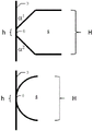
Fig. 2 shows two embodiments of the deformable sealing element of the syringe of the invention.
Fig. 3 shows a longitudinal cross-section of an embodiment of the syringe of the present invention.
Fig. 4 shows a longitudinal cross-section of an embodiment of the syringe of the present invention.
Fig. 5a and 5b show longitudinal cross-sections of an embodiment of the syringe of the present invention.
Fig. 6 shows a longitudinal cross section of an embodiment of the piston rod of the present invention.
Fig. 7 shows a longitudinal cross-section of an embodiment of the syringe of the invention having a piston rod mounted on the syringe barrel.
Fig. 8 shows a longitudinal cross-section of an embodiment of the syringe of the invention with a piston rod inserted into the syringe barrel.
Different embodiments are variations and modifications of the piston and similar parts have been provided with the same reference numerals.
Detailed Description
The invention will now be described in more detail with reference to the accompanying drawings.
Fig. 1 shows a cross section of a syringe 1. The syringe comprises a barrel 2 having an inner wall 3 and a plunger 4, the plunger 4 having two deformable sealing elements 5 with convex surfaces. The deformable sealing element 5 abuts the inner wall 3 of the cylinder 2 at an abutment interface 6 and seals the annular gap between the inner wall 3 of the cylinder 2 and the piston 4. The abutment interface 6 and the deformable sealing element 5 have an axial dimension parallel to the longitudinal axis of the cylinder 2, and the ratio between the axial dimension of the abutment interface 6 and the axial dimension of the deformable sealing element 5 is in the range between 0.01 and 0.4, for example between 0.01 and 0.2. The piston 4 shown in fig. 1 is solid and has no cavity. The piston 4 shown in fig. 1 is symmetrical with respect to a transverse plane. The piston 4 in fig. 1 has two deformable sealing elements, but the piston 4 may also have one or more than two deformable sealing elements.
In the embodiment shown, the piston 4 comprises two circumferential deformable sealing elements 5, which deformable sealing elements 5 are positioned at a distance from each other in the longitudinal direction of the piston 4, each deformable sealing element 5 abutting an end of the piston 4. Each deformable sealing element 5 comprises a convex surface extending at an angle from the piston 4 towards the inner wall 3 of the cylinder 2.
The abutment interface 6 has a height extending along the longitudinal axis of the barrel 2. As long as the ratio between the axial dimension of the abutment interface 6 and the axial dimension of the deformable sealing element 5 is within the indicated range, the abutment interface 6 of each deformable sealing element 5 may have a different height, and the abutment interface 6 of each deformable sealing element 5 need not be identical along the circumferential direction of the inner wall 3.
In the embodiment shown, the convex surface meets the inner wall at an angle, providing an approximately interrupted abutment interface 6. Since the diameter of the piston 4, including the deformable sealing element 5, is larger than the inner diameter of the cylinder 2, the abutment interface 6 provides a force exerted by the piston 4 on the inner wall 3 via the deformable sealing element 5.
The deformable sealing element 5 divides the cylinder in different sections in the longitudinal direction. The uppermost deformable sealing element 5 delimits a drive section 12 of the cylinder, into which drive section 12 a piston rod (not shown) can be inserted to move the piston 4. The lowermost deformable sealing element 5 delimits an outlet section 11, in which outlet section 11 a liquid 7 for injection, for example a pharmaceutical composition, can be located. The drive section 12 and the outlet section 11 may vary with the position of the piston 4. The deformable sealing element 5 ensures that the liquid 7 in the outlet section 11 does not pass through or past the piston 4 to the drive section 12. Although two deformable sealing elements 5 are shown, any number of deformable sealing elements 5 may be used. For example, in other embodiments, the piston 4 comprises 3, 4, 5, or more deformable sealing elements 5. In general, the more deformable sealing elements 5, the greater the force required for initial movement of the piston 4.
The cylinder includes a drive end 9 and an outlet end 8 located at each end of the cylinder 2. The driving end 9 defines the end into which the piston 4 can be initially inserted. The outlet end 8 defines the end towards which the piston 4 is moved during operation, for example to empty the syringe 1.
Here, a hypodermic needle 14 is shown preloaded at the tubular outlet 10. The tubular outlet 10 is connected to the outlet end 8 of the cylinder 2. The tubular outlet 10 may be an integral part of the barrel 2. The tubular outlet 10 may have any form that allows engagement with a hypodermic needle using suitable principles, such as attaching the hypodermic needle 14 to the barrel 2 in a male-female relationship.
The syringe 1 may further comprise a plunger rod (not shown). The piston rod enables the piston 4 to be moved towards the outlet end 8 by inserting the piston rod through the drive end 9 of the cylinder 2. By pushing the piston rod into the barrel 2, the piston 4 is moved towards the outlet end 8, forcing the liquid 7 out of the outlet section 11 through the hypodermic needle 14 or the outlet 10.
During injection of the liquid 7 from the syringe 1, a jet force is applied by, for example, a piston rod (not shown) to the drive surface of the piston 4 and in the direction of the outlet end 8 of the barrel. Since the outlet section 11 is filled with liquid 7, the liquid 7 will generate a counter force in the direction opposite to the ejection force. Thus, the piston 4 undergoes compression as a result of the injection force and the opposing force. As a result, the force on the inner wall is expanded, which causes the piston 4 and the deformable sealing element 5 to expand radially and seal more tightly against the inner wall 3, preventing the liquid 7 from passing from the outlet section 11 to the drive section 12, and also ensuring that the correct dose of liquid 7 is expelled from the syringe 1 and injected. It will be appreciated that movement of the piston 4 in the above-described direction is produced when the injection force exceeds the static friction and force produced at the abutment interface 6 by the force on the inner wall 3. Likewise, if it is attempted to refill the barrel via pressure filling through hypodermic needle 14, the opposing force must exceed the static friction created at the abutment interface 6 by the force on the inner wall 3. The initial movement of the piston 4 requires a pressure of at least about 300kPa.
The inner wall 3 of the barrel 2 comprises a lubricant, such as silicone oil or a vaccine or another pharmaceutical composition, for easier movement, for example to reduce dynamic friction of the piston 4 within the barrel 2.
Fig. 2 shows different embodiments of the deformable sealing element 5 with different shapes. In the embodiment of fig. 2, a cross-section of the deformable sealing element 5 and the inner wall 3 of the cylinder 2 is shown. The height of the deformable sealing element 5 is indicated as H. On each side of a plane (not shown) transversal to the cylinder 2, the convex surface of the deformable sealing element 5 and the inner wall 3 of the cylinder 2 define, by abutting the interface 6, a contact angle α, respectively 1 、α 2 . Angle alpha 1 、α 2 Approximately 45 deg.. Angle alpha 1 、α 2 May be in the range of about 0 ° to 50 ° and may vary independently of one another. The convex surface of the deformable sealing element 5 may be of any shape and is not limited to a straight line forming the convex surface.
The abutment interface 6 is defined by the surface where the deformable sealing element 5 abuts the inner wall 3. The abutment interface 6 has a height denoted h. The ratio between the axial dimension of the abutment interface 6 and the axial dimension of the deformable sealing element 5 is between about 0.1 and about 0.15. However, the ratio between the axial dimension of the abutment interface 6 and the axial dimension of the deformable sealing element 5 may be in the range between 0.01 and 0.4, for example between 0.01 and 0.2.
Fig. 3 shows an embodiment of the syringe of the invention, in which the piston 4 comprises a cavity 15, the cavity 15 being located adjacent to the supporting sealing element 13 and being completely or partially surrounded on all sides by the piston 4. During use, the cavity 15 may receive the tip of a piston rod (not shown) passing through a hole in the drive surface of the piston 4. The cavity 15 may be of any shape desired.
The deformable sealing element 5 and the supporting sealing element 13 may be of any shape independent of each other. In the embodiment shown, the lowermost deformable sealing element 5 has the same characteristics as the deformable sealing element 5 described in fig. 1. The uppermost supporting sealing element 13 has a different profile which results in a larger contact interface with the inner wall 3 than is required to provide a ratio between the axial dimension of the contact interface and the axial dimension of the supporting sealing element of less than 0.4. The uppermost supporting sealing element 13 does not provide a significant increase in static friction, but rather guides the piston 4 during movement to control the orientation of the piston 4 and thereby prevent leakage of liquid 7 from the outlet section 11. The supporting sealing element 13 may be made of the same material as the deformable sealing element 5 and/or the piston 4 and have the same properties regarding elasticity and stiffness. When the plunger rod is inserted into the cavity 15 to empty the syringe, the plunger rod will preferably fill the cavity 15.
In another embodiment (not shown), the piston comprises a second deformable sealing element as the uppermost sealing element, as required in the present invention. The lowermost deformable sealing element abuts the inner wall of the cartridge body at all times after being positioned in the cartridge body. However, in the rest or unloaded position of the plunger when the plunger is operated without the plunger rod, the uppermost deformable sealing element may contact the inner wall. When the piston rod is inserted into the cavity, movement of the piston towards the outlet end may produce a deformation of the piston material surrounding the cavity, which deformation is directed towards the central axis of the piston, such that the uppermost deformable sealing element "lifts" away from the inner wall. So that the uppermost deformable sealing element does not generate static friction. However, when the piston rod is not inserted in the cavity, static friction will be created by the uppermost deformable sealing element. Thus, there is more static friction that must be overcome when attempting to refill the syringe via the outlet than when using the syringe via the plunger rod to empty the barrel. This makes the syringe more convenient for the operator. In this embodiment it is preferred that the drive surface of the piston is concave, e.g. has a conical shape, and that the piston rod does not fill the cavity in order to create a "lifting effect" for the piston rod and lift the uppermost deformable sealing element away from the inner wall when the piston rod pushes the piston towards the outlet end.
Fig. 4 shows an embodiment of an injector 1 according to the invention in which the piston 4 is inserted into an injector pre-filled with a pharmaceutical composition, for example for use with NFI (needle free injector), in which the liquid 7 is injected under pressure through the skin by the drive means, and no hypodermic needle is used. This embodiment of the syringe may also be referred to as an "ampoule".
The need for a user to fill the syringe is eliminated in the embodiment of fig. 4. The syringe 1 in the embodiment shown comprises a barrel cap 16 at the outlet end 8, which barrel cap 16 ensures tightness from production and up to injection. The illustrated NFI is intended for use in a device capable of applying sufficient force, such as by pressurized air or a piston rod integrated in the device, to move a piston to an outlet end with sufficient force to create a liquid flow of a pharmaceutical composition in a barrel of a syringe to deliver the pharmaceutical composition to a subject through the skin of the subject. Such devices are known to the skilled person.
The embodiment of fig. 5a and 5b shows in cross-section a disposable cartridge representing the injector 1 of the present invention. The syringe 1 comprises a hypodermic needle 14, which hypodermic needle 14 is attached to the outlet 10 at the outlet end 8 of the barrel 2 opposite the driving end 9 of the barrel 2. The cylinder 2 has an operative length 17, which operative length 17 is defined by the distance from the driving end 9 of the cylinder 2 to the outlet end 8 of the cylinder 2 minus the dimension of the piston 4 parallel to the longitudinal axis. The syringe 1 has a plunger rod 20, the plunger rod 20 having an operating section 19 and a tubular section 18 for accommodating the hypodermic needle 14, the tubular section 18 comprising engagement means for engaging complementary engagement means of the outlet 10 or hypodermic needle 14. Fig. 5a shows the piston rod 20 mounted to accommodate the hypodermic needle 14, and the outlet section 11 pre-filled with the pharmaceutical composition. Thus, fig. 5a represents a syringe that may be delivered to an end user. Plunger rod 20 mounted on hypodermic needle 14 protects the end user from premature contact with hypodermic needle 14. In use, the piston rod 20 is removed from the hypodermic needle 14 and inserted into the drive section 12 for causing the operating section 19 of the piston rod 20 to drive the piston 4 and eject the pharmaceutical composition through the hypodermic needle 14. In the embodiment shown in fig. 5a and 5b, the piston rod 20 has a frusto-conical shape and the length of the piston rod 20 (i.e. the combined length of the tubular section 18 and the operating section 19) is longer than the operating length 17 of the barrel 2. Fig. 5b shows the piston rod 20 inserted into the cylinder 2 after emptying the cylinder 2. In a preferred embodiment, the plunger rod 20 and the barrel 2 are provided with complementary parts of a snap lock arrangement (not shown), for example at the inner wall 3 of the barrel 2, to prevent removal of the plunger rod 20 for reuse of the syringe 1.
Fig. 6 shows a plunger rod 20 of the present invention with a hypodermic needle 14 inserted into the plunger rod 20. The piston rod has a tubular section 18, which tubular section 18 is cylindrical and which has a needle insertion end 21 opposite a needle protection end 22. The needle insertion end 21 includes engagement means for engaging (e.g., via a male-female interaction in the illustrated embodiment) hypodermic needle 14. The tip of hypodermic needle 14 is inserted into elastomeric material 24, thereby sealing hypodermic needle 14. In the illustrated embodiment, the elastic material 24 has been inserted through an opening at the needle protecting end 22 of the tubular section 18. This embodiment allows the elastomeric material to be inserted after filling the pre-filled syringe. It is also possible to insert the resilient material 24 via the needle insertion end 21. The plunger rod 20 includes a thumb plate 23 at the needle protecting end 22. The thumb plate 23 of fig. 6 is shaped like an annular ring, wherein the opening of the ring allows insertion of the elastic material 24. In other embodiments, the thumb plate will have a disk shape without an opening. The piston rod 20 may be provided as shown in fig. 6, i.e. with the hypodermic needle 14 inserted into the tubular section 18, which tubular section 18 comprises the elastic material 24. This allows the hypodermic needle 14 to be mounted on the syringe (not shown) before the piston rod 20 is removed and the needle insertion end 21 is inserted into the barrel of the syringe to drive the piston in the barrel.
Fig. 7 and 8 show an embodiment of the piston rod 20, which piston rod 20 is mounted on the outlet 10 of the cylinder 2 and inserted into the cylinder 2, respectively. The piston rod has a cylindrical tubular section 18. The outer diameter of the tubular section 18 is 3.80mm and the inner diameter of the cylinder 2 is 4.60mm corresponding to a proportion of 82%. This ratio stabilizes the axial movement of the piston rod in the cylinder. The plunger rod 20 has a disc shaped thumb plate 23 at the needle protecting end 22, which thumb plate 23 increases the comfort for the user compared to a plunger rod without a thumb plate.
Figure 7 corresponds to an embodiment of the syringe of the invention in which the plunger 4 is inserted into the barrel 2 with a clearance of 10mm to the driving end 9 of the barrel. The syringe may be prefilled with a pharmaceutical composition (not shown), which may be a vaccine. The embodiment shown has a volume of 0.5ml, which is considered to be relevant for vaccines, for example when the piston 4 is inserted with a clearance of 10.00 mm. However, the volume and thus the corresponding size may be freely selected by the skilled person depending on the pharmaceutical composition adapted to the specific purpose and ejected from the syringe.
Fig. 8 shows the embodiment of fig. 7 with the piston rod 20 fully inserted into the barrel 2. In fig. 8, the operating length 17 of the barrel 2 and the length of the tubular section are selected such that once the piston rod 20 is fully inserted into the barrel 2, the thumb plate 23 is not available to retract the piston rod 20. In another embodiment (not shown), the tubular section 18 is of sufficient length to allow the piston rod 20 to be removed from the barrel 2. Since the piston rod 20 (i.e. the means for driving the piston) does not engage the piston 4, the piston rod 20 is not available for refilling the syringe. The hypodermic needle 14 can alternatively be reinserted into the piston rod 20 so that the end user or others will not be exposed to the tip of the hypodermic needle 14, thereby reducing the risk of injury or potential exposure to infectious disease.
The foregoing disclosure is illustrative of the present invention and is not to be construed as limiting thereof. While one or more embodiments of the present invention have been described, those of ordinary skill in the art will readily appreciate that many modifications are possible without departing from the scope and spirit of the disclosed invention. Accordingly, it is understood that all such modifications are intended to be included within the scope of this invention. The description and drawings illustrate one or more exemplary embodiments of the invention and are not to be construed as limiting.
Claims (15)
1. A syringe, comprising:
a barrel having a longitudinal axis and an inner wall;
a solid piston having no cavity and inserted into the barrel, the piston having a piston body and two or more deformable sealing elements each abutting the inner wall of the barrel at an abutment interface and sealing an annular gap between the inner wall of the barrel and the piston body;
a hypodermic needle attached to an outlet at an outlet end of the barrel opposite the driven end of the barrel; and
a plunger rod having a tubular section for receiving the hypodermic needle, the tubular section having a needle insertion end and a needle protection end opposite the needle insertion end, the needle insertion end comprising engagement means for engaging complementary engagement means of the outlet or the hypodermic needle, the tubular section comprising means for driving a plunger, the plunger rod having a length equal to or greater than an operational length of the barrel defined by the distance from the driving end of the barrel to the outlet end of the barrel minus a dimension of the plunger parallel to the longitudinal axis;
the means for driving the piston does not include a mechanism for engaging the piston, and the piston does not include a mechanism for engaging the means for driving the piston,
wherein the piston is symmetrical with respect to a transverse plane, and
wherein the piston is inserted into the barrel without a pre-set orientation.
2. The syringe of claim 1, wherein each deformable sealing element has a convex surface.
3. The syringe of claim 1, wherein the plunger is made of a material selected from the list comprising: thermoplastic elastomers, rubbers, and silicone rubbers.
4. The syringe of claim 1, wherein the piston has a shore a durometer in the range of 50 to 90.
5. The syringe of claim 1, wherein the plunger does not include any pigment or dye.
6. The syringe of claim 1, wherein the plunger rod has a thumb plate.
7. The syringe of claim 1, wherein the piston rod has an elastic material positioned such that a tip of the hypodermic needle is sealed by the elastic material when the hypodermic needle is inserted into the tubular section.
8. The syringe of claim 1, wherein the means for driving the plunger is at the needle insertion end.
9. The syringe of claim 1, wherein the syringe is pre-filled with a pharmaceutical composition.
10. The syringe of claim 1, wherein said piston body and said deformable sealing element are the same material.
11. The syringe of claim 1, wherein the plunger is made by injection molding.
12. The syringe of claim 11, wherein the plunger is made of a styrenic block copolymer.
13. The syringe of claim 1, wherein the inner wall of the barrel comprises a lubricant having a kinematic viscosity in a range of 100cSt to 15,000cst.
14. The syringe of claim 1, wherein the barrel has an inner diameter of up to 45 mm.
15. The syringe of claim 1, wherein the barrel has an inner diameter in the range of 2mm to 10 mm.
Applications Claiming Priority (6)
| Application Number | Priority Date | Filing Date | Title |
|---|---|---|---|
| DKPA201300342 | 2013-06-05 | ||
| DKPA201300342 | 2013-06-05 | ||
| DKPA201370433 | 2013-08-06 | ||
| DKPA201370433 | 2013-08-06 | ||
| PCT/DK2014/050161 WO2014194918A1 (en) | 2013-06-05 | 2014-06-04 | Piston for use a syringe with specific dimensional ratio of a sealing structure |
| CN201480032306.3A CN105324143B (en) | 2013-06-05 | 2014-06-04 | Piston for syringe with sealing structure of specific dimensional proportion |
Related Parent Applications (1)
| Application Number | Title | Priority Date | Filing Date |
|---|---|---|---|
| CN201480032306.3A Division CN105324143B (en) | 2013-06-05 | 2014-06-04 | Piston for syringe with sealing structure of specific dimensional proportion |
Publications (2)
| Publication Number | Publication Date |
|---|---|
| CN111467613A CN111467613A (en) | 2020-07-31 |
| CN111467613B true CN111467613B (en) | 2022-12-16 |
Family
ID=52007590
Family Applications (2)
| Application Number | Title | Priority Date | Filing Date |
|---|---|---|---|
| CN202010305601.9A Active CN111467613B (en) | 2013-06-05 | 2014-06-04 | Piston for an injection cartridge with a sealing structure of a specific dimensional ratio |
| CN201480032306.3A Active CN105324143B (en) | 2013-06-05 | 2014-06-04 | Piston for syringe with sealing structure of specific dimensional proportion |
Family Applications After (1)
| Application Number | Title | Priority Date | Filing Date |
|---|---|---|---|
| CN201480032306.3A Active CN105324143B (en) | 2013-06-05 | 2014-06-04 | Piston for syringe with sealing structure of specific dimensional proportion |
Country Status (30)
| Country | Link |
|---|---|
| US (2) | US9675764B2 (en) |
| EP (2) | EP3808396A1 (en) |
| JP (3) | JP7091022B2 (en) |
| KR (2) | KR102239086B1 (en) |
| CN (2) | CN111467613B (en) |
| AP (1) | AP2015008877A0 (en) |
| AU (2) | AU2014277300B2 (en) |
| BR (1) | BR112015029339B1 (en) |
| CA (1) | CA2914532C (en) |
| CL (1) | CL2015003411A1 (en) |
| CR (1) | CR20150617A (en) |
| CU (1) | CU20150160A7 (en) |
| DK (2) | DK3003440T3 (en) |
| DO (1) | DOP2015000285A (en) |
| EA (1) | EA036216B1 (en) |
| ES (1) | ES2861956T3 (en) |
| IL (2) | IL242696B (en) |
| MA (1) | MA38706B2 (en) |
| MX (2) | MX370596B (en) |
| MY (1) | MY179593A (en) |
| NI (1) | NI201500164A (en) |
| PE (1) | PE20160340A1 (en) |
| PH (1) | PH12015502643B1 (en) |
| PL (1) | PL3003440T3 (en) |
| PT (1) | PT3003440T (en) |
| SA (1) | SA515370157B1 (en) |
| SG (2) | SG11201509151XA (en) |
| TN (1) | TN2015000492A1 (en) |
| WO (1) | WO2014194918A1 (en) |
| ZA (2) | ZA201508670B (en) |
Families Citing this family (23)
| Publication number | Priority date | Publication date | Assignee | Title |
|---|---|---|---|---|
| KR101387795B1 (en) * | 2012-05-29 | 2014-04-22 | 고려대학교 산학협력단 | Transportation Monitoring System and Method of Construction Hoist |
| TN2015000492A1 (en) * | 2013-06-05 | 2017-04-06 | Injecto As | Piston for use a syringe with specific dimensional ratio of a sealing structure |
| WO2016192739A2 (en) * | 2015-06-03 | 2016-12-08 | Tina Hetting Holding Aps | An injector for preventing accidental needle sticks |
| US10471211B2 (en) | 2016-01-15 | 2019-11-12 | W. L. Gore & Associates, Inc. | Medical delivery device with laminated stopper |
| AU2017233270B2 (en) * | 2016-03-13 | 2022-06-16 | Injecto Group A/S | An injector with reduced break loose force |
| DE102016109505A1 (en) * | 2016-05-24 | 2017-11-30 | Gerresheimer Regensburg Gmbh | Component for a syringe and syringe |
| GB201611185D0 (en) * | 2016-06-28 | 2016-08-10 | Provensis Ltd | Reduced sputtering syringe |
| US10493207B2 (en) | 2017-02-27 | 2019-12-03 | W. L. Gore & Associates, Inc. | Medical delivery devices having low lubricant syringe barrels |
| CN106983929A (en) * | 2017-05-19 | 2017-07-28 | 四川北辰乾衡科技有限责任公司 | A kind of muscle recovery cartridge syringe |
| CN107812281B (en) * | 2017-11-17 | 2024-04-02 | 北京快舒尔医疗技术有限公司 | Needleless injector, needleless injector medicine tube and piston rod thereof |
| EP3489171A1 (en) * | 2017-11-23 | 2019-05-29 | The Procter & Gamble Company | Piston with flexible closure for aerosol container |
| CN114953652A (en) | 2017-12-15 | 2022-08-30 | 西部制药服务有限公司 | Smooth film laminated elastomeric articles |
| EP3513880B1 (en) | 2018-01-23 | 2021-08-25 | The Procter & Gamble Company | Dispensing device suitable for a foamable product |
| BR112020019255B1 (en) | 2018-03-27 | 2023-10-17 | Injecto Group A/S | INJECTOR FOR DISTRIBUTING A PHARMACEUTICAL COMPOSITION |
| US11266568B2 (en) | 2018-09-11 | 2022-03-08 | West Pharmaceutical Services, Inc. | Elastomer components containing taggants |
| US10850914B2 (en) | 2018-11-08 | 2020-12-01 | The Procter And Gamble Company | Dip tube aerosol dispenser with upright actuator |
| US11267644B2 (en) | 2018-11-08 | 2022-03-08 | The Procter And Gamble Company | Aerosol foam dispenser and methods for delivering a textured foam product |
| FR3093004B1 (en) * | 2019-02-21 | 2023-04-07 | Dev Techniques Plastiques | METHOD FOR PREPARING A SYRINGE |
| CN110192925A (en) * | 2019-05-23 | 2019-09-03 | 爱几度(深圳)科技有限公司 | A kind of water toothpick and the suction pump for water toothpick |
| CN110375067A (en) * | 2019-06-25 | 2019-10-25 | 北京北分瑞利分析仪器(集团)有限责任公司 | A kind of piston sealing structure applied to syringe |
| CN110448765A (en) * | 2019-08-30 | 2019-11-15 | 深圳安特医疗股份有限公司 | Piston component and syringe |
| US11707576B2 (en) * | 2019-09-19 | 2023-07-25 | Avent, Inc. | Plunger gasket with reduced surface contact |
| CN111888577B (en) * | 2020-08-06 | 2021-03-16 | 浙江环良医疗器械有限公司 | Medical syringe |
Citations (4)
| Publication number | Priority date | Publication date | Assignee | Title |
|---|---|---|---|---|
| US2832340A (en) * | 1957-03-26 | 1958-04-29 | American Home Prod | Syringe push rod |
| US2922419A (en) * | 1953-12-01 | 1960-01-26 | Becton Dickinson Co | Hypodermic syringe assembly |
| GB1205021A (en) * | 1966-11-25 | 1970-09-09 | Eric Katz | Improvements in or relating to hypodermic syringes |
| US4430082A (en) * | 1982-06-25 | 1984-02-07 | Hoffmann-La Roche Inc. | Hypodermic syringe assembly |
Family Cites Families (50)
| Publication number | Priority date | Publication date | Assignee | Title |
|---|---|---|---|---|
| US791802A (en) * | 1904-05-16 | 1905-06-06 | Justin De Lisle | Hypodermic syringe. |
| US2453589A (en) * | 1946-11-04 | 1948-11-09 | Noel J Poux | Hypodermic syringe and ampoule therefor |
| US2453590A (en) * | 1946-11-04 | 1948-11-09 | Noel J Poux | Hypodermic syringe |
| US2591046A (en) * | 1948-10-18 | 1952-04-01 | Frederick M Turnbull | Hypodermic syringe assembly |
| US2551339A (en) * | 1949-03-18 | 1951-05-01 | Abbott Lab | Administration of medicament |
| US2860635A (en) * | 1957-03-20 | 1958-11-18 | Edgar H Wilburn | Sterilizable and sterilized hypodermic syringe assemblies |
| US3045674A (en) | 1958-11-24 | 1962-07-24 | Graham Chemical Corp | Hypodermic syringe piston |
| US3545607A (en) | 1968-08-29 | 1970-12-08 | Becton Dickinson Co | Self-contained packaged needle assembly |
| FR1600637A (en) | 1968-12-31 | 1970-07-27 | ||
| FR2348708A1 (en) | 1976-04-23 | 1977-11-18 | Becton Dickinson France | SYRINGE BULB AND METHOD OF USE |
| US4317445A (en) | 1980-03-31 | 1982-03-02 | Baxter Travenol Laboratories, Inc. | Catheter insertion unit with separate flashback indication for the cannula |
| US4317446A (en) * | 1980-09-04 | 1982-03-02 | Schering Corporation | Prefilled disposable syringe |
| JPH02220670A (en) * | 1989-02-22 | 1990-09-03 | Terumo Corp | Medical instrument |
| IT221835Z2 (en) | 1991-04-16 | 1994-12-06 | Mc Carthy Martin Charles | DISPOSABLE SELF-LOCKING SYRINGE |
| JP3553089B2 (en) * | 1991-05-30 | 2004-08-11 | 株式会社トップ | Syringe |
| US5397313A (en) * | 1994-01-27 | 1995-03-14 | The Kendall Company | Low friction syringe |
| US5795337A (en) | 1994-02-14 | 1998-08-18 | Becton Dickinson And Company | Syringe assembly and syringe stopper |
| US7300416B2 (en) * | 1995-08-22 | 2007-11-27 | Specialized Health Products International | Pre-filled retractable needle injection ampoules |
| DE29516282U1 (en) | 1995-10-13 | 1995-12-07 | Hoechst Ag | Piston plugs for syringe barrels |
| US6004300A (en) | 1997-08-28 | 1999-12-21 | Butcher; Robert M | Composite hypodermic syringe piston |
| JP2000107290A (en) * | 1998-10-05 | 2000-04-18 | Igaku Joho Service:Kk | Injector |
| EP1002551A3 (en) | 1998-11-19 | 2000-07-05 | Bracco International B.V. | Easy-slip plunger/plunger rod assembly for a syringe or a cartridge |
| PL196150B1 (en) | 1999-01-07 | 2007-12-31 | Oresundshoj Medico Aps | Self-destructing one-use syringe |
| DE60025482T2 (en) | 1999-05-28 | 2006-09-28 | Novo Nordisk A/S | SPRAYED STOPPER FOR DRUG CONTAINERS |
| JP2001029466A (en) * | 1999-07-15 | 2001-02-06 | Hiroshi Motobayashi | Prefilled syringe |
| DE19953077B4 (en) | 1999-11-04 | 2004-02-12 | Edscha Ag | Door hinge with integrated door lock |
| JP4370045B2 (en) | 2000-06-21 | 2009-11-25 | 大成化工株式会社 | Syringe |
| DE20011366U1 (en) | 2000-06-28 | 2000-09-14 | Lin Te Fa | Syringe device |
| AUPQ867900A0 (en) | 2000-07-10 | 2000-08-03 | Medrad, Inc. | Medical injector system |
| US6511459B1 (en) | 2000-09-29 | 2003-01-28 | Mallinckrodt Inc. | Syringe plunger having an improved sealing ability |
| AU2000279374A1 (en) | 2000-10-19 | 2002-04-29 | Ali Kamagate | Secure syringe |
| JP3749197B2 (en) * | 2001-06-06 | 2006-02-22 | 株式会社トップ | Syringe |
| JP2003180832A (en) | 2001-12-20 | 2003-07-02 | Hori Glass Kk | Syringe |
| ATE520437T1 (en) | 2002-10-11 | 2011-09-15 | Becton Dickinson Co | RINSING SYRINGE WITH A BACKFLOW-INHIBITING DEVICE |
| EP1596909A2 (en) | 2003-02-27 | 2005-11-23 | Baxter International Inc. | Piston assembly for syringe |
| US20040176722A1 (en) | 2003-03-05 | 2004-09-09 | Capes David Francis | Single-use syringe |
| FR2855413B1 (en) | 2003-05-26 | 2005-12-30 | Becton Dickinson France | PRE-FILLED SYRINGE WITH ANTI-EFFRACTION COIFFE |
| JP4663791B2 (en) * | 2005-08-29 | 2011-04-06 | ウェスト ファーマシューティカル サービシズ インコーポレイテッド | Dual material plunger tip for syringe |
| US20100167231A1 (en) * | 2006-11-24 | 2010-07-01 | Dubbe John W | Piston and handheld dispenser including a piston |
| CN201022890Y (en) * | 2007-01-19 | 2008-02-20 | 江西洪达医疗器械集团有限公司 | Low-resistance syringe rubber plug |
| EP2050477B1 (en) | 2007-10-19 | 2018-12-26 | F.Hoffmann-La Roche Ag | Ampoule unit with adapter |
| WO2009128265A1 (en) * | 2008-04-16 | 2009-10-22 | 味の素株式会社 | Syringe |
| JP5131029B2 (en) | 2008-05-26 | 2013-01-30 | 富士通株式会社 | Communication apparatus and path switching method |
| US8613730B2 (en) * | 2008-11-26 | 2013-12-24 | Acist Medical Systems, Inc. | Apparatus and methods for fluid pressurizing units of injection systems |
| GB2467904B (en) * | 2009-02-17 | 2013-06-12 | Oval Medical Technologies Ltd | Drug container and delivery mechanism |
| JP5492185B2 (en) | 2009-03-09 | 2014-05-14 | テルモ株式会社 | Gasket and syringe |
| US20120172818A1 (en) | 2009-03-31 | 2012-07-05 | Sanofi-Aventis Deutschland Gmbh | Medical Device Having a Mechanism and Use of a Low-Friction Synthetic Material Within a Medical Device |
| US8469981B2 (en) | 2010-02-11 | 2013-06-25 | Ethicon Endo-Surgery, Inc. | Rotatable cutting implement arrangements for ultrasonic surgical instruments |
| US10426391B2 (en) * | 2011-10-20 | 2019-10-01 | Becton, Dickinson And Company | Blood collection cartridge, blood collection system, and blood collection method for use thereof |
| TN2015000492A1 (en) * | 2013-06-05 | 2017-04-06 | Injecto As | Piston for use a syringe with specific dimensional ratio of a sealing structure |
-
2014
- 2014-06-04 TN TN2015000492A patent/TN2015000492A1/en unknown
- 2014-06-04 CN CN202010305601.9A patent/CN111467613B/en active Active
- 2014-06-04 AP AP2015008877A patent/AP2015008877A0/en unknown
- 2014-06-04 WO PCT/DK2014/050161 patent/WO2014194918A1/en active Application Filing
- 2014-06-04 SG SG11201509151XA patent/SG11201509151XA/en unknown
- 2014-06-04 CN CN201480032306.3A patent/CN105324143B/en active Active
- 2014-06-04 ES ES14731149T patent/ES2861956T3/en active Active
- 2014-06-04 US US14/895,272 patent/US9675764B2/en active Active
- 2014-06-04 PT PT147311492T patent/PT3003440T/en unknown
- 2014-06-04 CA CA2914532A patent/CA2914532C/en active Active
- 2014-06-04 PE PE2015002432A patent/PE20160340A1/en not_active Application Discontinuation
- 2014-06-04 AU AU2014277300A patent/AU2014277300B2/en active Active
- 2014-06-04 SG SG10201801526UA patent/SG10201801526UA/en unknown
- 2014-06-04 JP JP2016517170A patent/JP7091022B2/en active Active
- 2014-06-04 BR BR112015029339-5A patent/BR112015029339B1/en active IP Right Grant
- 2014-06-04 MX MX2015015887A patent/MX370596B/en active IP Right Grant
- 2014-06-04 MY MYPI2015002821A patent/MY179593A/en unknown
- 2014-06-04 DK DK14731149.2T patent/DK3003440T3/en active
- 2014-06-04 EP EP20212195.0A patent/EP3808396A1/en active Pending
- 2014-06-04 EP EP14731149.2A patent/EP3003440B1/en active Active
- 2014-06-04 PL PL14731149T patent/PL3003440T3/en unknown
- 2014-06-04 KR KR1020207028993A patent/KR102239086B1/en active IP Right Grant
- 2014-06-04 KR KR1020157033635A patent/KR102166249B1/en active IP Right Grant
- 2014-06-04 EA EA201592218A patent/EA036216B1/en not_active IP Right Cessation
- 2014-12-19 DK DK201470805A patent/DK178284B1/en active
-
2015
- 2015-11-17 SA SA515370157A patent/SA515370157B1/en unknown
- 2015-11-18 MX MX2019011030A patent/MX2019011030A/en unknown
- 2015-11-19 IL IL242696A patent/IL242696B/en active IP Right Grant
- 2015-11-19 CR CR20150617A patent/CR20150617A/en unknown
- 2015-11-20 DO DO2015000285A patent/DOP2015000285A/en unknown
- 2015-11-20 CL CL2015003411A patent/CL2015003411A1/en unknown
- 2015-11-20 NI NI201500164A patent/NI201500164A/en unknown
- 2015-11-23 CU CUP2015000160A patent/CU20150160A7/en unknown
- 2015-11-25 ZA ZA2015/08670A patent/ZA201508670B/en unknown
- 2015-11-26 PH PH12015502643A patent/PH12015502643B1/en unknown
- 2015-12-22 MA MA38706A patent/MA38706B2/en unknown
-
2016
- 2016-12-13 ZA ZA2016/08612A patent/ZA201608612B/en unknown
-
2017
- 2017-05-08 US US15/589,784 patent/US10569030B2/en active Active
-
2019
- 2019-03-04 AU AU2019201477A patent/AU2019201477B2/en active Active
-
2020
- 2020-03-17 IL IL273363A patent/IL273363B/en active IP Right Grant
- 2020-10-22 JP JP2020177366A patent/JP7171076B2/en active Active
-
2022
- 2022-01-28 JP JP2022011753A patent/JP7384467B2/en active Active
Patent Citations (4)
| Publication number | Priority date | Publication date | Assignee | Title |
|---|---|---|---|---|
| US2922419A (en) * | 1953-12-01 | 1960-01-26 | Becton Dickinson Co | Hypodermic syringe assembly |
| US2832340A (en) * | 1957-03-26 | 1958-04-29 | American Home Prod | Syringe push rod |
| GB1205021A (en) * | 1966-11-25 | 1970-09-09 | Eric Katz | Improvements in or relating to hypodermic syringes |
| US4430082A (en) * | 1982-06-25 | 1984-02-07 | Hoffmann-La Roche Inc. | Hypodermic syringe assembly |
Also Published As
Similar Documents
| Publication | Publication Date | Title |
|---|---|---|
| CN111467613B (en) | Piston for an injection cartridge with a sealing structure of a specific dimensional ratio | |
| CN109414550B (en) | Syringe with reduced break-away force | |
| CN107847679B (en) | Syringe for preventing accidental needle stick injuries | |
| OA18656A (en) | Piston for Use a syringe with specific dimensional ratio of a sealing structure. | |
| OA18776A (en) | An injector for preventing accidental needle sticks. |
Legal Events
| Date | Code | Title | Description |
|---|---|---|---|
| PB01 | Publication | ||
| PB01 | Publication | ||
| SE01 | Entry into force of request for substantive examination | ||
| SE01 | Entry into force of request for substantive examination | ||
| GR01 | Patent grant | ||
| GR01 | Patent grant |