Disclosure of Invention
The invention aims to provide welding and assembling equipment for an LED lamp tube, which is used for overcoming the defects in the prior art.
The welding and assembling device for the LED lamp tube comprises a machine body, wherein a conveying cavity is arranged in the machine body, a driving belt wheel is rotatably arranged at the lower side of the conveying cavity, a conveying belt for conveying the LED lamp is arranged on the driving belt wheel, a tray for placing the LED lamp is arranged at the upper side of the conveying belt, the LED lamp tube is fixedly arranged on the tray, lamp wicks are arranged in the LED lamp tube, symmetrical lamp wick welding and installing devices are arranged at the left side and the right side of the conveying cavity, each lamp wick welding and installing device comprises welding cavities symmetrically arranged at the left side and the right side of the conveying cavity, a rotary table for welding and installing is rotatably arranged in each welding cavity, a welding disc for welding is arranged at the center of the upper side of the rotary table, a fixing frame for installing a lamp cover is fixedly arranged at the rear side of the welding disc at the upper side of the rotary table, a metal wire is fixedly arranged at the, a supporting plate for supporting the lamp wick is fixedly arranged in the rear side wall of the welding cavity, a gear cavity for gear transmission is arranged at the lower side of the welding cavity at the left side of the LED lamp tube, a right gear cavity for gear transmission is arranged at the lower side of the welding cavity at the right side of the LED lamp tube, a conveying shaft fixedly mounted with the conveying belt wheel in the conveying cavity is rotatably arranged between the gear cavity and the right gear cavity, a control motor is fixedly arranged in the left side wall of the gear cavity, a first belt wheel is fixedly arranged on a power output shaft of the control motor, symmetrical gear sets for conveying transmission are arranged at the lower side of the welding cavity, the gear sets comprise a sliding sleeve which is arranged on the conveying shaft in the gear cavity and is in threaded connection with the sliding sleeve, a second belt wheel is connected on the sliding sleeve in the gear cavity through a spline, and a synchronous belt is arranged between the second, and a welding clamping device used for welding the metal wire is arranged in the wall body on the upper side of the welding cavity, and a push rod mounting device used for mounting an LED lamp is arranged on one side, far away from the LED lamp tube, in the welding cavity.
On the basis of the technical scheme, the gear set comprises the sliding sleeve, symmetrical threads are arranged on the left side and the right side of the transportation shaft, a threaded gear is connected to the threads through a spline, the sliding sleeve is fixedly arranged on the left side of the threaded gear in the gear cavity, a right moving sleeve is fixedly arranged on the right side of the threaded gear in the right gear cavity, symmetrical moving bevel gears are arranged on the left side and the right side of the transportation shaft in a sliding manner, the left side of the sliding sleeve is fixedly arranged with the moving bevel gears in the gear cavity, the right side of the right moving sleeve is fixedly arranged with the moving bevel gears in the right gear cavity, a displacement wheel which is slidably arranged with the outer side wheel of the threaded gear is rotatably arranged in the wall body on the right side of the gear cavity, and the sliding sleeve and the moving bevel gears can slide outwards or inwards simultaneously on the displacement wheel, the rotary table is characterized in that bilaterally symmetrical rotary table shafts are fixedly arranged on the lower side of the rotary table, upper bevel gears are fixedly arranged on the lower side of the rotary table shafts, and rotary table devices used for rotary reset of the rotary table are arranged in the welding cavity.
On the basis of the technical scheme, the welding clamping device comprises the welding disc, a wire clamping box is arranged on the upper side of the welding cavity in a sliding mode, the wire clamping box is close to one side of the LED lamp tube, a rotating motor is fixedly arranged in the machine body, a downward shifting gear cavity is arranged on the rear side of the wire clamping box, a power output shaft of the rotating motor and a downward shifting gear in the downward shifting gear cavity are fixedly arranged, the downward shifting gear is meshed with a rear side rack arranged on the rear side of the wire clamping box and is connected with an inner side gear cavity, a transmission cavity is arranged on the left side of the inner side gear cavity, a central gear cavity is arranged on the lower side of the inner side gear cavity, inner side gears are rotatably arranged on the left side wall body and the right side wall body of the inner side gear cavity, a rebounder for assisting the wire clamping box to reset is arranged on the right side of the inner side gear, a first small belt wheel is fixedly arranged, the transmission intracavity first minipulley downside rotates and is equipped with the minipulley of second, first minipulley with be equipped with little hold-in range between the minipulley of second, first minipulley right side the sun gear intracavity has set firmly sun gear, the sun gear upside is equipped with the clamping bar chamber, the sliding of clamping bar intracavity be equipped with the rear side clamping bar that sun gear meshing is connected, the sun gear downside is equipped with the front side clamping bar chamber, the sliding of front side clamping bar intracavity be equipped with the front side clamping bar that sun gear meshing is connected, the clamping bar case right side has set firmly the welding case, the welding case downside sets firmly be used for the wire carries out welded soldered connection.
On the basis of the technical scheme, the rotary table device comprises a rotary table, a recovery cavity is arranged on the lower side of the welding cavity, the recovery cavity is close to a lower side gear cavity arranged in a wall body on one side of the LED lamp tube, a driven shaft is arranged between the recovery cavity and the lower side gear cavity in a rotating mode, the driven shaft is far away from a side thread arranged on one side of the LED lamp tube, a moving rotating wheel is connected to the side thread in a meshed mode, the recovery cavity is far away from a wall body on one side of the LED lamp tube and a torque spring capable of storing force is arranged between the moving rotating wheel, a lower side gear is fixedly arranged on the driven shaft in the lower side gear cavity, and the lower side gear is connected with a rotary table gear fixedly arranged on the lower.
On the basis of the technical scheme, the push rod mounting device comprises a push slide rod cavity arranged in a wall body at one side of the welding cavity far away from the LED lamp tube, a push rod gear cavity is arranged at the lower side of the push slide rod cavity, a belt wheel cavity is arranged in a wall body at one side of the recovery cavity far away from the LED lamp tube, a push slide rod is arranged in the push slide rod cavity in a sliding manner, a push rod motor is fixedly arranged in the front side wall body of the push rod gear cavity, a push rod gear meshed and connected with a lower side rack arranged in the wall body at the lower side of the push slide rod is fixedly arranged on a power output shaft of the push rod motor, an unidirectional rotating shaft which can only rotate anticlockwise is arranged in the front side wall body and the rear side wall body of the belt wheel cavity at the lower side of the push slide rod in a rotating manner, a spring cavity is arranged, the utility model discloses a LED fluorescent lamp, including LED fluorescent lamp tube, one-way pivot, inside and outside tooth runner, upside belt pulley downside, upside belt pulley, downside wheel, rear side gear close to in LED fluorescent lamp tube one side rotate around the band pulley chamber on the lateral wall body be equipped with the semi-gear that rear side gear engagement is connected, the semi-gear close to in LED fluorescent lamp tube one side is equipped with smooth chamber, slide in the smooth chamber slide be equipped with the slip kelly that semi-gear engagement is connected, slip kelly downside with be equipped with expanding spring between the smooth chamber diapire.
The invention has the beneficial effects that: the LED lamp welding device is provided with the turntable device and the gear set, the LED lamp can be transmitted through the displacement wheel and effectively matched with the rotation of the turntable, and the welding process of the metal wire is quicker and more efficient;
the push rod mounting device is arranged and can be matched with the rotary table device, so that after the lamp cover of the LED lamp is mounted, the rotary table is quickly reset, the welding can be continuously carried out, and the welding and assembling efficiency of the LED lamp is greatly improved.
Detailed Description
The invention will now be described in detail with reference to fig. 1-7, for convenience of description, the following orientations will now be defined: the up, down, left, right, and front-back directions described below correspond to the up, down, left, right, and front-back directions in the projection relationship of fig. 1 itself.
Referring to fig. 1-7, the welding and assembling device for LED lamp tubes according to the embodiment of the present invention includes a machine body 10, a transportation cavity 11 is provided in the machine body 10, a transmission belt wheel 29 is rotatably provided at a lower side of the transportation cavity 11, a conveyor belt 30 for transporting LED lamps is provided on the transmission belt wheel 29, a tray 28 for placing LED lamps is provided at an upper side of the conveyor belt 30, LED lamp tubes 12 are fixedly mounted on the tray 28, lamp wicks 13 are provided in the LED lamp tubes 12, symmetrical wick welding and mounting devices 901 are provided at left and right sides of the transportation cavity 11, the wick welding and mounting devices 901 include welding cavities 84 symmetrically provided at left and right sides of the transportation cavity 11, a turntable 32 for welding and mounting is rotatably provided in the welding cavities 84, a welding disk 81 for welding is provided at a central position of an upper side of the turntable 32, a fixing frame 79 for mounting a lamp cover 78 is fixedly provided at a rear side of the welding disk 81 at an, the front side of the lamp cover 78 is fixedly provided with a metal wire 80, the fixed frame 79 is rotatably provided with a spring push plate 89 capable of being pushed to open, the back side wall of the welding cavity 84 is internally and fixedly provided with a support plate 14 for supporting the lamp wick 13, the lower side of the welding cavity 84 positioned at the left side of the LED lamp tube 12 is provided with a gear cavity 26 for gear transmission, the lower side of the welding cavity 84 positioned at the right side of the LED lamp tube 12 is provided with a right gear cavity 85 for gear transmission, a conveying shaft 31 fixedly installed with the conveying belt wheel 29 in the conveying cavity 11 is rotatably arranged between the gear cavity 26 and the right gear cavity 85, the left side wall body of the gear cavity 26 is internally and fixedly provided with a control motor 19, a power output shaft of the control motor 19 is fixedly provided with a first belt wheel 20, the lower side of the welding cavity 84 is provided with a symmetrical gear set 902 for conveying transmission, the gear set 902 comprises a sliding sleeve 23 which is arranged in the conveying shaft, a second belt wheel 22 is connected to the sliding sleeve 23 in the gear cavity 26 through a spline, a synchronous belt 21 is arranged between the second belt wheel 22 and the first belt wheel 20, a welding clamping device 903 used for welding the metal wire 80 is arranged in the wall body on the upper side of the welding cavity 84, and a push rod mounting device 904 used for mounting an LED lamp is arranged on one side, far away from the LED lamp tube 12, in the welding cavity 84.
In addition, in an embodiment, the gear set 902 includes the sliding sleeve 23, the left and right sides of the transportation shaft 31 are provided with symmetrical threads 27, the threads 27 are connected with threaded gears 25 through splines, the left side of the threaded gear 25 in the gear cavity 26 is fixedly provided with the sliding sleeve 23, the right side of the threaded gear 25 in the right gear cavity 85 is fixedly provided with a right moving sleeve 86, the left and right sides of the transportation shaft 31 are slidably provided with symmetrical moving bevel gears 18, the left side of the sliding sleeve 23 is fixedly mounted with the moving bevel gear 18 in the gear cavity 26, the right side of the right moving sleeve 86 is fixedly mounted with the moving bevel gear 18 in the right gear cavity 85, the right wall body of the right side of the gear cavity 26 is rotatably provided with a displacement wheel 24 slidably mounted with the outer wheel of the threaded gear 25, the left wall body of the right gear cavity 85 is rotatably provided with the displacement wheel 24 slidably mounted with the outer wheel of the threaded gear 25, the displacement wheel 24 can make the sliding sleeve 23 and the mobile bevel gear 18 slide outwards or inwards simultaneously, the lower side of the rotary table 32 is fixedly provided with a rotary table shaft 15 which is bilaterally symmetrical, the lower side of the rotary table shaft 15 is fixedly provided with an upper bevel gear 17, the welding cavity 84 is internally provided with a rotary table device 801 for resetting the rotary table 32 in a rotating way, when the control motor 19 is started, the first belt wheel 20 is driven to rotate, the synchronous belt 21 drives the second belt wheel 22 to rotate, the second belt wheel 22 is driven to rotate, the sliding sleeve 23 drives the sliding sleeve 23 to rotate, the sliding sleeve 23 drives the threaded gear 25 to rotate, the threaded gear 25 drives the conveying shaft 31 to rotate, the conveying shaft 31 drives the driving belt wheel 29 to rotate, so as to drive the LED lamp tube 12 to move backwards, the threaded gear 25 drives the displacement wheel 24 to rotate, so that the threaded gear 25 is separated from the thread 27 when the lamp, at this time, the traveling bevel gear 18 is in meshing engagement with the upper bevel gear 17.
In addition, in one embodiment, the welding clamping device 903 includes the welding disc 81, the upper side of the welding cavity 84 is slidably provided with a wire clamping box 54, the wire clamping box 54 is fixedly provided with a rotating motor 58 in the body 10 close to one side of the LED tube 12, the rear side of the wire clamping box 54 is provided with a downward shifting gear cavity 63, a power output shaft of the rotating motor 58 is fixedly mounted with a downward shifting gear 64 in the downward shifting gear cavity 63, the downward shifting gear 64 is engaged with a rear side rack 62 arranged at the rear side of the wire clamping box 54, an inner side gear cavity 60 is arranged in the wire clamping box 54, the left side of the inner side gear cavity 60 is provided with a transmission cavity 55, the lower side of the inner side gear cavity 60 is provided with a central gear cavity 68, inner side gears 61 are rotatably arranged on left and right side wall bodies of the inner side gear cavity 60, the right side of the inner side gear 61 in the inner side gear cavity 60 is provided with a resilient means 87 for assisting the wire, a first small belt wheel 56 is fixedly arranged in the transmission cavity 55 at the left side of the inner side gear 61, a second small belt wheel 59 is rotatably arranged at the lower side of the first small belt wheel 56 in the transmission cavity 55, a small synchronous belt 57 is arranged between the first small belt wheel 56 and the second small belt wheel 59, a central gear 67 is fixedly arranged in a central gear cavity 68 at the right side of the first small belt wheel 56, a clamping rod cavity 66 is arranged at the upper side of the central gear 67, a rear clamping rod 65 meshed and connected with the central gear 67 is slidably arranged in the clamping rod cavity 66, a front clamping rod cavity 70 is arranged at the lower side of the central gear 67, a front clamping rod 69 meshed and connected with the central gear 67 is slidably arranged in the front clamping rod cavity 70, a welding box 82 is fixedly arranged at the right side of the clamping box 54, a welding head 83 used for welding the metal wire 80 is fixedly arranged at the lower side of the welding box 82, and the inner side gear cavity 60 is driven to rotate when the rotating motor 58 is started, the inner side gear cavity 60 rotates to drive the first small belt wheel 56 to rotate, the first small belt wheel 56 rotates to drive the small synchronous belt 57 to rotate, the small synchronous belt 57 rotates to drive the second small belt wheel 59 to rotate, the second small belt wheel 59 rotates to drive the central gear cavity 68 to rotate, the central gear cavity 68 rotates to drive the rear clamping rod 65 and the front clamping rod 69 to clamp and fix the metal wire 80, and therefore the welding head 83 can weld the metal wire 80 more firmly and reliably.
In addition, in one embodiment, the turntable device 801 includes the turntable 32, a recovery cavity 88 is disposed at a lower side of the welding cavity 84, a lower gear cavity 46 is disposed in a wall body of the recovery cavity 88 near one side of the LED lamp 12, a driven shaft 48 is rotatably disposed between the recovery cavity 88 and the lower gear cavity 46, a side thread 50 is disposed at a side of the driven shaft 48 far away from the LED lamp 12, a moving wheel 49 is engaged and connected to the side thread 50, a torque spring 51 capable of accumulating force is disposed between a wall body of the recovery cavity 88 far away from the LED lamp 12 and the moving wheel 49, a lower gear 47 is fixedly disposed on the driven shaft 48 in the lower gear cavity 46, the lower gear 47 is engaged and connected to a turntable gear 16 fixedly disposed at a lower side of the turntable 32, and when the welding of the metal wire 80 of the LED lamp is completed, the control motor 19 is started, the motor 19 is controlled to start so that the sliding sleeve 23 and the right gear cavity 85 rotate to drive the movable bevel gear 18 to rotate, the movable bevel gear 18 rotates to drive the upper bevel gear 17 to rotate, the upper bevel gear 17 rotates to drive the rotary plate shaft 15 to rotate, the rotary plate shaft 15 rotates to drive the rotary plate 32 to rotate, so that the lamp cover 78 is driven to rotate to a position opposite to the push slide rod 34, meanwhile, the rotary plate shaft 15 drives the rotary plate gear 16 to rotate, the rotary plate gear 16 rotates to drive the lower gear 47 to rotate, the lower gear 47 rotates to drive the driven shaft 48 to rotate, the driven shaft 48 rotates to drive the movable rotary wheel 49 to rotate, so that the torque spring 51 stores force, and when the movable rotary wheel 49 rotates, the sliding.
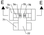
In addition, in one embodiment, the push rod mounting device 904 includes a push sliding rod cavity 33 disposed in a wall body of the welding cavity 84 far away from one side of the LED lamp tube 12, a push rod gear cavity 52 is disposed at a lower side of the push sliding rod cavity 33, a pulley cavity 38 is disposed in a wall body of the recovery cavity 88 far away from one side of the LED lamp tube 12, a push sliding rod 34 is slidably disposed in the push sliding rod cavity 33, a push rod motor 36 is fixedly disposed in a front side wall body of the push rod gear cavity 52, a push rod gear 53 engaged with a lower rack 35 disposed in a lower side wall body of the push sliding rod 34 is fixedly disposed on a power output shaft of the push rod motor 36, a one-way rotating shaft 77 capable of rotating only counterclockwise is rotatably disposed in the front side wall body and the rear side wall body of the pulley cavity 38 at a lower side of the push sliding rod 34, a spring cavity 76 is disposed in the one, a telescopic pressure spring 75 is arranged between the lower side of the right-angle gear 74 and the inner side wall body of the spring cavity 76, an inner and outer gear rotating wheel 72 is rotatably arranged at the outer side of the one-way rotating shaft 77, an inner side gear 73 at the joint of the inner side gear 72 and the outer side gear 74 is arranged at the inner side of the inner and outer gear rotating wheel 72, an upper side belt wheel 71 is fixedly arranged at the front side of the one-way rotating shaft 77, a lower side belt wheel 41 is rotatably arranged at the lower side of the upper side belt wheel 71, a belt 37 is arranged between the upper side belt wheel 71 and the lower side belt wheel 41, a rear side gear 40 is fixedly arranged at the rear side of the lower side belt wheel 41, a half gear 39 connected with the rear side gear 40 in a meshed manner is rotatably arranged on the front and rear side wall body of the belt wheel cavity 38 at one side of the LED lamp tube 12, a sliding cavity 45 is arranged at one side of, an expansion spring 43 is arranged between the lower side of the sliding clamping rod 44 and the bottom wall of the sliding cavity 45, when the push rod motor 36 is started, the push rod gear 53 rotates to drive the slide rod 34 to slide towards the side close to the LED lamp tube 12, the slide rod 34 slides towards the side close to the LED lamp tube 12, the lamp cover 78 is pushed to slide out and the LED lamp tube 12 is installed, when the installation is completed, the push rod motor 36 is started to rotate reversely, the push rod motor 36 rotates to drive the push rod gear 53 to rotate, the push rod gear 53 rotates to drive the slide rod 34 to rotate towards the side far away from the LED lamp tube 12, so that the inner and outer toothed wheels 72 are driven to rotate, the inner toothed wheels 72 rotate to drive the inner toothed wheels 73 to rotate, the inner toothed wheels 73 rotate to drive the right angled teeth 74 to rotate, the right angled teeth 74 rotate to drive the one-way rotating shaft 77 to rotate, the one-, the belt 37 rotates to drive the lower belt wheel 41 to rotate, the lower belt wheel 41 rotates to drive the rear gear 40 to rotate, the rear gear 40 rotates to drive the half gear 39 to rotate, the half gear 39 rotates to drive the sliding clamping rod 44 to move downwards, so that the sliding clamping rod 44 slides downwards to enable the moving rotating wheel 49 to be separated from the butt joint, and the turntable device 801 is started to reset.
In the initial state, the thread wheel 25 is in splined connection with the thread 27, the wire clamping box 54 is arranged on the upper side in the upper side wall of the welding cavity 84, the movable rotating wheel 49 is arranged on the right side of the recovery cavity 88, and the upper bevel gear 17 is not in meshed connection with the movable bevel gear 18.
When the LED lamp tube is transported, the control motor 19 is started first, the control motor 19 drives the first belt pulley 20 to rotate when being started, the first belt pulley 20 rotates to drive the synchronous belt 21 to rotate, the synchronous belt 21 rotates to drive the second belt pulley 22 to rotate, the second belt pulley 22 rotates to drive the sliding sleeve 23 to rotate, the sliding sleeve 23 rotates to drive the threaded gear 25 to rotate, the threaded gear 25 rotates to drive the transport shaft 31 to rotate, the transport shaft 31 rotates to drive the transmission belt pulley 29 to rotate, the LED lamp tube 12 is driven to move towards the rear side, the threaded gear 25 rotates to drive the displacement wheel 24 to rotate, so that the threaded gear 25 is separated from the threads 27 when the lamp tube 13 moves to the middle position of the rotary table 32, the transport shaft 31 stops rotating, and the movable bevel gear 18 is meshed with the.
When welding LED lamp tube metal wire 80, start earlier and rotate motor 58, it rotates to rotate motor 58 when starting to drive inboard gear chamber 60, inboard gear chamber 60 rotates and drives first minipulley 56 and rotate, first minipulley 56 rotates and drives little hold-in range 57 and rotate, little hold-in range 57 rotates and drives second minipulley 59 and rotate, second minipulley 59 rotates and drives central gear chamber 68 and rotate, central gear chamber 68 rotates and drives rear side clamping bar 65 and front side clamping bar 69 and steps up fixedly to metal wire 80, thereby make soldered connection 83 weld metal wire 80 on the welded disc 81.
When the lamp cover 78 is installed, the control motor 19 is first started, the control motor 19 is started so that the sliding sleeve 23 and the right gear cavity 85 rotate to drive the movable bevel gear 18 to rotate, the movable bevel gear 18 rotates to drive the upper bevel gear 17 to rotate, the upper bevel gear 17 rotates to drive the turntable shaft 15 to rotate, the turntable shaft 15 rotates to drive the turntable 32 to rotate, thereby driving the lamp cover 78 to rotate to a position right opposite to the push slide bar 34, simultaneously the turntable shaft 15 drives the turntable gear 16 to rotate, the turntable gear 16 rotates to drive the lower gear 47 to rotate, the lower gear 47 rotates to drive the driven shaft 48 to rotate, the driven shaft 48 rotates to drive the movable runner 49 to rotate so as to accumulate the torque spring 51, when the movable runner 49 rotates to drive the sliding clamping bar 44 to abut against and stop rotating, when the push rod motor 36 is started, the push rod gear 53 rotates to push the slide bar 34 to a side close to the LED lamp 12, the push rod 34 slides towards one side close to the LED lamp tube 12, the lamp cover 78 slides out and the LED lamp tube 12 is installed, when the installation is completed, the push rod motor 36 is started to rotate reversely, the push rod motor 36 rotates to drive the push rod gear 53 to rotate, the push rod gear 53 rotates to drive the push rod 34 to rotate towards one side far away from the LED lamp tube 12, so as to drive the inner and outer toothed wheels 72 to rotate, the inner toothed wheel 72 rotates to drive the inner teeth 73 to rotate, the inner teeth 73 rotates to drive the right-angled teeth 74 to rotate, the right-angled teeth 74 rotates to drive the one-way rotating shaft 77 to rotate, the one-way rotating shaft 77 rotates to drive the upper belt wheel 71 to rotate, the upper belt wheel 71 rotates to drive the belt 37 to rotate, the belt 37 rotates to drive the lower belt wheel 41 to rotate, the lower belt wheel 41 rotates to drive the rear gear 40 to rotate, the rear gear 40 rotates to drive the half gear 39 to rotate, the half, therefore, the turntable device 801 is started to reset, and the LED lamp tube can be welded in a production line mode by repeating the process.
The invention has the beneficial effects that: the LED lamp welding device is provided with the turntable device and the gear set, the LED lamp can be transmitted through the displacement wheel and effectively matched with the rotation of the turntable, and the welding process of the metal wire is quicker and more efficient; the push rod mounting device is arranged and can be matched with the rotary table device, so that after the lamp cover of the LED lamp is mounted, the rotary table is quickly reset, the welding can be continuously carried out, and the welding and assembling efficiency of the LED lamp is greatly improved.
The above description is only for the purpose of illustrating the preferred embodiments of the present invention and is not to be construed as limiting the invention, and any modifications, equivalents, improvements and the like that fall within the spirit and scope of the present invention are intended to be included therein.