CN111433022B - Projection device for a head-up display (HUD) using p-polarized radiation - Google Patents
Projection device for a head-up display (HUD) using p-polarized radiation Download PDFInfo
- Publication number
- CN111433022B CN111433022B CN201980003505.4A CN201980003505A CN111433022B CN 111433022 B CN111433022 B CN 111433022B CN 201980003505 A CN201980003505 A CN 201980003505A CN 111433022 B CN111433022 B CN 111433022B
- Authority
- CN
- China
- Prior art keywords
- layer
- thickness
- projection device
- glass pane
- reflectivity
- Prior art date
- Legal status (The legal status is an assumption and is not a legal conclusion. Google has not performed a legal analysis and makes no representation as to the accuracy of the status listed.)
- Active
Links
- 230000005855 radiation Effects 0.000 title claims abstract description 59
- 239000010410 layer Substances 0.000 claims abstract description 339
- 239000011521 glass Substances 0.000 claims abstract description 149
- 238000000576 coating method Methods 0.000 claims abstract description 83
- 239000011248 coating agent Substances 0.000 claims abstract description 73
- 239000002131 composite material Substances 0.000 claims abstract description 70
- 238000002310 reflectometry Methods 0.000 claims abstract description 35
- 239000012799 electrically-conductive coating Substances 0.000 claims abstract description 22
- 230000003595 spectral effect Effects 0.000 claims abstract description 20
- 229920001169 thermoplastic Polymers 0.000 claims abstract description 14
- 239000004416 thermosoftening plastic Substances 0.000 claims abstract description 13
- 239000011229 interlayer Substances 0.000 claims abstract description 12
- XLOMVQKBTHCTTD-UHFFFAOYSA-N Zinc monoxide Chemical compound [Zn]=O XLOMVQKBTHCTTD-UHFFFAOYSA-N 0.000 claims description 40
- 229910052581 Si3N4 Inorganic materials 0.000 claims description 32
- 238000009499 grossing Methods 0.000 claims description 25
- 229910052709 silver Inorganic materials 0.000 claims description 23
- 239000004332 silver Substances 0.000 claims description 23
- 150000004767 nitrides Chemical class 0.000 claims description 21
- 230000004888 barrier function Effects 0.000 claims description 20
- 239000011787 zinc oxide Substances 0.000 claims description 20
- UVGLBOPDEUYYCS-UHFFFAOYSA-N silicon zirconium Chemical group [Si].[Zr] UVGLBOPDEUYYCS-UHFFFAOYSA-N 0.000 claims description 15
- CEPICIBPGDWCRU-UHFFFAOYSA-N [Si].[Hf] Chemical compound [Si].[Hf] CEPICIBPGDWCRU-UHFFFAOYSA-N 0.000 claims description 10
- HQVNEWCFYHHQES-UHFFFAOYSA-N silicon nitride Chemical compound N12[Si]34N5[Si]62N3[Si]51N64 HQVNEWCFYHHQES-UHFFFAOYSA-N 0.000 claims description 7
- PXHVJJICTQNCMI-UHFFFAOYSA-N Nickel Chemical compound [Ni] PXHVJJICTQNCMI-UHFFFAOYSA-N 0.000 claims description 6
- RTAQQCXQSZGOHL-UHFFFAOYSA-N Titanium Chemical compound [Ti] RTAQQCXQSZGOHL-UHFFFAOYSA-N 0.000 claims description 6
- 229910052719 titanium Inorganic materials 0.000 claims description 6
- 239000010936 titanium Substances 0.000 claims description 6
- ATJFFYVFTNAWJD-UHFFFAOYSA-N Tin Chemical compound [Sn] ATJFFYVFTNAWJD-UHFFFAOYSA-N 0.000 claims description 4
- 229910045601 alloy Inorganic materials 0.000 claims description 4
- 239000000956 alloy Substances 0.000 claims description 4
- 229910052718 tin Inorganic materials 0.000 claims description 4
- XOLBLPGZBRYERU-UHFFFAOYSA-N tin dioxide Chemical compound O=[Sn]=O XOLBLPGZBRYERU-UHFFFAOYSA-N 0.000 claims description 4
- 229910001887 tin oxide Inorganic materials 0.000 claims description 4
- VYZAMTAEIAYCRO-UHFFFAOYSA-N Chromium Chemical compound [Cr] VYZAMTAEIAYCRO-UHFFFAOYSA-N 0.000 claims description 3
- GYHNNYVSQQEPJS-UHFFFAOYSA-N Gallium Chemical compound [Ga] GYHNNYVSQQEPJS-UHFFFAOYSA-N 0.000 claims description 3
- XUIMIQQOPSSXEZ-UHFFFAOYSA-N Silicon Chemical compound [Si] XUIMIQQOPSSXEZ-UHFFFAOYSA-N 0.000 claims description 3
- HCHKCACWOHOZIP-UHFFFAOYSA-N Zinc Chemical compound [Zn] HCHKCACWOHOZIP-UHFFFAOYSA-N 0.000 claims description 3
- QCWXUUIWCKQGHC-UHFFFAOYSA-N Zirconium Chemical compound [Zr] QCWXUUIWCKQGHC-UHFFFAOYSA-N 0.000 claims description 3
- 229910052804 chromium Inorganic materials 0.000 claims description 3
- 239000011651 chromium Substances 0.000 claims description 3
- 229910052733 gallium Inorganic materials 0.000 claims description 3
- 229910052735 hafnium Inorganic materials 0.000 claims description 3
- VBJZVLUMGGDVMO-UHFFFAOYSA-N hafnium atom Chemical compound [Hf] VBJZVLUMGGDVMO-UHFFFAOYSA-N 0.000 claims description 3
- 229910052738 indium Inorganic materials 0.000 claims description 3
- APFVFJFRJDLVQX-UHFFFAOYSA-N indium atom Chemical compound [In] APFVFJFRJDLVQX-UHFFFAOYSA-N 0.000 claims description 3
- 229910052759 nickel Inorganic materials 0.000 claims description 3
- 229910052758 niobium Inorganic materials 0.000 claims description 3
- 239000010955 niobium Substances 0.000 claims description 3
- GUCVJGMIXFAOAE-UHFFFAOYSA-N niobium atom Chemical compound [Nb] GUCVJGMIXFAOAE-UHFFFAOYSA-N 0.000 claims description 3
- 229910052710 silicon Inorganic materials 0.000 claims description 3
- 239000010703 silicon Substances 0.000 claims description 3
- 239000011135 tin Substances 0.000 claims description 3
- 229910052725 zinc Inorganic materials 0.000 claims description 3
- 239000011701 zinc Substances 0.000 claims description 3
- 229910052726 zirconium Inorganic materials 0.000 claims description 3
- PMHQVHHXPFUNSP-UHFFFAOYSA-M copper(1+);methylsulfanylmethane;bromide Chemical compound Br[Cu].CSC PMHQVHHXPFUNSP-UHFFFAOYSA-M 0.000 claims description 2
- BQCADISMDOOEFD-UHFFFAOYSA-N Silver Chemical compound [Ag] BQCADISMDOOEFD-UHFFFAOYSA-N 0.000 description 22
- 230000000052 comparative effect Effects 0.000 description 20
- 230000005540 biological transmission Effects 0.000 description 14
- 239000010408 film Substances 0.000 description 14
- 230000003287 optical effect Effects 0.000 description 9
- 230000003667 anti-reflective effect Effects 0.000 description 7
- VNNRSPGTAMTISX-UHFFFAOYSA-N chromium nickel Chemical compound [Cr].[Ni] VNNRSPGTAMTISX-UHFFFAOYSA-N 0.000 description 6
- 239000002019 doping agent Substances 0.000 description 6
- 239000000463 material Substances 0.000 description 6
- 229910052751 metal Inorganic materials 0.000 description 6
- 239000002184 metal Substances 0.000 description 6
- 229910001120 nichrome Inorganic materials 0.000 description 6
- 230000007935 neutral effect Effects 0.000 description 5
- 229920002037 poly(vinyl butyral) polymer Polymers 0.000 description 5
- 239000005361 soda-lime glass Substances 0.000 description 5
- 238000001228 spectrum Methods 0.000 description 5
- 239000000758 substrate Substances 0.000 description 5
- 229910052782 aluminium Inorganic materials 0.000 description 4
- XAGFODPZIPBFFR-UHFFFAOYSA-N aluminium Chemical compound [Al] XAGFODPZIPBFFR-UHFFFAOYSA-N 0.000 description 4
- 239000004020 conductor Substances 0.000 description 4
- 238000000034 method Methods 0.000 description 4
- 238000004544 sputter deposition Methods 0.000 description 4
- QVGXLLKOCUKJST-UHFFFAOYSA-N atomic oxygen Chemical compound [O] QVGXLLKOCUKJST-UHFFFAOYSA-N 0.000 description 3
- 238000003475 lamination Methods 0.000 description 3
- 230000031700 light absorption Effects 0.000 description 3
- 238000004519 manufacturing process Methods 0.000 description 3
- 229910001092 metal group alloy Inorganic materials 0.000 description 3
- 229910052760 oxygen Inorganic materials 0.000 description 3
- 239000001301 oxygen Substances 0.000 description 3
- GZCWPZJOEIAXRU-UHFFFAOYSA-N tin zinc Chemical compound [Zn].[Sn] GZCWPZJOEIAXRU-UHFFFAOYSA-N 0.000 description 3
- PIGFYZPCRLYGLF-UHFFFAOYSA-N Aluminum nitride Chemical compound [Al]#N PIGFYZPCRLYGLF-UHFFFAOYSA-N 0.000 description 2
- RYGMFSIKBFXOCR-UHFFFAOYSA-N Copper Chemical compound [Cu] RYGMFSIKBFXOCR-UHFFFAOYSA-N 0.000 description 2
- 238000005452 bending Methods 0.000 description 2
- 230000007797 corrosion Effects 0.000 description 2
- 238000005260 corrosion Methods 0.000 description 2
- 230000005684 electric field Effects 0.000 description 2
- 238000010438 heat treatment Methods 0.000 description 2
- 238000005286 illumination Methods 0.000 description 2
- 239000012535 impurity Substances 0.000 description 2
- 238000005240 physical vapour deposition Methods 0.000 description 2
- 230000008569 process Effects 0.000 description 2
- 239000002356 single layer Substances 0.000 description 2
- 230000007704 transition Effects 0.000 description 2
- 238000002834 transmittance Methods 0.000 description 2
- 229910015902 Bi 2 O 3 Inorganic materials 0.000 description 1
- VYPSYNLAJGMNEJ-UHFFFAOYSA-N Silicium dioxide Chemical compound O=[Si]=O VYPSYNLAJGMNEJ-UHFFFAOYSA-N 0.000 description 1
- 229910010413 TiO 2 Inorganic materials 0.000 description 1
- 229910007717 ZnSnO Inorganic materials 0.000 description 1
- 239000005354 aluminosilicate glass Substances 0.000 description 1
- 229910052787 antimony Inorganic materials 0.000 description 1
- WATWJIUSRGPENY-UHFFFAOYSA-N antimony atom Chemical compound [Sb] WATWJIUSRGPENY-UHFFFAOYSA-N 0.000 description 1
- 230000008901 benefit Effects 0.000 description 1
- 239000005388 borosilicate glass Substances 0.000 description 1
- 238000003490 calendering Methods 0.000 description 1
- 238000004040 coloring Methods 0.000 description 1
- 238000004891 communication Methods 0.000 description 1
- 238000010276 construction Methods 0.000 description 1
- 229920001577 copolymer Polymers 0.000 description 1
- 229910052802 copper Inorganic materials 0.000 description 1
- 239000010949 copper Substances 0.000 description 1
- 239000011889 copper foil Substances 0.000 description 1
- 230000001419 dependent effect Effects 0.000 description 1
- 238000000151 deposition Methods 0.000 description 1
- 230000008021 deposition Effects 0.000 description 1
- 230000000694 effects Effects 0.000 description 1
- 230000005670 electromagnetic radiation Effects 0.000 description 1
- 239000005038 ethylene vinyl acetate Substances 0.000 description 1
- 239000011888 foil Substances 0.000 description 1
- PCHJSUWPFVWCPO-UHFFFAOYSA-N gold Chemical compound [Au] PCHJSUWPFVWCPO-UHFFFAOYSA-N 0.000 description 1
- 229910052737 gold Inorganic materials 0.000 description 1
- 239000010931 gold Substances 0.000 description 1
- 238000010030 laminating Methods 0.000 description 1
- 238000005259 measurement Methods 0.000 description 1
- 239000012528 membrane Substances 0.000 description 1
- 239000000203 mixture Substances 0.000 description 1
- 229910000623 nickel–chromium alloy Inorganic materials 0.000 description 1
- 238000001579 optical reflectometry Methods 0.000 description 1
- 230000001590 oxidative effect Effects 0.000 description 1
- 239000002245 particle Substances 0.000 description 1
- 230000002093 peripheral effect Effects 0.000 description 1
- 229920003023 plastic Polymers 0.000 description 1
- 230000010287 polarization Effects 0.000 description 1
- 229920003229 poly(methyl methacrylate) Polymers 0.000 description 1
- 239000004417 polycarbonate Substances 0.000 description 1
- 229920000515 polycarbonate Polymers 0.000 description 1
- 239000004926 polymethyl methacrylate Substances 0.000 description 1
- 239000004814 polyurethane Substances 0.000 description 1
- 230000009467 reduction Effects 0.000 description 1
- 238000000985 reflectance spectrum Methods 0.000 description 1
- 210000001525 retina Anatomy 0.000 description 1
- 230000037072 sun protection Effects 0.000 description 1
- 230000000475 sunscreen effect Effects 0.000 description 1
- 239000000516 sunscreening agent Substances 0.000 description 1
- 230000003746 surface roughness Effects 0.000 description 1
- 239000010409 thin film Substances 0.000 description 1
- 238000010792 warming Methods 0.000 description 1
Images


Classifications
-
- B—PERFORMING OPERATIONS; TRANSPORTING
- B32—LAYERED PRODUCTS
- B32B—LAYERED PRODUCTS, i.e. PRODUCTS BUILT-UP OF STRATA OF FLAT OR NON-FLAT, e.g. CELLULAR OR HONEYCOMB, FORM
- B32B17/00—Layered products essentially comprising sheet glass, or glass, slag, or like fibres
- B32B17/06—Layered products essentially comprising sheet glass, or glass, slag, or like fibres comprising glass as the main or only constituent of a layer, next to another layer of a specific material
- B32B17/10—Layered products essentially comprising sheet glass, or glass, slag, or like fibres comprising glass as the main or only constituent of a layer, next to another layer of a specific material of synthetic resin
- B32B17/10005—Layered products essentially comprising sheet glass, or glass, slag, or like fibres comprising glass as the main or only constituent of a layer, next to another layer of a specific material of synthetic resin laminated safety glass or glazing
- B32B17/10009—Layered products essentially comprising sheet glass, or glass, slag, or like fibres comprising glass as the main or only constituent of a layer, next to another layer of a specific material of synthetic resin laminated safety glass or glazing characterized by the number, the constitution or treatment of glass sheets
- B32B17/10036—Layered products essentially comprising sheet glass, or glass, slag, or like fibres comprising glass as the main or only constituent of a layer, next to another layer of a specific material of synthetic resin laminated safety glass or glazing characterized by the number, the constitution or treatment of glass sheets comprising two outer glass sheets
-
- B—PERFORMING OPERATIONS; TRANSPORTING
- B32—LAYERED PRODUCTS
- B32B—LAYERED PRODUCTS, i.e. PRODUCTS BUILT-UP OF STRATA OF FLAT OR NON-FLAT, e.g. CELLULAR OR HONEYCOMB, FORM
- B32B17/00—Layered products essentially comprising sheet glass, or glass, slag, or like fibres
- B32B17/06—Layered products essentially comprising sheet glass, or glass, slag, or like fibres comprising glass as the main or only constituent of a layer, next to another layer of a specific material
- B32B17/10—Layered products essentially comprising sheet glass, or glass, slag, or like fibres comprising glass as the main or only constituent of a layer, next to another layer of a specific material of synthetic resin
- B32B17/10005—Layered products essentially comprising sheet glass, or glass, slag, or like fibres comprising glass as the main or only constituent of a layer, next to another layer of a specific material of synthetic resin laminated safety glass or glazing
- B32B17/10165—Functional features of the laminated safety glass or glazing
- B32B17/10174—Coatings of a metallic or dielectric material on a constituent layer of glass or polymer
- B32B17/1022—Metallic coatings
- B32B17/10229—Metallic layers sandwiched by dielectric layers
-
- B—PERFORMING OPERATIONS; TRANSPORTING
- B32—LAYERED PRODUCTS
- B32B—LAYERED PRODUCTS, i.e. PRODUCTS BUILT-UP OF STRATA OF FLAT OR NON-FLAT, e.g. CELLULAR OR HONEYCOMB, FORM
- B32B17/00—Layered products essentially comprising sheet glass, or glass, slag, or like fibres
- B32B17/06—Layered products essentially comprising sheet glass, or glass, slag, or like fibres comprising glass as the main or only constituent of a layer, next to another layer of a specific material
- B32B17/10—Layered products essentially comprising sheet glass, or glass, slag, or like fibres comprising glass as the main or only constituent of a layer, next to another layer of a specific material of synthetic resin
- B32B17/10005—Layered products essentially comprising sheet glass, or glass, slag, or like fibres comprising glass as the main or only constituent of a layer, next to another layer of a specific material of synthetic resin laminated safety glass or glazing
- B32B17/1055—Layered products essentially comprising sheet glass, or glass, slag, or like fibres comprising glass as the main or only constituent of a layer, next to another layer of a specific material of synthetic resin laminated safety glass or glazing characterized by the resin layer, i.e. interlayer
- B32B17/10761—Layered products essentially comprising sheet glass, or glass, slag, or like fibres comprising glass as the main or only constituent of a layer, next to another layer of a specific material of synthetic resin laminated safety glass or glazing characterized by the resin layer, i.e. interlayer containing vinyl acetal
-
- B—PERFORMING OPERATIONS; TRANSPORTING
- B32—LAYERED PRODUCTS
- B32B—LAYERED PRODUCTS, i.e. PRODUCTS BUILT-UP OF STRATA OF FLAT OR NON-FLAT, e.g. CELLULAR OR HONEYCOMB, FORM
- B32B17/00—Layered products essentially comprising sheet glass, or glass, slag, or like fibres
- B32B17/06—Layered products essentially comprising sheet glass, or glass, slag, or like fibres comprising glass as the main or only constituent of a layer, next to another layer of a specific material
- B32B17/10—Layered products essentially comprising sheet glass, or glass, slag, or like fibres comprising glass as the main or only constituent of a layer, next to another layer of a specific material of synthetic resin
- B32B17/10005—Layered products essentially comprising sheet glass, or glass, slag, or like fibres comprising glass as the main or only constituent of a layer, next to another layer of a specific material of synthetic resin laminated safety glass or glazing
- B32B17/1055—Layered products essentially comprising sheet glass, or glass, slag, or like fibres comprising glass as the main or only constituent of a layer, next to another layer of a specific material of synthetic resin laminated safety glass or glazing characterized by the resin layer, i.e. interlayer
- B32B17/1077—Layered products essentially comprising sheet glass, or glass, slag, or like fibres comprising glass as the main or only constituent of a layer, next to another layer of a specific material of synthetic resin laminated safety glass or glazing characterized by the resin layer, i.e. interlayer containing polyurethane
-
- B—PERFORMING OPERATIONS; TRANSPORTING
- B32—LAYERED PRODUCTS
- B32B—LAYERED PRODUCTS, i.e. PRODUCTS BUILT-UP OF STRATA OF FLAT OR NON-FLAT, e.g. CELLULAR OR HONEYCOMB, FORM
- B32B17/00—Layered products essentially comprising sheet glass, or glass, slag, or like fibres
- B32B17/06—Layered products essentially comprising sheet glass, or glass, slag, or like fibres comprising glass as the main or only constituent of a layer, next to another layer of a specific material
- B32B17/10—Layered products essentially comprising sheet glass, or glass, slag, or like fibres comprising glass as the main or only constituent of a layer, next to another layer of a specific material of synthetic resin
- B32B17/10005—Layered products essentially comprising sheet glass, or glass, slag, or like fibres comprising glass as the main or only constituent of a layer, next to another layer of a specific material of synthetic resin laminated safety glass or glazing
- B32B17/1055—Layered products essentially comprising sheet glass, or glass, slag, or like fibres comprising glass as the main or only constituent of a layer, next to another layer of a specific material of synthetic resin laminated safety glass or glazing characterized by the resin layer, i.e. interlayer
- B32B17/10788—Layered products essentially comprising sheet glass, or glass, slag, or like fibres comprising glass as the main or only constituent of a layer, next to another layer of a specific material of synthetic resin laminated safety glass or glazing characterized by the resin layer, i.e. interlayer containing ethylene vinylacetate
-
- B—PERFORMING OPERATIONS; TRANSPORTING
- B60—VEHICLES IN GENERAL
- B60K—ARRANGEMENT OR MOUNTING OF PROPULSION UNITS OR OF TRANSMISSIONS IN VEHICLES; ARRANGEMENT OR MOUNTING OF PLURAL DIVERSE PRIME-MOVERS IN VEHICLES; AUXILIARY DRIVES FOR VEHICLES; INSTRUMENTATION OR DASHBOARDS FOR VEHICLES; ARRANGEMENTS IN CONNECTION WITH COOLING, AIR INTAKE, GAS EXHAUST OR FUEL SUPPLY OF PROPULSION UNITS IN VEHICLES
- B60K35/00—Arrangement of adaptations of instruments
-
- B60K35/23—
-
- C—CHEMISTRY; METALLURGY
- C03—GLASS; MINERAL OR SLAG WOOL
- C03C—CHEMICAL COMPOSITION OF GLASSES, GLAZES OR VITREOUS ENAMELS; SURFACE TREATMENT OF GLASS; SURFACE TREATMENT OF FIBRES OR FILAMENTS MADE FROM GLASS, MINERALS OR SLAGS; JOINING GLASS TO GLASS OR OTHER MATERIALS
- C03C17/00—Surface treatment of glass, not in the form of fibres or filaments, by coating
- C03C17/34—Surface treatment of glass, not in the form of fibres or filaments, by coating with at least two coatings having different compositions
- C03C17/36—Surface treatment of glass, not in the form of fibres or filaments, by coating with at least two coatings having different compositions at least one coating being a metal
- C03C17/3602—Surface treatment of glass, not in the form of fibres or filaments, by coating with at least two coatings having different compositions at least one coating being a metal the metal being present as a layer
- C03C17/3618—Coatings of type glass/inorganic compound/other inorganic layers, at least one layer being metallic
-
- C—CHEMISTRY; METALLURGY
- C03—GLASS; MINERAL OR SLAG WOOL
- C03C—CHEMICAL COMPOSITION OF GLASSES, GLAZES OR VITREOUS ENAMELS; SURFACE TREATMENT OF GLASS; SURFACE TREATMENT OF FIBRES OR FILAMENTS MADE FROM GLASS, MINERALS OR SLAGS; JOINING GLASS TO GLASS OR OTHER MATERIALS
- C03C17/00—Surface treatment of glass, not in the form of fibres or filaments, by coating
- C03C17/34—Surface treatment of glass, not in the form of fibres or filaments, by coating with at least two coatings having different compositions
- C03C17/36—Surface treatment of glass, not in the form of fibres or filaments, by coating with at least two coatings having different compositions at least one coating being a metal
- C03C17/3602—Surface treatment of glass, not in the form of fibres or filaments, by coating with at least two coatings having different compositions at least one coating being a metal the metal being present as a layer
- C03C17/3626—Surface treatment of glass, not in the form of fibres or filaments, by coating with at least two coatings having different compositions at least one coating being a metal the metal being present as a layer one layer at least containing a nitride, oxynitride, boronitride or carbonitride
-
- C—CHEMISTRY; METALLURGY
- C03—GLASS; MINERAL OR SLAG WOOL
- C03C—CHEMICAL COMPOSITION OF GLASSES, GLAZES OR VITREOUS ENAMELS; SURFACE TREATMENT OF GLASS; SURFACE TREATMENT OF FIBRES OR FILAMENTS MADE FROM GLASS, MINERALS OR SLAGS; JOINING GLASS TO GLASS OR OTHER MATERIALS
- C03C17/00—Surface treatment of glass, not in the form of fibres or filaments, by coating
- C03C17/34—Surface treatment of glass, not in the form of fibres or filaments, by coating with at least two coatings having different compositions
- C03C17/36—Surface treatment of glass, not in the form of fibres or filaments, by coating with at least two coatings having different compositions at least one coating being a metal
- C03C17/3602—Surface treatment of glass, not in the form of fibres or filaments, by coating with at least two coatings having different compositions at least one coating being a metal the metal being present as a layer
- C03C17/3639—Multilayers containing at least two functional metal layers
-
- C—CHEMISTRY; METALLURGY
- C03—GLASS; MINERAL OR SLAG WOOL
- C03C—CHEMICAL COMPOSITION OF GLASSES, GLAZES OR VITREOUS ENAMELS; SURFACE TREATMENT OF GLASS; SURFACE TREATMENT OF FIBRES OR FILAMENTS MADE FROM GLASS, MINERALS OR SLAGS; JOINING GLASS TO GLASS OR OTHER MATERIALS
- C03C17/00—Surface treatment of glass, not in the form of fibres or filaments, by coating
- C03C17/34—Surface treatment of glass, not in the form of fibres or filaments, by coating with at least two coatings having different compositions
- C03C17/36—Surface treatment of glass, not in the form of fibres or filaments, by coating with at least two coatings having different compositions at least one coating being a metal
- C03C17/3602—Surface treatment of glass, not in the form of fibres or filaments, by coating with at least two coatings having different compositions at least one coating being a metal the metal being present as a layer
- C03C17/3644—Surface treatment of glass, not in the form of fibres or filaments, by coating with at least two coatings having different compositions at least one coating being a metal the metal being present as a layer the metal being silver
-
- C—CHEMISTRY; METALLURGY
- C03—GLASS; MINERAL OR SLAG WOOL
- C03C—CHEMICAL COMPOSITION OF GLASSES, GLAZES OR VITREOUS ENAMELS; SURFACE TREATMENT OF GLASS; SURFACE TREATMENT OF FIBRES OR FILAMENTS MADE FROM GLASS, MINERALS OR SLAGS; JOINING GLASS TO GLASS OR OTHER MATERIALS
- C03C17/00—Surface treatment of glass, not in the form of fibres or filaments, by coating
- C03C17/34—Surface treatment of glass, not in the form of fibres or filaments, by coating with at least two coatings having different compositions
- C03C17/36—Surface treatment of glass, not in the form of fibres or filaments, by coating with at least two coatings having different compositions at least one coating being a metal
- C03C17/3602—Surface treatment of glass, not in the form of fibres or filaments, by coating with at least two coatings having different compositions at least one coating being a metal the metal being present as a layer
- C03C17/3649—Surface treatment of glass, not in the form of fibres or filaments, by coating with at least two coatings having different compositions at least one coating being a metal the metal being present as a layer made of metals other than silver
-
- C—CHEMISTRY; METALLURGY
- C03—GLASS; MINERAL OR SLAG WOOL
- C03C—CHEMICAL COMPOSITION OF GLASSES, GLAZES OR VITREOUS ENAMELS; SURFACE TREATMENT OF GLASS; SURFACE TREATMENT OF FIBRES OR FILAMENTS MADE FROM GLASS, MINERALS OR SLAGS; JOINING GLASS TO GLASS OR OTHER MATERIALS
- C03C17/00—Surface treatment of glass, not in the form of fibres or filaments, by coating
- C03C17/34—Surface treatment of glass, not in the form of fibres or filaments, by coating with at least two coatings having different compositions
- C03C17/36—Surface treatment of glass, not in the form of fibres or filaments, by coating with at least two coatings having different compositions at least one coating being a metal
- C03C17/3602—Surface treatment of glass, not in the form of fibres or filaments, by coating with at least two coatings having different compositions at least one coating being a metal the metal being present as a layer
- C03C17/3652—Surface treatment of glass, not in the form of fibres or filaments, by coating with at least two coatings having different compositions at least one coating being a metal the metal being present as a layer the coating stack containing at least one sacrificial layer to protect the metal from oxidation
-
- C—CHEMISTRY; METALLURGY
- C03—GLASS; MINERAL OR SLAG WOOL
- C03C—CHEMICAL COMPOSITION OF GLASSES, GLAZES OR VITREOUS ENAMELS; SURFACE TREATMENT OF GLASS; SURFACE TREATMENT OF FIBRES OR FILAMENTS MADE FROM GLASS, MINERALS OR SLAGS; JOINING GLASS TO GLASS OR OTHER MATERIALS
- C03C17/00—Surface treatment of glass, not in the form of fibres or filaments, by coating
- C03C17/34—Surface treatment of glass, not in the form of fibres or filaments, by coating with at least two coatings having different compositions
- C03C17/36—Surface treatment of glass, not in the form of fibres or filaments, by coating with at least two coatings having different compositions at least one coating being a metal
- C03C17/3602—Surface treatment of glass, not in the form of fibres or filaments, by coating with at least two coatings having different compositions at least one coating being a metal the metal being present as a layer
- C03C17/3655—Surface treatment of glass, not in the form of fibres or filaments, by coating with at least two coatings having different compositions at least one coating being a metal the metal being present as a layer the multilayer coating containing at least one conducting layer
-
- C—CHEMISTRY; METALLURGY
- C03—GLASS; MINERAL OR SLAG WOOL
- C03C—CHEMICAL COMPOSITION OF GLASSES, GLAZES OR VITREOUS ENAMELS; SURFACE TREATMENT OF GLASS; SURFACE TREATMENT OF FIBRES OR FILAMENTS MADE FROM GLASS, MINERALS OR SLAGS; JOINING GLASS TO GLASS OR OTHER MATERIALS
- C03C17/00—Surface treatment of glass, not in the form of fibres or filaments, by coating
- C03C17/34—Surface treatment of glass, not in the form of fibres or filaments, by coating with at least two coatings having different compositions
- C03C17/36—Surface treatment of glass, not in the form of fibres or filaments, by coating with at least two coatings having different compositions at least one coating being a metal
- C03C17/3602—Surface treatment of glass, not in the form of fibres or filaments, by coating with at least two coatings having different compositions at least one coating being a metal the metal being present as a layer
- C03C17/3657—Surface treatment of glass, not in the form of fibres or filaments, by coating with at least two coatings having different compositions at least one coating being a metal the metal being present as a layer the multilayer coating having optical properties
- C03C17/3663—Surface treatment of glass, not in the form of fibres or filaments, by coating with at least two coatings having different compositions at least one coating being a metal the metal being present as a layer the multilayer coating having optical properties specially adapted for use as mirrors
-
- C—CHEMISTRY; METALLURGY
- C03—GLASS; MINERAL OR SLAG WOOL
- C03C—CHEMICAL COMPOSITION OF GLASSES, GLAZES OR VITREOUS ENAMELS; SURFACE TREATMENT OF GLASS; SURFACE TREATMENT OF FIBRES OR FILAMENTS MADE FROM GLASS, MINERALS OR SLAGS; JOINING GLASS TO GLASS OR OTHER MATERIALS
- C03C17/00—Surface treatment of glass, not in the form of fibres or filaments, by coating
- C03C17/34—Surface treatment of glass, not in the form of fibres or filaments, by coating with at least two coatings having different compositions
- C03C17/36—Surface treatment of glass, not in the form of fibres or filaments, by coating with at least two coatings having different compositions at least one coating being a metal
- C03C17/3602—Surface treatment of glass, not in the form of fibres or filaments, by coating with at least two coatings having different compositions at least one coating being a metal the metal being present as a layer
- C03C17/3668—Surface treatment of glass, not in the form of fibres or filaments, by coating with at least two coatings having different compositions at least one coating being a metal the metal being present as a layer the multilayer coating having electrical properties
-
- C—CHEMISTRY; METALLURGY
- C03—GLASS; MINERAL OR SLAG WOOL
- C03C—CHEMICAL COMPOSITION OF GLASSES, GLAZES OR VITREOUS ENAMELS; SURFACE TREATMENT OF GLASS; SURFACE TREATMENT OF FIBRES OR FILAMENTS MADE FROM GLASS, MINERALS OR SLAGS; JOINING GLASS TO GLASS OR OTHER MATERIALS
- C03C17/00—Surface treatment of glass, not in the form of fibres or filaments, by coating
- C03C17/34—Surface treatment of glass, not in the form of fibres or filaments, by coating with at least two coatings having different compositions
- C03C17/36—Surface treatment of glass, not in the form of fibres or filaments, by coating with at least two coatings having different compositions at least one coating being a metal
- C03C17/3602—Surface treatment of glass, not in the form of fibres or filaments, by coating with at least two coatings having different compositions at least one coating being a metal the metal being present as a layer
- C03C17/3681—Surface treatment of glass, not in the form of fibres or filaments, by coating with at least two coatings having different compositions at least one coating being a metal the metal being present as a layer the multilayer coating being used in glazing, e.g. windows or windscreens
-
- G—PHYSICS
- G02—OPTICS
- G02B—OPTICAL ELEMENTS, SYSTEMS OR APPARATUS
- G02B27/00—Optical systems or apparatus not provided for by any of the groups G02B1/00 - G02B26/00, G02B30/00
- G02B27/01—Head-up displays
- G02B27/0101—Head-up displays characterised by optical features
-
- G—PHYSICS
- G02—OPTICS
- G02B—OPTICAL ELEMENTS, SYSTEMS OR APPARATUS
- G02B5/00—Optical elements other than lenses
- G02B5/30—Polarising elements
-
- G—PHYSICS
- G02—OPTICS
- G02B—OPTICAL ELEMENTS, SYSTEMS OR APPARATUS
- G02B5/00—Optical elements other than lenses
- G02B5/30—Polarising elements
- G02B5/3025—Polarisers, i.e. arrangements capable of producing a definite output polarisation state from an unpolarised input state
- G02B5/3033—Polarisers, i.e. arrangements capable of producing a definite output polarisation state from an unpolarised input state in the form of a thin sheet or foil, e.g. Polaroid
- G02B5/3041—Polarisers, i.e. arrangements capable of producing a definite output polarisation state from an unpolarised input state in the form of a thin sheet or foil, e.g. Polaroid comprising multiple thin layers, e.g. multilayer stacks
-
- G—PHYSICS
- G02—OPTICS
- G02B—OPTICAL ELEMENTS, SYSTEMS OR APPARATUS
- G02B5/00—Optical elements other than lenses
- G02B5/30—Polarising elements
- G02B5/3025—Polarisers, i.e. arrangements capable of producing a definite output polarisation state from an unpolarised input state
- G02B5/3058—Polarisers, i.e. arrangements capable of producing a definite output polarisation state from an unpolarised input state comprising electrically conductive elements, e.g. wire grids, conductive particles
-
- H—ELECTRICITY
- H05—ELECTRIC TECHNIQUES NOT OTHERWISE PROVIDED FOR
- H05B—ELECTRIC HEATING; ELECTRIC LIGHT SOURCES NOT OTHERWISE PROVIDED FOR; CIRCUIT ARRANGEMENTS FOR ELECTRIC LIGHT SOURCES, IN GENERAL
- H05B3/00—Ohmic-resistance heating
- H05B3/84—Heating arrangements specially adapted for transparent or reflecting areas, e.g. for demisting or de-icing windows, mirrors or vehicle windshields
- H05B3/86—Heating arrangements specially adapted for transparent or reflecting areas, e.g. for demisting or de-icing windows, mirrors or vehicle windshields the heating conductors being embedded in the transparent or reflecting material
-
- B—PERFORMING OPERATIONS; TRANSPORTING
- B32—LAYERED PRODUCTS
- B32B—LAYERED PRODUCTS, i.e. PRODUCTS BUILT-UP OF STRATA OF FLAT OR NON-FLAT, e.g. CELLULAR OR HONEYCOMB, FORM
- B32B2255/00—Coating on the layer surface
- B32B2255/20—Inorganic coating
- B32B2255/205—Metallic coating
-
- B—PERFORMING OPERATIONS; TRANSPORTING
- B32—LAYERED PRODUCTS
- B32B—LAYERED PRODUCTS, i.e. PRODUCTS BUILT-UP OF STRATA OF FLAT OR NON-FLAT, e.g. CELLULAR OR HONEYCOMB, FORM
- B32B2255/00—Coating on the layer surface
- B32B2255/28—Multiple coating on one surface
-
- B—PERFORMING OPERATIONS; TRANSPORTING
- B32—LAYERED PRODUCTS
- B32B—LAYERED PRODUCTS, i.e. PRODUCTS BUILT-UP OF STRATA OF FLAT OR NON-FLAT, e.g. CELLULAR OR HONEYCOMB, FORM
- B32B2307/00—Properties of the layers or laminate
- B32B2307/20—Properties of the layers or laminate having particular electrical or magnetic properties, e.g. piezoelectric
- B32B2307/202—Conductive
-
- B—PERFORMING OPERATIONS; TRANSPORTING
- B32—LAYERED PRODUCTS
- B32B—LAYERED PRODUCTS, i.e. PRODUCTS BUILT-UP OF STRATA OF FLAT OR NON-FLAT, e.g. CELLULAR OR HONEYCOMB, FORM
- B32B2307/00—Properties of the layers or laminate
- B32B2307/20—Properties of the layers or laminate having particular electrical or magnetic properties, e.g. piezoelectric
- B32B2307/204—Di-electric
-
- B—PERFORMING OPERATIONS; TRANSPORTING
- B32—LAYERED PRODUCTS
- B32B—LAYERED PRODUCTS, i.e. PRODUCTS BUILT-UP OF STRATA OF FLAT OR NON-FLAT, e.g. CELLULAR OR HONEYCOMB, FORM
- B32B2307/00—Properties of the layers or laminate
- B32B2307/40—Properties of the layers or laminate having particular optical properties
- B32B2307/412—Transparent
-
- B—PERFORMING OPERATIONS; TRANSPORTING
- B32—LAYERED PRODUCTS
- B32B—LAYERED PRODUCTS, i.e. PRODUCTS BUILT-UP OF STRATA OF FLAT OR NON-FLAT, e.g. CELLULAR OR HONEYCOMB, FORM
- B32B2311/00—Metals, their alloys or their compounds
- B32B2311/02—Noble metals
- B32B2311/08—Silver
-
- B—PERFORMING OPERATIONS; TRANSPORTING
- B32—LAYERED PRODUCTS
- B32B—LAYERED PRODUCTS, i.e. PRODUCTS BUILT-UP OF STRATA OF FLAT OR NON-FLAT, e.g. CELLULAR OR HONEYCOMB, FORM
- B32B2311/00—Metals, their alloys or their compounds
- B32B2311/22—Nickel or cobalt
-
- B—PERFORMING OPERATIONS; TRANSPORTING
- B32—LAYERED PRODUCTS
- B32B—LAYERED PRODUCTS, i.e. PRODUCTS BUILT-UP OF STRATA OF FLAT OR NON-FLAT, e.g. CELLULAR OR HONEYCOMB, FORM
- B32B2315/00—Other materials containing non-metallic inorganic compounds not provided for in groups B32B2311/00 - B32B2313/04
- B32B2315/08—Glass
-
- B—PERFORMING OPERATIONS; TRANSPORTING
- B32—LAYERED PRODUCTS
- B32B—LAYERED PRODUCTS, i.e. PRODUCTS BUILT-UP OF STRATA OF FLAT OR NON-FLAT, e.g. CELLULAR OR HONEYCOMB, FORM
- B32B2457/00—Electrical equipment
- B32B2457/20—Displays, e.g. liquid crystal displays, plasma displays
-
- B—PERFORMING OPERATIONS; TRANSPORTING
- B32—LAYERED PRODUCTS
- B32B—LAYERED PRODUCTS, i.e. PRODUCTS BUILT-UP OF STRATA OF FLAT OR NON-FLAT, e.g. CELLULAR OR HONEYCOMB, FORM
- B32B2605/00—Vehicles
- B32B2605/006—Transparent parts other than made from inorganic glass, e.g. polycarbonate glazings
-
- B—PERFORMING OPERATIONS; TRANSPORTING
- B32—LAYERED PRODUCTS
- B32B—LAYERED PRODUCTS, i.e. PRODUCTS BUILT-UP OF STRATA OF FLAT OR NON-FLAT, e.g. CELLULAR OR HONEYCOMB, FORM
- B32B2605/00—Vehicles
- B32B2605/08—Cars
-
- C—CHEMISTRY; METALLURGY
- C03—GLASS; MINERAL OR SLAG WOOL
- C03C—CHEMICAL COMPOSITION OF GLASSES, GLAZES OR VITREOUS ENAMELS; SURFACE TREATMENT OF GLASS; SURFACE TREATMENT OF FIBRES OR FILAMENTS MADE FROM GLASS, MINERALS OR SLAGS; JOINING GLASS TO GLASS OR OTHER MATERIALS
- C03C2217/00—Coatings on glass
- C03C2217/70—Properties of coatings
- C03C2217/73—Anti-reflective coatings with specific characteristics
-
- G—PHYSICS
- G02—OPTICS
- G02B—OPTICAL ELEMENTS, SYSTEMS OR APPARATUS
- G02B27/00—Optical systems or apparatus not provided for by any of the groups G02B1/00 - G02B26/00, G02B30/00
- G02B27/01—Head-up displays
- G02B27/0101—Head-up displays characterised by optical features
- G02B2027/0118—Head-up displays characterised by optical features comprising devices for improving the contrast of the display / brillance control visibility
- G02B2027/012—Head-up displays characterised by optical features comprising devices for improving the contrast of the display / brillance control visibility comprising devices for attenuating parasitic image effects
- G02B2027/0121—Parasitic image effect attenuation by suitable positioning of the parasitic images
-
- G—PHYSICS
- G02—OPTICS
- G02B—OPTICAL ELEMENTS, SYSTEMS OR APPARATUS
- G02B27/00—Optical systems or apparatus not provided for by any of the groups G02B1/00 - G02B26/00, G02B30/00
- G02B27/01—Head-up displays
- G02B2027/0192—Supplementary details
- G02B2027/0194—Supplementary details with combiner of laminated type, for optical or mechanical aspects
Abstract
The invention relates to a projection device for a head-up display (HUD), comprising at least a composite glass pane (10) comprising an outer glass pane (1) and an inner glass pane (2) which are connected to each other by a thermoplastic interlayer (3), said composite glass pane having a HUD region (B); a conductive coating (20) on the surface (II, III) of the outer glass pane (1) or of the inner glass pane (2) facing the intermediate layer (3) or in the intermediate layer (3), and a projector (4) which is directed at the HUD region (B); wherein the radiation of the projector (4) is p-polarized, wherein the composite glass pane (10) with the electrically conductive coating (20) has a reflectivity for p-polarized radiation of at least 10% over the entire spectral range from 450nm to 650 nm, and wherein the electrically conductive coating (20) comprises three electrically conductive layers (21) which are each arranged between two dielectric layers or layer sequences, wherein the sum of the thicknesses of all electrically conductive layers (21) is at most 30nm, and wherein the electrically conductive layers (21) have a thickness from 5nm to 10nm.
Description
The invention relates to a projection device for a head-up display and use thereof.
Modern motor vehicles are increasingly equipped with so-called head-up displays (HUDs). With a projector, typically in the region of the dashboard, the image is projected onto the windscreen, where it is reflected and perceived by the driver as a virtual image behind the windscreen (as seen from him). In this way, important information that the driver can perceive, for example the current driving speed, navigation or warning information, can be projected into the driver's field of view without having to turn his line of sight away from the road. The head-up display can therefore contribute significantly to an increase in traffic safety.
The HUD projector operates primarily with s-polarized radiation and illuminates the windshield at an angle of incidence of approximately 65%, which is close to the brewster angle of the air-glass-transition (57.2 ° for soda lime glass). The problem arises here of reflecting the projector image on both outer surfaces of the windscreen. As a result, in addition to the desired main image, slightly misaligned secondary images, so-called ghost images ("ghosts"), appear. This problem is often mitigated by arranging the surfaces at an angle to each other, in particular by using a wedge-shaped intermediate layer for laminating a windscreen formed as a composite glass sheet, so that the primary and ghost images overlap each other. Composite glasses with wedge-shaped films for HUDs are known, for example, from WO2009/071135A1, EP1800855B1 or EP1880243 A2.
Wedge-shaped films are expensive and therefore the manufacturing of such composite glass sheets for HUDs is rather expensive. There is therefore a need for a HUD-projection device which is sufficient for use with windshields without a wedge-shaped membrane. Thus, for example, a HUD projector can be operated with p-polarized radiation that is substantially not reflected at the surface of the glass plate. As a reflective surface for p-polarized radiation, windshields have instead a conductive coating. DE102014220189A1 discloses such a HUD projection device which operates with p-polarized radiation. As reflective structures, in particular metal monolayers with a thickness of 5nm to 9 nm, for example made of silver or aluminum, are proposed.
Also known are more complex conductive coatings for windshields, which are used, for example, as infrared-reflective coatings to reduce warming of the vehicle interior space and thereby improve thermal comfort. However, the coating may also be used as a heatable coating by connecting it to a voltage source such that current flows through the coating. Suitable coatings contain a layer of conductive metal, especially silver-based. Since these layers are susceptible to corrosion, they are usually applied to the surface of the outer or inner glass pane facing the intermediate layer so that they do not come into contact with the atmosphere. Silver-containing transparent coatings are known, for example, from WO03/024155, US2007/0082219A1, US2007/0020465A1, WO2013/104438 or WO 2013/104439.
High demands are made on the optical and electrical properties of the electrically conductive coating if it is to be used on the one hand as an IR-reflecting or heatable coating and on the other hand as a reflecting surface of the HUD. It is therefore necessary, in particular, at the same time for the surface resistance to be sufficiently low, the light transmission to be sufficiently high, the reflectivity to be sufficiently high for the radiation of the HUD projector, and the reflected color to be relatively neutral.
It is an object of the present invention to provide an improved projection device for a head-up display. The composite glass plate of the projection device should also function without a wedge-shaped film and have an electrically conductive coating which can also be used, in particular, as a heatable coating. The HUD projection should be produced with high intensity and the composite glass panel should have high light transmission and a comfortable appearance.
According to the invention, the object of the invention is achieved by a projection device according to claim 1. Preferred embodiments follow from the dependent claims.
According to the invention, p-polarized radiation is used for generating the HUD image, and the composite glass pane has a conductive coating which substantially reflects the p-polarized radiation. Since the angle of incidence of about 65 ° typical for HUD projection devices is relatively close to the brewster angle of the air-glass transition (57.2 °, soda-lime glass), p-polarized radiation is hardly reflected by the glass plate surface, but is mainly reflected by the conductive coating. Therefore, no or almost no ghost images occur, so that the use of expensive wedge films can be dispensed with.
The coating according to the invention has a relatively thin electrically conductive layer, in particular a silver layer, compared to the coatings customary hitherto. This also makes it possible to produce glass sheets more cost-effectively. However, the inventors have found that too small a thickness of the conductive layer leads to an increase in light absorption and a decrease in transparency of the composite glass sheet. This is surprising and not intuitive, since an increase in transmittance would actually be expected with a decrease in the thickness of the conductive layer. The conductive layer according to the invention is thick enough to avoid this effect. Despite the small layer thickness, the coating is still suitable for reflecting p-polarized radiation with sufficient intensity to produce HUD images and is used as a heatable coating, in particular if a voltage source of 40-50V is used, as is customary in particular in electric vehicles. The optical requirements for the windscreen, in particular with regard to transparency and coloration, can also be met. This is a great advantage of the present invention.
A projection device for a head-up display (HUD) according to the present invention includes at least one composite glass panel having a conductive coating and a projector. As is usual in HUDs, the projector illuminates an area of the windscreen, where the radiation is reflected in the direction of the observer (driver), thereby creating a virtual image which the observer perceives as being behind the windscreen. The region of the windshield that can be illuminated by the projector is referred to as the HUD region. The illumination direction of the projector can typically be changed by means of a mirror, in particular vertically, so that the projection matches the body size of the observer. The area in which the viewer's eyes must be located given the mirror position is called the eyebox window (eyebox). The eye-box window can be moved vertically by changing the position of the mirror, wherein the entire region reachable thereby (i.e. the superposition of all possible eye-box windows) is referred to as the eye-box. The virtual image is perceived by an observer located within the eye-box. This of course means that the eyes of the observer, not the entire body, must be located within the eye-box.
The nomenclature used herein that is derived from the art of HUDs is generally known to those skilled in the art. For a detailed description, please refer to the paper "simullationsbasiert Messtechnik zur Mufufang von Head-Up Display" by Alexander Neumann, institute of computer science, munich Industrial university, munich, in particular Chapter 2 "Das Head-Up Display".
The composite glass pane comprises an outer glass pane and an inner glass pane which are connected to one another by a thermoplastic interlayer. Composite glass panels are provided for separating an interior space from an exterior environment in a window opening, particularly a vehicle window opening. In the sense of the present invention, the inner glass pane is understood as meaning the glass pane of the composite glass pane which faces the interior space, in particular the vehicle interior space. With outer glass sheet is meant the glass sheet facing the outside environment. The composite glass pane is preferably a vehicle windshield (in particular a windshield of a motor vehicle, for example a passenger car or a lorry).
The composite glass pane has an upper edge and a lower edge and two lateral edges extending therebetween. The upper edge is used to indicate that edge which is intended to be directed upwards in the installed position. The lower edge is used to refer to the edge which is provided for pointing downwards in the installed position. The upper edge is often also referred to as the top edge and the lower edge is often also referred to as the engine edge.
The outer and inner glass panes each have an outer and an inner space-side surface and a peripheral side edge extending between them. In the sense of the present invention, the outside surface is taken to mean that major face which is provided for facing the outside environment in the mounted position. In the sense of the present invention, the side surface of the interior space is taken to mean that major surface which is provided for facing the interior space in the mounted position. The inner space side surface of the outer glass pane and the outer side surface of the inner glass pane face each other and are connected to each other by a thermoplastic interlayer.
The composite glass pane has an electrically conductive coating, in particular a transparent electrically conductive coating. The electrically conductive coating is preferably applied to the surfaces of the two glass panes which face the intermediate layer, i.e. the inner space-side surface of the outer glass pane or the outer side surface of the inner glass pane. Alternatively, the electrically conductive coating can also be arranged in a thermoplastic intermediate layer, for example applied to a carrier film which is arranged between two thermoplastic connecting films. The conductive coating may be provided, for example, as an IR-reflecting sunscreen coating or may also be provided as a heatable coating, which is electrically contacted and becomes hot when an electric current flows through it. A clear coating is understood to mean a coating which has an average transmission of at least 70%, preferably at least 80%, in the visible spectral range, i.e. which does not substantially restrict the transmission through the glass plate. Preferably, at least 80% of the surface of the glass sheet is provided with a coating according to the invention. In particular, the coating is applied to the entire surface of the glass pane with the exception of the circumferential edge region and optionally partial regions, which are intended as communication windows, sensor windows or camera windows and are intended to ensure the transmission of electromagnetic radiation through the composite glass pane and are therefore free of coating. The circumferential uncoated edge region has a width of, for example, at most 20 cm. It prevents the coating from coming into direct contact with the surrounding atmosphere, thereby protecting the coating in the interior of the composite glass sheet from corrosion and damage.
The electrically conductive coating is a layer stack or layer sequence comprising a plurality of electrically conductive layers, in particular metal-containing layers, wherein each electrically conductive layer is arranged in each case between two dielectric layers or layer sequences. The coating is thus a thin-film stack or layer sequence having n conductive layers and (n + 1) dielectric layers, where n is a natural number, and where a conductive layer and a dielectric layer or layer sequence follow each other alternately after the underlying dielectric layer or layer sequence. Such coatings are known as sun protection coatings and heatable coatings, wherein the conductive layer is typically formed on the basis of silver.
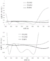
The electrically conductive coating according to the invention is designed, in particular, by selecting the materials and thicknesses of the individual layers and forming the dielectric layer sequence such that the coated composite glass pane has a reflectivity for p-polarized radiation of at least 10% over the entire spectral range from 450nm to 650 nm. This means that in the spectral range from 450nm to 650 nm no reflectivity of less than 10% occurs at any location. Thereby producing a sufficiently intense projected image. The reflectivity for p-polarized radiation is preferably at least 10% over the entire spectral range from 450nm to 700nm, particularly preferably over the entire spectral range from 450nm to 800 nm.
The reflectivity describes the proportion of all incident radiation that is reflected. It is given in% or as a unitless number from 0 to 1 (normalized based on incident radiation) based on 100% incident radiation. It forms a reflectance spectrum plotted against wavelength.
In an advantageous embodiment, the composite glass pane with the electrically conductive coating has a reflectivity for p-polarized radiation of at least 12%, preferably at least 13%, over the entire spectral range from 450nm to 650 nm. The reflectivity for p-polarized radiation is, for example, 10% to 20%, preferably 12% to 17%, in particular 13% to 15%, over the entire spectral range from 450nm to 650 nm. A reflectivity in this range can be achieved without problems with the coating according to the invention and is sufficiently high to produce a HUD projection of strong intensity.
The average value of the reflectivity for p-polarized radiation is preferably 10% to 20%, preferably 12% to 17%, in particular 13% to 15%, over the entire spectral range from 450nm to 650 nm. In order to achieve a display of the projector image that is as color neutral as possible, the reflection spectrum should be as smooth as possible and not have significant local minima and maxima. In the spectral range from 450nm to 650 nm, in a preferred embodiment the difference between the maximum occurring reflectivity and the mean value of the reflectivity and the difference between the minimum occurring reflectivity and the mean value of the reflectivity (based on 100% of the incident radiation) should be up to 5%, particularly preferably up to 3%, very particularly preferably up to 1%.
In the context of the present invention, the description of the reflectivity for p-polarized radiation relates to the reflectivity measured with an incidence angle of 65 ° with respect to the surface normal on the interior space side. The data on the reflectivity or on the reflection spectrum relate to reflection measurements with a light source which radiates uniformly with 100% normalized radiation intensity in the observed spectral range.
The projector is disposed on the inner space side of the composite glass plate, and irradiates the composite glass plate through the surface on the inner space side of the inner glass plate. Which is directed at the HUD region and illuminates the region to produce HUD projections. According to the invention, the radiation of the projector is p-polarized, preferably substantially pure p-polarized-p-polarized radiation proportion is therefore 100% or deviates therefrom only insignificantly. This produces a particularly intense HUD image and ghost images can be avoided. The data of the polarization direction relate to the plane of incidence of the radiation on the composite glass pane. Radiation whose electric field oscillates in the plane of incidence is referred to by p-polarized radiation. Radiation whose electric field oscillates perpendicular to the plane of incidence is referred to as s-polarized radiation. The plane of incidence is defined by the vector of incidence and the surface normal of the composite glass sheet in the geometric center of the HUD region.
The projector radiation preferably strikes the composite glass pane at an angle of incidence of 45 ° to 70 °, in particular 60 ° to 70 °. In an advantageous embodiment, the angle of incidence deviates from the brewster angle by at most 10 °. The p-polarized radiation is then only insignificantly reflected at the surface of the composite glass plate, so no ghost images are produced. The incident angle is an angle between an incident vector of the projector radiation and a surface normal of the internal space side in the geometric center of the HUD region (i.e., a surface normal on the outer surface of the internal space side of the composite glass plate). In the case of soda-lime glass, which is generally used for window panes, the brewster angle of the air-glass transition is 57.2 °. Ideally, the angle of incidence should be as close as possible to the brewster angle. However, for example, an angle of incidence of 65 ° can also be used, which is customary for HUD projection devices, can be realized in a vehicle without problems and deviates from the brewster angle only to a slight extent, so that the reflection of p-polarized radiation increases only insignificantly.
Since the reflection of the projector radiation is substantially performed on the reflective coating and not on the outer surfaces of the glass sheets, there is no need to arrange the outer surfaces of the glass sheets at an angle to each other in order to avoid ghost images. Thus, the outer surfaces of the composite glass sheets are preferably arranged substantially parallel to each other. The thermoplastic intermediate layer preferably does not form a wedge shape for this purpose, but rather has a substantially constant thickness, in particular also in the vertical direction between the upper edge and the lower edge of the composite glass pane, as do the inner glass pane and the outer glass pane. In contrast, the wedge-shaped intermediate layer has a variable thickness, in particular an increasing thickness, in the vertical direction running between the upper and lower edges of the composite glass pane. The intermediate layer is typically composed of at least one thermoplastic film. The production of composite glass panes is more advantageous because standard films are significantly more cost-effective than wedge-shaped films.
According to the invention, the conductive coating comprises at least three conductive layers, wherein the sum of the thicknesses of all conductive layers is at most 30nm. In a preferred embodiment, the sum of the thicknesses of all conductive layers is from 15nm to 30nm, preferably from 20nm to 25 nm. The thickness or layer thickness relates within the scope of the invention to a geometric thickness, not for example an optical thickness, which is obtained as the product of the refractive index and the geometric thickness. This is particularly advantageous in terms of cost savings and is able to meet the requirements for reflection characteristics and other optical properties. In a particularly advantageous embodiment, the number of conductive layers is exactly three. In order to achieve the required coating specifications, a more complex layer structure is in principle not required. With three conductive layers and a corresponding number of dielectric layers or layer sequences, sufficient freedom is provided for optimizing the coating with regard to transmission and reflection properties and coloring.
According to the invention, the conductive layers, in particular all conductive layers, have a thickness of 5nm to 10nm, particularly preferably 7nm to 8 nm. Layer thicknesses within the ranges given are particularly suitable for achieving the desired coating specifications. In particular, the conductive layer is sufficiently thick so as not to result in the increase in visible light absorption that surprisingly occurs when the conductive layer is too thin.
The electrical conductivity of the coating is produced by the functional conductive layer. By distributing the entire electrically conductive material over a plurality of mutually separate layers, the layers can each be designed thinner, thereby increasing the transparency of the coating. Each conductive layer preferably contains at least one metal or metal alloy, for example silver, aluminum, copper or gold, and is particularly preferably formed on the basis of a metal or metal alloy, that is to say essentially consists of a metal or metal alloy, apart from possible dopants or impurities. Silver or an alloy containing silver is preferably used. In an advantageous embodiment, the electrically conductive layer comprises at least 90% by weight of silver, preferably at least 99% by weight of silver, particularly preferably at least 99.9% by weight of silver.
According to the invention, a dielectric layer or layer sequence is arranged between the conductive layers and below the lowermost conductive layer and above the uppermost conductive layer. Each dielectric layer or layer sequence has at least one antireflection layer. The antireflection layer reduces the reflection of visible light and thus increases the transparency of the coated glass sheet. The antireflective layer comprises, for example, silicon nitride (SiN), a silicon-metal-mixed nitride, such as zirconium silicon nitride (SiZrN), aluminum nitride (AlN) or tin oxide (SnO). Particularly preferred here are silicon-metal-mixed nitrides. The antireflection layer can furthermore have dopants. The layer thickness of the individual antireflection layers is preferably from 10nm to 100nm, in particular from 20nm to 80nm.
The antireflection layer can in turn be divided into at least two sublayers, in particular a dielectric layer having a refractive index of less than 2.1 and an optically highly refractive layer having a refractive index of greater than or equal to 2.1. In principle, the order of the two sublayers can be chosen arbitrarily, wherein an optically highly refractive layer is preferably arranged above the dielectric layer, which is particularly advantageous in terms of surface resistance. The thickness of the optical high refractive layer is preferably 25 to 75% of the total thickness of the antireflection layer. The optically high refractive layer having a refractive index of 2.1 or more contains, for example, mnO, WO 3 、Nb 2 O 5 、Bi 2 O 3 、TiO 2 、Zr 3 N 4 And/or AlN, preferably a silicon-metal-mixed nitride, such as a silicon-aluminum-mixed nitride, a silicon-hafnium-mixed nitride or a silicon-titanium-mixed nitride, particularly preferably a silicon-zirconium-mixed nitride (SiZrN). The dielectric layer with a refractive index of less than 2.1 preferably comprises at least one oxide, for example tin oxide, and/or a nitride, particularly preferably silicon nitride.
In an advantageous embodiment, one or more dielectric layer sequences have a first matching layer, preferably each dielectric layer sequence arranged below the electrically conductive layer has a first matching layer. The first matching layer is preferably arranged above the antireflection layer. The first matching layer is preferably arranged directly below the conductive layer such that it directly contacts the conductive layer. This is particularly advantageous in terms of crystallinity of the conductive layer.
In an advantageous embodiment, one or more of the dielectric layer sequences has a smoothing layer, preferably each dielectric layer sequence arranged between two electrically conductive layers has a smoothing layer. The smoothing layer is arranged below one of the first matching layers, preferably between the antireflection layer and the first matching layer, if such a first matching layer is present. The smoothing layer is particularly preferably in direct contact with the first matching layer. The smoothing layer optimizes, in particular smoothes, the surface for the conductive layer applied immediately above. The conductive layer deposited on the smoother surface has a higher transmittance, while having a lower surface resistance. The layer thickness of the smoothing layer is preferably from 3nm to 20nm, particularly preferably from 4nm to 12nm, very particularly preferably from 5nm to 10nm, for example about 7nm. The smoothing layer preferably has a refractive index of less than 2.2.
The smoothing layer preferably contains at least one amorphous oxide. The oxide may be amorphous or partially amorphous (and thus partially crystalline), but not fully crystalline. The amorphous smoothing layer has a small roughness and thus forms a smooth surface which is advantageous for a layer to be applied over the smoothing layer. The amorphous smoothing layer further results in an improved surface structure of the layer deposited directly above the smoothing layer, which is preferably the first matching layer. The smoothing layer may comprise, for example, at least one oxide of one or more of the following elements: tin, silicon, titanium, zirconium, hafnium, zinc, gallium, and indium. The smoothing layer particularly preferably comprises an amorphous mixed oxide. The smoothing layer very particularly preferably comprises a tin-zinc mixed oxide (ZnSnO). The mixed oxide may have a dopant. The smoothing layer may comprise, for example, antimony-doped tin-zinc-mixed oxide. The mixed oxide preferably has a substoichiometric oxygen content. The tin proportion is preferably from 10 to 40% by weight, particularly preferably from 12 to 35% by weight.
In an advantageous embodiment, one or more dielectric layer sequences have a second matching layer, preferably each dielectric layer sequence arranged above the electrically conductive layer has a second matching layer. The second matching layer is preferably arranged below the antireflection layer.
The first and second matching layers improve the surface resistance of the coating. The first matching layer and/or the second matching layer preferably contain zinc oxide ZnO 1-δ Wherein delta is more than or equal to 0 and less than or equal to 0.01. The first matching layer and/or the second matching layer further preferably comprise a dopant. The first matching layer and/or the second matching layer mayTo contain, for example, aluminum-doped zinc oxide (ZnO: al). The zinc oxide is preferably deposited sub-stoichiometrically with respect to the oxygen to avoid excess oxygen from reacting with the silver-containing layer. The layer thicknesses of the first matching layer and the second matching layer are preferably from 3nm to 20nm, particularly preferably from 50nm to 15nm, very particularly preferably from 8nm to 12nm, in particular about 10nm.
In an advantageous embodiment, the conductive coating comprises one or more barrier layers. At least one, particularly preferably at least one, barrier layer is assigned to at least one, particularly preferably to each, electrically conductive layer. The barrier layer is in direct contact with the conductive layer and is disposed immediately above or immediately below the conductive layer. I.e. no further layers are arranged between the conductive layer and the barrier layer. It is also possible to arrange one barrier layer each immediately above the conductive layer or immediately below the conductive layer. The barrier layer preferably comprises niobium, titanium, nickel, chromium and/or alloys thereof, particularly preferably a nickel-chromium alloy. The layer thickness of the barrier layer is preferably from 0.1nm to 2nm, particularly preferably from 0.1nm to 1nm. The barrier layer immediately below the conductive layer serves in particular to stabilize the conductive layer during the temperature treatment and to improve the optical quality of the conductive coating. The barrier layer immediately above the conductive layer prevents the sensitive conductive layer from coming into contact with the oxidizing reactive atmosphere during deposition of subsequent layers (e.g., the second matching layer) by reactive cathode sputtering.
If the first layer is arranged above the second layer, this means in the sense of the present invention that the first layer is arranged further away from the substrate on which the coating is applied than the second layer. If the first layer is arranged below the second layer, this means in the sense of the present invention that the second layer is arranged further away from the substrate than the first layer. If the first layer is arranged above or below the second layer, this does not necessarily mean in the sense of the present invention that the first and second layers are in direct contact with each other. One or more further layers may be arranged between the first layer and the second layer, as long as this is not explicitly excluded. The values given for the refractive index are measured at a wavelength of 550 nm.
In one advantageous embodiment, a dielectric layer sequence is arranged between two electrically conductive layers (21) in each case, said dielectric layer sequence comprising:
an anti-reflection layer (22) based on silicon nitride (SiN), a silicon-metal-mixed nitride such as zirconium silicon nitride (SiZrN), aluminum nitride (AlN) or tin oxide (SnO), preferably on a silicon-metal-mixed nitride,
-a smoothing layer (23) based on oxides of one or more of the following elements: tin, silicon, titanium, zirconium, hafnium, zinc, gallium and indium,
-a first and a second matching layer (24, 25) based on zinc oxide, and
-an optional barrier layer (26) based on niobium, titanium, nickel, chromium and/or alloys thereof. The order of the layers is not to be assumed here. An antireflection layer and a matching layer based on the above-mentioned preferred materials are preferably arranged below the lowermost conductive layer and above the uppermost conductive layer. The preferred ranges already mentioned apply to the layer thicknesses of the individual layers.
The electrically conductive coating having the reflective properties according to the invention can in principle be realized in various ways, preferably using the above-mentioned layers, so that the invention is not limited to a specific layer sequence. In the following, a particularly preferred embodiment of the coating is given, with which particularly good results are achieved, in particular at typical radiation incidence angles of about 65 °.
The conductive coating comprises at least three, in particular exactly three, conductive layers, preferably based on silver, wherein each conductive layer has a thickness of 5nm to 10nm, in particular 7nm to 8 nm. Hereinafter, the conductive layer is numbered starting from the substrate on which the coating is deposited. The sequence of dielectric layers below the lowermost conductive layer, above the uppermost conductive layer and between the conductive layers comprises in each case one antireflection layer, preferably based on silicon-metal-mixed nitrides such as zirconium silicon nitride or hafnium silicon nitride. The antireflective layer under the first conductive layer has a thickness of 15nm to 25nm, particularly preferably 20nm to 24 nm. The antireflective layer between the first and second conductive layers has a thickness of 25nm to 40nm, preferably 30nm to 35 nm. The antireflective layer between the second and third conductive layers has a thickness of 70nm to 90nm, preferably 75nm to 80nm. The antireflection layer over the third conductive layer has a thickness of 35nm to 45nm, preferably 37nm to 42 nm.
A very particularly preferred embodiment of the electrically conductive coating comprises, or consists of, starting from the substrate, the following layer sequence:
an antireflection layer having a thickness of from 15nm to 25nm, preferably from 20nm to 24nm, preferably based on a silicon-metal-mixed nitride such as zirconium silicon nitride or hafnium silicon nitride,
a first matching layer having a thickness of 5nm to 15nm, preferably 8nm to 12nm, preferably based on zinc oxide,
-an electrically conductive layer, based on silver, having a thickness of 6 to 9 nm,
-an optional barrier layer having a thickness of 0.1nm to 0.5 nm, preferably based on NiCr,
a second matching layer having a thickness of 5 to 15nm, preferably 8 to 12nm, preferably based on zinc oxide,
an antireflective layer having a thickness of 25nm to 40nm, preferably 30nm to 35nm, preferably based on a silicon-metal-mixed nitride such as zirconium silicon nitride or hafnium silicon nitride,
a smoothing layer having a thickness of 5nm to 10nm, preferably based on a tin-zinc-mixed oxide,
a first matching layer having a thickness of 5nm to 15nm, preferably 8nm to 12nm, preferably based on zinc oxide,
-a conductive layer based on silver having a thickness of 6 to 10nm,
-an optional barrier layer having a thickness of 0.1nm to 0.5 nm, preferably based on NiCr,
a second matching layer having a thickness of 5 to 15nm, preferably 8 to 12nm, preferably based on zinc oxide,
an antireflection layer having a thickness of from 70nm to 90nm, preferably from 75nm to 80nm, preferably based on a silicon-metal-mixed nitride such as zirconium silicon nitride or hafnium silicon nitride,
a smoothing layer having a thickness of 5nm to 10nm, preferably based on a tin-zinc-mixed oxide,
a first matching layer having a thickness of 5nm to 15nm, preferably 8nm to 12nm, preferably based on zinc oxide,
-a conductive layer based on silver having a thickness of 6 to 9 nm,
-an optional barrier layer having a thickness of 0.1nm to 0.5 nm, preferably based on NiCr,
a second matching layer having a thickness of 5 to 15nm, preferably 8 to 12nm, preferably based on zinc oxide,
an antireflective layer having a thickness of 35nm to 45nm, preferably 37nm to 42nm, preferably based on a silicon-metal-mixed nitride such as zirconium silicon nitride or hafnium silicon nitride.
A particularly preferred embodiment of the electrically conductive coating comprises, or consists of, the following layer sequence starting from the substrate:
an antireflection layer based on a silicon-metal-mixed nitride, such as zirconium silicon nitride or hafnium silicon nitride, having a thickness of 21 nm to 23 nm,
a first matching layer, based on zinc oxide, having a thickness of 6 to 11 nm,
-a conductive layer, based on silver, having a thickness of 6.5 nm to 8.5 nm,
-an optional barrier layer based on NiCr having a thickness of 0.1 to 0.3 nm,
a second matching layer, based on zinc oxide, having a thickness of 9 nm to 11 nm,
an antireflection layer based on a silicon-metal-mixed nitride, such as zirconium silicon nitride or hafnium silicon nitride, having a thickness of 32 nm to 34 nm,
a smoothing layer, based on a tin-zinc mixed oxide, having a thickness of 6 nm to 8nm,
a first matching layer, based on zinc oxide, having a thickness of 9 to 11 nm,
-an electrically conductive layer, based on silver, having a thickness of 7 to 9 nm,
-an optional barrier layer based on NiCr having a thickness of 0.1nm to 0.3 nm,
a second matching layer, based on zinc oxide, having a thickness of 9 nm to 11 nm,
an antireflection layer based on a silicon-metal-mixed nitride, such as zirconium silicon nitride or hafnium silicon nitride, having a thickness of 76.5 nm to 78.5 nm,
a smoothing layer based on a tin-zinc mixed oxide having a thickness of 6 nm to 8nm,
a first matching layer, based on zinc oxide, having a thickness of 9 to 11 nm,
-an electrically conductive layer, based on silver, having a thickness of 6.5 nm to 8.5 nm,
-an optional barrier layer based on NiCr having a thickness of 0.1 to 0.3 nm,
a second matching layer, based on zinc oxide, having a thickness of 9 nm to 11 nm,
an anti-reflective layer based on a silicon-metal-mixed nitride such as zirconium silicon nitride or hafnium silicon nitride, having a thickness of 38 nm to 40 nm.
If a layer is formed on the basis of a material, the majority of the layer consists of this material, except possibly for impurities or dopants.
The surface resistance of the conductive coating is preferably 1 To 2
To 2 . Such a surface resistance can be achieved without problems with the coating according to the invention while ensuring the desired optical properties.
In one embodiment of the invention, the electrically conductive coating is connected to a voltage source so as to conduct an electric current through the coating, whereby the coating heats up. Thus, the composite glass sheet can be heated. In particular, vehicle-mounted voltages that are customary in the vehicle sector, for example 12V to 14V, are considered as voltages. It has been shown that good heating power is achieved in particular with the coating according to the invention when the coating according to the invention is connected to a voltage source of 40V to 50V, for example 42V or 48V, as is customary in particular in electric vehicles. Thus, 1500W/m can be realized 2 To 5000W/m 2 In particular 2200W/m 2 To 3000W/m 2 Suitable for rapidly freeing the composite glass sheet from condensed moisture or ice. For connection to a voltage source, the coating is preferablyOptionally, current busbars (busbars) are provided which can be connected to the poles of the voltage source in order to introduce current into the coating over as large a portion as possible of the width of the glass pane. The current busbars may be formed, for example, as printed and baked conductors, typically in the form of a baked screen-printed paste with glass frit and silver particles. Alternatively, however, strips of electrically conductive film can also be used as bus conductors, which are placed or glued on a coating, for example copper foil or aluminum foil. Typically, two bus conductors are positioned near two mutually opposing lateral edges (e.g., an upper edge and a lower edge) of the composite glass pane.
The outer and inner glass panes are preferably made of glass, in particular soda-lime glass, as is customary for window panes. However, these glass plates can in principle also be made of other types of glass (e.g. borosilicate glass, quartz glass, aluminosilicate glass) or transparent plastics (e.g. polymethyl methacrylate or polycarbonate). The thickness of the outer and inner glass sheets can vary widely. Preference is given to using glass plates having a thickness of from 0.8 mm to 5 mm, preferably from 1.4 mm to 2.5 mm, for example glass plates having a standard thickness of 1.6 mm or 2.1 mm.
The outer glass pane, the inner glass pane and the thermoplastic interlayer may be clear and colorless, but may also be colored or tinted. In a preferred embodiment, the total transmission through the composite glass is greater than 70%. The term total transmission refers to the method for detecting the light transmission of automotive glazing as determined by ECE-R43, appendix 3, § 9.1. The outer and inner glass sheets may be non-prestressed, partially prestressed or prestressed independently of one another. If at least one of the glass sheets should be prestressed, it may be thermally or chemically prestressed. It must be ensured that the conductive coating does not reduce the total transmission too strongly.
In addition to total transmission, the composite glass sheet should also have an outside reflection color that is as neutral as possible to provide aesthetic satisfaction to the user. The reflected color is typically characterized in La × b color space using viewing angles of light sources D65 and 10 °, at incident angles of 8 ° and 60 ° with respect to the lateral side normal. It has been shown that composite glass panels without excessive color deviation can be achieved with the coating according to the invention. At an angle of incidence of 8 °, the value a is preferably-4 to 0 and the value b is-13 to-3. At an angle of incidence of 60 °, the value a is preferably-2 to 2, and the value b is-9 to 1. Such glass sheets have sufficiently insignificant color deviations to become accepted by the automotive industry.
The composite glass sheet is preferably curved in one or more spatial directions, as is common for automotive glass, with a typical radius of curvature of about 10 cm to about 40 m. However, the composite glass sheet may also be planar, for example when provided as a glass sheet for a bus, train or tractor.
The thermoplastic interlayer comprises at least one thermoplastic polymer, preferably Ethylene Vinyl Acetate (EVA), polyvinyl butyral (PVB) or Polyurethane (PU), or mixtures or copolymers or derivatives thereof, particularly preferably PVB. The intermediate layer is typically formed from a thermoplastic film. The thickness of the intermediate layer is preferably from 0.2 mm to 2 mm, particularly preferably from 0.3 mm to 1 mm.
The composite glass sheet can be manufactured by methods known per se. The outer and inner glass sheets are laminated to each other via an interlayer, for example, by hot press, vacuum bag, vacuum ring, calendering, vacuum laminator, or combinations thereof. The connection of the outer glass pane and the inner glass pane is usually carried out here under the influence of heat, vacuum and/or pressure.
The electrically conductive coating is preferably applied to the inner glass plate by Physical Vapor Deposition (PVD), particularly preferably by cathode sputtering ("sputtering"), very particularly preferably by magnetic field-assisted cathode sputtering. The coating is preferably applied to the glass sheets prior to lamination. Instead of applying the electrically conductive coating to the surface of the glass pane, it is in principle also possible to provide it on a carrier film which is arranged in the intermediate layer.
If the composite glass pane should be bent, the outer glass pane and the inner glass pane are preferably subjected to a bending process before lamination and preferably after a possible coating process. Preferably, the outer glass pane and the inner glass pane are jointly (i.e. simultaneously and by the same tool) identically bent, since the shapes of the glass panes are thereby optimally matched to one another for the subsequent lamination. Typical temperatures for the glass bending process are, for example, 500 ℃ to 700 ℃. This temperature treatment also improves the transparency of the conductive coating and reduces the surface resistance.
The invention also relates to the use of a composite pane formed according to the invention as a projection surface for a projection device for a head-up display, wherein a projector is directed at the HUD region, the radiation of which is p-polarized. The preferred embodiments described above are accordingly suitable for this purpose.
The invention also comprises the use of the projection device according to the invention as a HUD in a motor vehicle, in particular a passenger car or a lorry.
The invention is explained in more detail below with the aid of figures and examples. The figures are schematic and not drawn to scale. The drawings are not intended to limit the invention in any way.
Displaying:
figure 1 shows a top view of a composite glass sheet of a generic (gattonsgem 228beta) projection arrangement,
figure 2 shows a cross-section through a general projection device,
figure 3 shows a cross-section through a composite glass sheet of a projection device according to the invention,
FIG. 4 shows a cross-section through a conductive coating according to the invention, an
Fig. 5 shows the reflection spectra for p-polarized radiation of a composite glass pane having a conductive coating according to the invention and of two comparative examples.
Fig. 1 and 2 each show a detail of a generic projection device for HUDs. The projection device comprises a composite glass pane 10, in particular a windscreen of a passenger car. Further, the projection apparatus includes a projector 4, which is directed to the region B of the composite glass sheet 10. In the region B, which is usually referred to as the HUD region, an image can be generated by the projector 4, which image is perceived by the observer 5 (vehicle driver) as a virtual image on the side of the composite pane 10 remote from him, when the eyes of the observer 5 (vehicle driver) are located within the so-called eye-box E.
The composite glass pane 10 consists of an outer glass pane 1 and an inner glass pane 2, which are connected to one another by means of a thermoplastic interlayer 3. The lower edge U thereof is arranged downwards towards the engine of the passenger car and the upper edge O thereof is arranged upwards towards the top. The outer pane 1 is oriented towards the outside environment in the installed position, and the inner pane 2 is oriented towards the vehicle interior.
Figure 3 illustrates one embodiment of a composite glass sheet 10 formed in accordance with the present invention. The outer glass pane 1 has an outer side surface I facing the external environment in the mounted position and an inner space side surface II facing the inner space in the mounted position. Likewise, the inner glass pane 2 has an outer side surface III facing the outside environment in the mounted position and an inner space side surface IV facing the inner space in the mounted position. The outer glass plate 1 and the inner glass plate 2 are made of soda lime glass, for example. The outer glass plate 1 has a thickness of, for example, 2.1 mm and the inner glass plate 2 has a thickness of, for example, 1.6 mm. The interlayer 3 is formed, for example, from a PVB film having a thickness of 0.76 mm. The PVB film has a substantially constant thickness, except for possible surface roughness as is conventional in the art.
The outer side surface III of the inner glass pane 2 has an electrically conductive coating 20 according to the invention, which is provided as a reflective surface for the projector radiation and additionally, for example, as an IR-reflecting coating or as a heatable coating.
According to the invention, the radiation of the projector 4 is p-polarized, in particular substantially pure p-polarized. Since projector 4 illuminates composite glass sheet 10 at an angle of incidence of approximately 65 ° near the brewster angle, the projector's radiation is only insignificantly reflected on the outer surfaces I, IV of composite glass sheet 10. In contrast, the conductive coating 20 according to the present invention is optimized for reflection of p-polarized radiation. It acts as a reflective surface for the radiation of the projector 4 used to generate the HUD projection.
Fig. 4 shows a layer sequence of the electrically conductive coating 20 according to the invention. The coating 20 comprises three electrically conductive layers 21 (21.1, 21.2, 21.3). Each conductive layer 21 is arranged between two of a total of four antireflection layers 22 (22.1, 22.2, 22.3, 22.4). The coating 20 furthermore comprises two smoothing layers 23 (23.2, 23.3), three first matching layers 24 (24.1, 24.2, 24.3), three second matching layers 25 (25.2, 25.3, 25.4) and three barrier layers 26 (26.1, 26.2, 26.3).
The layer sequence is schematically known from the figures. Furthermore, the layer sequence of the composite glass pane 10 with the coating 20 on the outer side surface III of the inner glass pane 2 is shown in table 1 together with the material and layer thickness of the individual layers (example). Table 1 furthermore shows the layer sequence of two comparative examples with four conductive coatings 21 each. Comparative example 2 is a conductive coating which is already in use at present, while comparative example 1 is a coating having a layer thickness of the conductive layer 21 which is significantly smaller than that. The materials of the layers may have dopants not given in the table. Thus, for example, a SnZnO based layer can be doped with antimony, while a ZnO, siN or SiZrN based layer can be doped with aluminum.
A comparison of the examples with comparative example 2 clearly shows that the coating 20 according to the invention is distinguished in particular by a significantly thinner conductive layer 21. Thus, the coating 20 according to the invention can be deposited more cost-effectively. However, the electrical conductivity is still sufficiently high to use the coating 20 according to the invention as a heatable coating, in particular in combination with a supply voltage of 40V to 50V. The desired reflective properties, the desired sheet resistance and other optical properties are set by the construction of suitable dielectric layers.
Comparative example 1 has the total thickness of all the conductive layers 21 similar to the example. However, this is distributed over more conductive layers, and thus the thickness of each layer is less than in the embodiment. As has surprisingly been shown, too small a layer thickness leads to an increase in the light absorption. This can be avoided with the layer structure according to the invention.
In the embodiment according to the present invention, the antireflection layer 22 is formed as a single layer based on zirconium silicon nitride. In the comparative example, the anti-reflection layer was partially divided into two single layers: a silicon nitride based layer and a zirconium silicon nitride based layer. Such division of the antireflection layer can contribute to a reduction in the surface resistance and can in principle also be used within the scope of the invention. However, in this embodiment, it is not necessary to achieve the required specifications for the composite glass sheet.
TABLE 1

Fig. 5 shows the reflection spectra for p-polarized radiation of a composite glass pane 10 according to the comparative example with a conventional conductive coating 20 and a conductive coating 20 according to the invention according to the example (see table 1). The spectra were measured at an angle of incidence of 65 ° on the interior space side, thus simulating the reflection characteristics of a HUD projector. The two illustrations of the figures differ only in the scale of the ordinate.
The examples according to the invention have, on the one hand, a higher average reflection in the relevant spectral range and, on the other hand, are significantly smoother than the comparative example, relative to comparative example 2. This enables a more intense and more color neutral display of the HUD projection.
Comparative example 1 has similar reflectance and similar smoothness as the example in the relevant spectral range. Therefore, comparative example 1 is also suitable for manufacturing HUD projection using p-polarized light. However, the thin silver layer of comparative example 1 surprisingly reduces the light transmission through the composite glass sheet, which may be critical in the case of windshields.
For the examples, the reflectance was at least 13% over the entire spectral range from 450nm to 650 nm, for comparative example 1 at least 15%, and for comparative example 2 even values of only 3% occurred. For an embodiment, the difference between the maximum occurring reflectivity and the average value of the reflectivity is 0% and the difference between the minimum occurring reflectivity and the average value of the reflectivity is 1% over the spectral range of 450nm to 650 nm. For comparative example 1, corresponding values are 1% and 0%, and for comparative example 2, corresponding values are 7% and 6%.
Some optical values of the composite glass sheet according to the invention (examples according to table 1) and of the comparative example (comparative example 1 according to table 1) are given in table 2, which are familiar to the person skilled in the art and are generally used for characterizing vehicle glass sheets. Where RL denotes the integrated light reflectivity and TL denotes the integrated light transmission (according to ISO 9050). The light source used is given in terms of data for RL or TL, where a denotes light source a and the HUD denotes a HUD projector with radiation wavelengths of 473 nm, 550nm and 630 nm (RGB). The angle data according to the light type gives the angle of incidence of the radiation with respect to the outside surface normal. An angle of incidence of less than 90 ° therefore indicates radiation on the outside, and an angle of incidence of more than 90 ° indicates radiation on the side of the interior space. The given incidence angle of 115 ° corresponds to an incidence angle of 65 ° (= 180 ° -115 °) relative to the surface normal of the interior space side and simulates illumination with a projector according to the invention. In each case, the reflection values are assigned color values a and b in the color space L a b, followed by the data of the light source used (light source D65 and HUD projector) and the data of the viewing angle (the angle at which the light beam impinges on the retina in the eye).
TTS ISO 13837 represents total incident solar energy measured according to ISO 13837 and is a measure of thermal comfort.
The integrated reflectance and color values are similar for both glass plates. The reflection on the inner space side of the p-polarized HUD projector radiation is sufficiently high to ensure an intense HUD projection. At the same time, the reflective color of the outer side is relatively neutral, so that the composite glass sheet does not have unpleasant color deviations. However, embodiments according to the present invention have significantly higher light transmission due to the thicker silver layer, which is advantageous for applications as windshields.
The surface resistance of the coating 20 was 1.5 Thus, approximately 2300W/m can be achieved with a supply voltage of, for example, 42V and a typical windshield height (spacing of the busbars) 2 The heating power of (2).
TABLE 2
| Examples | Comparative example 1 | |
| RL A 8° / % | 16.8 | 16.9 |
| a* (D65 / 10°) | -1.9 | -2.0 |
| b* (D65 / 10°) | -9.5 | -5.0 |
| RL A 60° / % | 21.8 | 22.3 |
| a* (D65 / 10°) | 0.7 | 1.1 |
| b* (D65 / 10°) | -5.1 | -2.6 |
| RL HUD p-pol. 115° / % | 14.2 | 15.2 |
| a* (HUD / 10°) | -0.8 | -1.0 |
| b* (HUD / 10°) | -0.2 | 0.2 |
| TL A 0° / % | 73.0 | 71.6 |
| TTS ISO 13837 / % | 56.0 | 53.4 |
List of reference numerals:
(10) Composite glass plate
(1) Outer glass plate
(2) Inner glass plate
(3) Thermoplastic interlayer
(4) Projector with a light source
(5) Observer/vehicle driver
(20) Conductive coating
(21) Conductive layer
(21.1), (21.2), (21.3), (21.4) 1, 2, 3, 4. Conductive layer
(22) Antireflection layer
(22.1), (22.2), (22.3), (22.4), (22.5) 1, 2, 3, 4, 5. Antireflection layer
(23) Smoothing layer
(23.2), (23.3), (23.4) 1, 2, 3. Smoothing layer
(24) First matching layer
(24.1), (24.2), (24.3), (24.4) 1, 2, 3, 4. First matching layer
(25) Second matching layer
(25.2), (25.3), (25.4), (25.5) 1, 2, 3, 4. Second matching layer
(26) Barrier layer
(26.1), (26.2), (26.3), (26.4) 1, 2, 3, 4. Barrier layer
Upper edge of (O) composite glass plate 10
Lower edge of (U) composite glass pane 10
(B) HUD region of composite glass pane 10
(E) Eye box
(I) The outer surface of the outer glass pane 1 remote from the intermediate layer 3
(II) inner space-side surface of outer glass pane 1 facing interlayer 3
(III) outer surface of the inner glass pane 2 facing the intermediate layer 3
(IV) the inner space-side surface of the inner glass plate 2 remote from the interlayer 3.
Claims (21)
1. Projection device for a head-up display, HUD, comprising at least
-a composite glass pane (10) comprising an outer glass pane (1) and an inner glass pane (2) which are connected to each other by a thermoplastic interlayer (3), said composite glass pane having a HUD region (B);
-an electrically conductive coating (20) on the surface (II, III) of the outer glass pane (1) or the inner glass pane (2) facing the intermediate layer (3) or within the intermediate layer (3); and
-a projector (4) aimed at the HUD region (B);
wherein the radiation of the projector (4) is p-polarized,
wherein the composite glass pane (10) with the electrically conductive coating (20) has a reflectivity for p-polarized radiation of at least 10% over the entire spectral range from 450nm to 650 nm, and
wherein the electrically conductive coating (20) comprises three electrically conductive layers (21), which are each arranged between two dielectric layers or layer sequences,
wherein the sum of the thicknesses of all conductive layers (21) is at most 30nm, and wherein the conductive layers (21) have a thickness of 5nm to 10nm,
wherein each dielectric layer sequence comprises an antireflection layer (22), and wherein
-the antireflection layer (22.1) below the first conductive layer (21.1) has a thickness of 15 to 25nm,
-the antireflection layer (22.2) between the first conductive layer (21.1) and the second conductive layer (21.2) has a thickness of 25nm to 40nm,
-the antireflection layer (22.3) between the second conductive layer (21.2) and the third conductive layer (21.3) has a thickness of 70nm to 90nm,
-the antireflection layer (22.4) above the third conductive layer (21.3) has a thickness of 35 to 45 nm.
2. A projection device according to claim 1, wherein the composite glass sheet (10) with the conductive coating (20) has a reflectivity for p-polarized radiation of at least 12% over the entire spectral range from 450nm to 650 nm.
3. A projection device according to claim 1 or 2, wherein the difference between the maximum occurring reflectivity and the average value of the reflectivity and the difference between the minimum occurring reflectivity and the average value of the reflectivity is at most 5% for p-polarized radiation in the spectral range of 450nm to 650 nm.
4. A projection device according to claim 3, wherein the difference between the maximum occurring reflectivity and the average value of the reflectivities and the difference between the minimum occurring reflectivity and the average value of the reflectivities is at most 3% for p-polarized radiation in the spectral range of 450nm to 650 nm.
5. A projection arrangement according to claim 3, wherein the difference between the maximum occurring reflectivity and the average value of the reflectivity and the difference between the minimum occurring reflectivity and the average value of the reflectivity is at most 1% for p-polarized radiation in the spectral range of 450nm to 650 nm.
6. A projection device according to claim 1 or 2, wherein the sum of the thicknesses of all conductive layers (21) is from 15nm to 30nm.
7. A projection device according to claim 1 or 2, wherein the sum of the thicknesses of all conductive layers (21) is from 20nm to 25 nm.
8. A projection device according to claim 1 or 2, wherein the conductive layer (21) has a thickness of 7nm to 8 nm.
9. A projection device according to claim 1 or 2, wherein the conductive layer (21) is formed on the basis of silver.
10. A projection device according to claim 1 or 2, wherein
-the antireflection layer (22.1) below the first conductive layer (21.1) has a thickness of 20 to 24nm,
-the antireflection layer (22.2) between the first conductive layer (21.1) and the second conductive layer (21.2) has a thickness of 30nm to 35nm,
-the antireflection layer (22.3) between the second conductive layer (21.2) and the third conductive layer (21.3) has a thickness of 75 to 80nm,
-the antireflection layer (22.4) above the third conductive layer (21.3) has a thickness of 37 to 42 nm.
11. Projection apparatus according to claim 10, wherein the antireflection layer (22) is formed on the basis of a silicon-metal-nitride.
12. The projection apparatus of claim 11, wherein the silicon-metal-nitride is zirconium silicon nitride or hafnium silicon nitride.
13. Projection device according to claim 1 or 2, wherein a dielectric layer sequence is arranged between two electrically conductive layers (21) each, said dielectric layer sequence comprising
-an anti-reflection layer (22) based on silicon nitride, silicon-metal-mixed nitride, aluminum nitride or tin oxide,
-a smoothing layer (23) based on oxides of one or more of the following elements: tin, silicon, titanium, zirconium, hafnium, zinc, gallium and indium,
-a first and a second matching layer (24, 25) based on zinc oxide, and
-an optional barrier layer (26) based on niobium, titanium, nickel, chromium and/or alloys thereof.
14. The projection apparatus according to claim 13, wherein the silicon-metal-mixed nitride is zirconium silicon nitride.
15. A projection device according to claim 1 or 2, wherein the conductive coating has a value of 1 To 2
To 2 The surface resistance of (1).
16. A projection device as claimed in claim 1 or 2, wherein the radiation of the projector (4) is purely p-polarized.
17. A projection device according to claim 1 or 2, wherein the outer surfaces (I, IV) of the composite glass pane (10) are arranged parallel to each other.
18. A projection device according to claim 1 or 2, wherein the radiation of the projector (4) impinges on the composite glass pane (10) at an angle of incidence of 60 ° to 70 °.
19. A projection device according to claim 1 or 2, wherein the conductive coating (20) is connected to a voltage source of 40V to 50V in order to heat the composite glass sheet.
20. Use of a projection device according to one of claims 1 to 19 as a HUD in a motor vehicle.
21. Use according to claim 20, wherein the motor vehicle is a passenger car or a truck.
Applications Claiming Priority (3)
| Application Number | Priority Date | Filing Date | Title |
|---|---|---|---|
| EP18205414.8 | 2018-11-09 | ||
| EP18205414 | 2018-11-09 | ||
| PCT/EP2019/079141 WO2020094423A1 (en) | 2018-11-09 | 2019-10-25 | Projection arrangement for a head-up display (hud) with p-polarised radiation |
Publications (2)
| Publication Number | Publication Date |
|---|---|
| CN111433022A CN111433022A (en) | 2020-07-17 |
| CN111433022B true CN111433022B (en) | 2023-01-13 |
Family
ID=64270710
Family Applications (1)
| Application Number | Title | Priority Date | Filing Date |
|---|---|---|---|
| CN201980003505.4A Active CN111433022B (en) | 2018-11-09 | 2019-10-25 | Projection device for a head-up display (HUD) using p-polarized radiation |
Country Status (11)
| Country | Link |
|---|---|
| US (1) | US20210316533A1 (en) |
| EP (1) | EP3877176B1 (en) |
| JP (1) | JP7174847B2 (en) |
| KR (1) | KR102626086B1 (en) |
| CN (1) | CN111433022B (en) |
| BR (1) | BR112021001729A2 (en) |
| MA (1) | MA54135A (en) |
| MX (1) | MX2021005432A (en) |
| PE (1) | PE20210989A1 (en) |
| RU (1) | RU2768097C1 (en) |
| WO (1) | WO2020094423A1 (en) |
Families Citing this family (16)
| Publication number | Priority date | Publication date | Assignee | Title |
|---|---|---|---|---|
| US20230228991A1 (en) * | 2020-07-20 | 2023-07-20 | Saint-Gobain Glass France | Projection arrangement for a head-up display (hud) with p-polarised radiation |
| JP2023536238A (en) | 2020-07-29 | 2023-08-24 | サン-ゴバン グラス フランス | Projection equipment for head-up displays (HUD) using p-polarized radiation |
| FR3114044B1 (en) * | 2020-09-14 | 2022-11-18 | Saint Gobain | Laminated glazing with reduced exterior light reflection and head-up display for improved visibility |
| WO2022083988A1 (en) | 2020-10-19 | 2022-04-28 | Saint-Gobain Glass France | Projection arrangement for a head-up display (hud) with p-polarized radiation |
| CN114793449A (en) | 2020-11-23 | 2022-07-26 | 法国圣戈班玻璃厂 | Projection device for a head-up display (HUD) with p-polarized radiation |
| JP2023550516A (en) | 2020-11-27 | 2023-12-01 | サン-ゴバン グラス フランス | Composite pane with solar shading coating |
| JP2023551674A (en) | 2020-11-27 | 2023-12-12 | サン-ゴバン グラス フランス | Composite pane with solar shading coating |
| WO2022157022A1 (en) * | 2021-01-19 | 2022-07-28 | Saint-Gobain Glass France | Pane having heatable sensor field |
| US20240009967A1 (en) | 2021-01-21 | 2024-01-11 | Saint-Gobain Glass France | Projection assembly for a head-up display (hud) with p-polarized radiation |
| CN113031276B (en) | 2021-03-29 | 2022-05-10 | 福耀玻璃工业集团股份有限公司 | Head-up display system |
| CN113238378B (en) | 2021-04-14 | 2022-07-19 | 福耀玻璃工业集团股份有限公司 | Head-up display system |
| CN116075491A (en) * | 2021-08-31 | 2023-05-05 | 法国圣戈班玻璃厂 | Composite glass plate for vehicles |
| CN116075416A (en) | 2021-09-03 | 2023-05-05 | 法国圣戈班玻璃厂 | Composite panel for head-up display |
| CN114349371B (en) * | 2022-01-17 | 2022-09-09 | 福耀玻璃工业集团股份有限公司 | Laminated glass and head-up display system |
| WO2023143959A1 (en) | 2022-01-25 | 2023-08-03 | Saint-Gobain Glass France | Projection assembly for a head-up display (hud) with p-polarized radiation |
| CN114935280B (en) * | 2022-04-28 | 2023-12-01 | 中北大学 | TC4/Ni/Al laminated composite material and preparation method thereof |
Citations (7)
| Publication number | Priority date | Publication date | Assignee | Title |
|---|---|---|---|---|
| CN104267499A (en) * | 2014-10-14 | 2015-01-07 | 福耀玻璃工业集团股份有限公司 | Head up display system |
| CN204143067U (en) * | 2014-10-14 | 2015-02-04 | 福耀玻璃工业集团股份有限公司 | A kind of head-up-display system |
| CN106094072A (en) * | 2016-07-29 | 2016-11-09 | 福耀玻璃工业集团股份有限公司 | A kind of display laminated glass and head-up-display system of coming back |
| CN205899060U (en) * | 2016-07-29 | 2017-01-18 | 福耀玻璃工业集团股份有限公司 | Come back and show laminated glass and new line display system |
| CN106526854A (en) * | 2016-11-15 | 2017-03-22 | 福耀玻璃工业集团股份有限公司 | Automobile head-up display system capable of carrying out electric heating |
| CN207190747U (en) * | 2017-09-14 | 2018-04-06 | 江苏华尚汽车玻璃工业有限公司 | One kind, which comes back, shows front windshield |
| DE102017102552A1 (en) * | 2017-02-09 | 2018-08-09 | CG Rail - Chinesisch-Deutsches Forschungs- und Entwicklungszentrum für Bahn- und Verkehrstechnik Dresden GmbH | Car body for a rail vehicle |
Family Cites Families (17)
| Publication number | Priority date | Publication date | Assignee | Title |
|---|---|---|---|---|
| US6734396B2 (en) | 2001-09-07 | 2004-05-11 | Centre Luxembourgeois De Recherches Pour Le Verre Et La Ceramique S.A. (C.R.V.C.) | Heatable vehicle window with different voltages in different heatable zones |
| US7158095B2 (en) * | 2003-07-17 | 2007-01-02 | Big Buddy Performance, Inc. | Visual display system for displaying virtual images onto a field of vision |
| FR2862961B1 (en) * | 2003-11-28 | 2006-02-17 | Saint Gobain | TRANSPARENT SUBSTRATE USED ALTERNATELY OR CUMULATIVELY FOR THERMAL CONTROL, ELECTROMAGNETIC SHIELDING AND HEATED GLAZING. |
| US7355796B2 (en) * | 2004-07-19 | 2008-04-08 | Colorlink, Inc. | Automobile windshield for HUD system |
| JP2008544878A (en) | 2005-05-11 | 2008-12-11 | イー・アイ・デュポン・ドウ・ヌムール・アンド・カンパニー | Polymer interlayer with wedge-shaped profile |
| US7335421B2 (en) | 2005-07-20 | 2008-02-26 | Ppg Industries Ohio, Inc. | Heatable windshield |
| JP2007223883A (en) | 2005-12-26 | 2007-09-06 | Asahi Glass Co Ltd | Laminated glass for vehicle |
| KR20090021824A (en) * | 2007-08-28 | 2009-03-04 | 엘지전자 주식회사 | Filter and display device thereof |
| ES2671174T3 (en) | 2007-12-07 | 2018-06-05 | Saint-Gobain Glass France | Curved windshield of vehicle made of laminated glass |
| KR101589854B1 (en) | 2012-01-10 | 2016-01-28 | 쌩-고벵 글래스 프랑스 | Transparent pane with electrically conductive coating |
| WO2013104438A1 (en) | 2012-01-10 | 2013-07-18 | Saint-Gobain Glass France | Transparent panel with electrically conductive coating |
| WO2013190959A1 (en) * | 2012-06-22 | 2013-12-27 | 旭硝子株式会社 | Head-up display |
| RU2518863C1 (en) * | 2012-09-14 | 2014-06-10 | Открытое акционерное общество "ЛОМО" | Optical system for projection type on-board display |
| US9121100B2 (en) * | 2012-12-14 | 2015-09-01 | Intermolecular, Inc. | Silver based conductive layer for flexible electronics |
| DE102014220189B4 (en) * | 2014-10-06 | 2023-08-17 | Continental Automotive Technologies GmbH | Head-up display and method for generating a virtual image using a head-up display and using p-polarized light in a head-up display |
| DE202017102552U1 (en) * | 2017-04-28 | 2017-05-29 | E-Lead Electronic Co., Ltd. | All-time head-up display system |
| US10788667B2 (en) * | 2017-08-31 | 2020-09-29 | Vitro Flat Glass Llc | Heads-up display and coating therefor |
-
2019
- 2019-10-25 PE PE2021000555A patent/PE20210989A1/en unknown
- 2019-10-25 EP EP19790222.4A patent/EP3877176B1/en active Active
- 2019-10-25 MX MX2021005432A patent/MX2021005432A/en unknown
- 2019-10-25 KR KR1020217013389A patent/KR102626086B1/en active IP Right Grant
- 2019-10-25 US US17/267,704 patent/US20210316533A1/en active Pending
- 2019-10-25 MA MA054135A patent/MA54135A/en unknown
- 2019-10-25 WO PCT/EP2019/079141 patent/WO2020094423A1/en unknown
- 2019-10-25 JP JP2021524416A patent/JP7174847B2/en active Active
- 2019-10-25 CN CN201980003505.4A patent/CN111433022B/en active Active
- 2019-10-25 RU RU2021116483A patent/RU2768097C1/en active
- 2019-10-25 BR BR112021001729-1A patent/BR112021001729A2/en not_active Application Discontinuation
Patent Citations (7)
| Publication number | Priority date | Publication date | Assignee | Title |
|---|---|---|---|---|
| CN104267499A (en) * | 2014-10-14 | 2015-01-07 | 福耀玻璃工业集团股份有限公司 | Head up display system |
| CN204143067U (en) * | 2014-10-14 | 2015-02-04 | 福耀玻璃工业集团股份有限公司 | A kind of head-up-display system |
| CN106094072A (en) * | 2016-07-29 | 2016-11-09 | 福耀玻璃工业集团股份有限公司 | A kind of display laminated glass and head-up-display system of coming back |
| CN205899060U (en) * | 2016-07-29 | 2017-01-18 | 福耀玻璃工业集团股份有限公司 | Come back and show laminated glass and new line display system |
| CN106526854A (en) * | 2016-11-15 | 2017-03-22 | 福耀玻璃工业集团股份有限公司 | Automobile head-up display system capable of carrying out electric heating |
| DE102017102552A1 (en) * | 2017-02-09 | 2018-08-09 | CG Rail - Chinesisch-Deutsches Forschungs- und Entwicklungszentrum für Bahn- und Verkehrstechnik Dresden GmbH | Car body for a rail vehicle |
| CN207190747U (en) * | 2017-09-14 | 2018-04-06 | 江苏华尚汽车玻璃工业有限公司 | One kind, which comes back, shows front windshield |
Also Published As
| Publication number | Publication date |
|---|---|
| MX2021005432A (en) | 2021-06-15 |
| RU2768097C1 (en) | 2022-03-23 |
| JP7174847B2 (en) | 2022-11-17 |
| KR20210071043A (en) | 2021-06-15 |
| BR112021001729A2 (en) | 2021-04-27 |
| PE20210989A1 (en) | 2021-06-01 |
| MA54135A (en) | 2022-02-16 |
| JP2022506815A (en) | 2022-01-17 |
| EP3877176B1 (en) | 2024-04-03 |
| WO2020094423A1 (en) | 2020-05-14 |
| CN111433022A (en) | 2020-07-17 |
| US20210316533A1 (en) | 2021-10-14 |
| EP3877176A1 (en) | 2021-09-15 |
| KR102626086B1 (en) | 2024-01-18 |
Similar Documents
| Publication | Publication Date | Title |
|---|---|---|
| CN111433023B (en) | Projection device for a head-up display (HUD) using p-polarized radiation | |
| CN111433022B (en) | Projection device for a head-up display (HUD) using p-polarized radiation | |
| CN110520295B (en) | Composite glass pane for a head-up display with a conductive coating and an anti-reflection coating | |
| CN110520782B (en) | Projection device for a head-up display (HUD) with a p-polarized radiation component | |
| CN114829989A (en) | Projection device with p-polarized radiation for a head-up display (HUD) | |
| CN112513716A (en) | Projection device with p-polarized radiation for a head-up display (HUD) | |
| CN110650844A (en) | Composite glass pane with electrically conductive and antireflection coatings | |
| KR102638013B1 (en) | Vehicle projection assembly consisting of side panes | |
| US20230228991A1 (en) | Projection arrangement for a head-up display (hud) with p-polarised radiation | |
| CN115119506A (en) | Projection device for a head-up display (HUD) with p-polarized radiation | |
| CN114793449A (en) | Projection device for a head-up display (HUD) with p-polarized radiation | |
| CN117157571A (en) | Projection device for head-up display (HUD) with p-polarized radiation | |
| CN114710966A (en) | Projection device with p-polarized radiation for a head-up display (HUD) | |
| CN114599543A (en) | Projection device for head-up display and substrate device for projection device | |
| CN114710955A (en) | Projection device with p-polarized radiation for a head-up display (HUD) | |
| CN114341710A (en) | Projection device with p-polarized radiation for a head-up display (HUD) | |
| CN114667476A (en) | Projection device for a head-up display (HUD) with p-polarized radiation | |
| CN115697696A (en) | Composite glass pane having an electrically conductive coating and at least one layer comprising selectively absorbing nanoparticles |
Legal Events
| Date | Code | Title | Description |
|---|---|---|---|
| PB01 | Publication | ||
| PB01 | Publication | ||
| SE01 | Entry into force of request for substantive examination | ||
| SE01 | Entry into force of request for substantive examination | ||
| GR01 | Patent grant | ||
| GR01 | Patent grant |