CN111411470B - Full-automatic sock setting machine - Google Patents

Full-automatic sock setting machine Download PDF

Info

Publication number
CN111411470B
CN111411470B CN202010415844.8A CN202010415844A CN111411470B CN 111411470 B CN111411470 B CN 111411470B CN 202010415844 A CN202010415844 A CN 202010415844A CN 111411470 B CN111411470 B CN 111411470B
Authority
CN
China
Prior art keywords
plate
fixed
top surface
guide
upper shell
Prior art date
Legal status (The legal status is an assumption and is not a legal conclusion. Google has not performed a legal analysis and makes no representation as to the accuracy of the status listed.)
Active
Application number
CN202010415844.8A
Other languages
Chinese (zh)
Other versions
CN111411470A (en
Inventor
李秀华
Current Assignee (The listed assignees may be inaccurate. Google has not performed a legal analysis and makes no representation or warranty as to the accuracy of the list.)
Anhui Yaoshun Intelligent Technology Group Co.,Ltd.
Original Assignee
Individual
Priority date (The priority date is an assumption and is not a legal conclusion. Google has not performed a legal analysis and makes no representation as to the accuracy of the date listed.)
Filing date
Publication date
Application filed by Individual filed Critical Individual
Priority to CN202010415844.8A priority Critical patent/CN111411470B/en
Publication of CN111411470A publication Critical patent/CN111411470A/en
Application granted granted Critical
Publication of CN111411470B publication Critical patent/CN111411470B/en
Active legal-status Critical Current
Anticipated expiration legal-status Critical

Links

Images

Classifications

    • DTEXTILES; PAPER
    • D06TREATMENT OF TEXTILES OR THE LIKE; LAUNDERING; FLEXIBLE MATERIALS NOT OTHERWISE PROVIDED FOR
    • D06CFINISHING, DRESSING, TENTERING OR STRETCHING TEXTILE FABRICS
    • D06C5/00Shaping or stretching of tubular fabrics upon cores or internal frames
    • D06C5/005Shaping or stretching of tubular fabrics upon cores or internal frames of articles, e.g. stockings
    • DTEXTILES; PAPER
    • D06TREATMENT OF TEXTILES OR THE LIKE; LAUNDERING; FLEXIBLE MATERIALS NOT OTHERWISE PROVIDED FOR
    • D06BTREATING TEXTILE MATERIALS USING LIQUIDS, GASES OR VAPOURS
    • D06B23/00Component parts, details, or accessories of apparatus or machines, specially adapted for the treating of textile materials, not restricted to a particular kind of apparatus, provided for in groups D06B1/00 - D06B21/00
    • D06B23/04Carriers or supports for textile materials to be treated
    • DTEXTILES; PAPER
    • D06TREATMENT OF TEXTILES OR THE LIKE; LAUNDERING; FLEXIBLE MATERIALS NOT OTHERWISE PROVIDED FOR
    • D06BTREATING TEXTILE MATERIALS USING LIQUIDS, GASES OR VAPOURS
    • D06B23/00Component parts, details, or accessories of apparatus or machines, specially adapted for the treating of textile materials, not restricted to a particular kind of apparatus, provided for in groups D06B1/00 - D06B21/00
    • D06B23/20Arrangements of apparatus for treating processing-liquids, -gases or -vapours, e.g. purification, filtration or distillation
    • D06B23/22Arrangements of apparatus for treating processing-liquids, -gases or -vapours, e.g. purification, filtration or distillation for heating
    • DTEXTILES; PAPER
    • D06TREATMENT OF TEXTILES OR THE LIKE; LAUNDERING; FLEXIBLE MATERIALS NOT OTHERWISE PROVIDED FOR
    • D06BTREATING TEXTILE MATERIALS USING LIQUIDS, GASES OR VAPOURS
    • D06B3/00Passing of textile materials through liquids, gases or vapours to effect treatment, e.g. washing, dyeing, bleaching, sizing, impregnating
    • D06B3/30Passing of textile materials through liquids, gases or vapours to effect treatment, e.g. washing, dyeing, bleaching, sizing, impregnating of articles, e.g. stockings
    • YGENERAL TAGGING OF NEW TECHNOLOGICAL DEVELOPMENTS; GENERAL TAGGING OF CROSS-SECTIONAL TECHNOLOGIES SPANNING OVER SEVERAL SECTIONS OF THE IPC; TECHNICAL SUBJECTS COVERED BY FORMER USPC CROSS-REFERENCE ART COLLECTIONS [XRACs] AND DIGESTS
    • Y02TECHNOLOGIES OR APPLICATIONS FOR MITIGATION OR ADAPTATION AGAINST CLIMATE CHANGE
    • Y02PCLIMATE CHANGE MITIGATION TECHNOLOGIES IN THE PRODUCTION OR PROCESSING OF GOODS
    • Y02P70/00Climate change mitigation technologies in the production process for final industrial or consumer products
    • Y02P70/50Manufacturing or production processes characterised by the final manufactured product
    • Y02P70/62Manufacturing or production processes characterised by the final manufactured product related technologies for production or treatment of textile or flexible materials or products thereof, including footwear

Landscapes

  • Engineering & Computer Science (AREA)
  • Textile Engineering (AREA)
  • Treatment Of Fiber Materials (AREA)
  • Drying Of Solid Materials (AREA)

Abstract

本发明公开了一种全自动袜子定型机,包括机架,所述机架的顶板的右侧顶面固定有上壳体和支撑架,机架的顶板的左侧顶面设有推拉机构;上壳体的左侧部具有进料口,进料口与上壳体的内部腔体相通;所述上壳体的顶板的左侧成型有插槽,插槽与上壳体的底板的左部顶面成型有的下凹槽上下对齐,门板插套在插槽和下凹槽中并覆盖进料口;它可以自动将装有袜子的推车推入内部腔体中进行加热,同时,可以将处理好的袜子连同推车拉出,非常方便,同时,其通过上壳体中的热蒸汽排出进行循环再利用,并通过加热棒进行再次加热,从而大大提高热量的利用率,节能环保。

Figure 202010415844

The invention discloses an automatic sock setting machine, comprising a frame, an upper casing and a support frame are fixed on the right top surface of the top plate of the frame, and a push-pull mechanism is arranged on the left top surface of the top plate of the frame; The left side of the upper shell is provided with a feeding port, which is communicated with the inner cavity of the upper shell; The lower groove formed on the top surface of the upper part is aligned up and down, and the door panel is inserted into the slot and the lower groove and covers the feeding port; it can automatically push the cart with socks into the inner cavity for heating, and at the same time, The treated socks can be pulled out together with the cart, which is very convenient. At the same time, they are recycled and reused through the hot steam discharge in the upper shell, and reheated by the heating rod, thereby greatly improving the utilization rate of heat, saving energy and environmental protection. .

Figure 202010415844

Description

一种全自动袜子定型机A fully automatic sock setting machine

技术领域technical field

本发明涉及袜子制造设备技术领域,更具体的说涉及一种全自动袜子定型机。The invention relates to the technical field of sock manufacturing equipment, in particular to an automatic sock setting machine.

背景技术Background technique

现有的袜子在编织完成后,需要进行定型处理,而现有的定型机其一般是加热高温蒸汽进行加热定型,一般需要人工将安装有袜子的架体推入定型机加热腔体中进行加热,而由于定型机内腔体温度较高,推拉时,容易被热气烫伤,需要做好防护措施,效率低,同时,现有的袜子用的定型机中,其一般是高温蒸汽加热定型后,蒸汽直接就排出,而此时的蒸汽热量其实还比较高,可以再次利用,直接排放会产生浪费。After the existing socks are knitted, they need to be shaped, and the existing shaping machine generally heats high-temperature steam for heating and shaping. Generally, it is necessary to manually push the frame on which the socks are installed into the heating cavity of the shaping machine for heating. However, due to the high temperature of the inner cavity of the setting machine, it is easy to be scalded by the hot air when pushing and pulling, so protective measures are needed, and the efficiency is low. The steam is discharged directly, and the heat of the steam at this time is actually relatively high, which can be reused, and direct discharge will cause waste.

发明内容SUMMARY OF THE INVENTION

本发明的目的是克服现有技术的不足,提供一种全自动袜子定型机,它可以自动将装有袜子的推车推入内部腔体中进行加热,同时,可以将处理好的袜子连同推车拉出,非常方便,同时,其通过上壳体中的热蒸汽排出进行循环再利用,并通过加热棒进行再次加热,从而大大提高热量的利用率,节能环保。The purpose of the present invention is to overcome the deficiencies of the prior art and provide a fully automatic sock setting machine, which can automatically push a cart with socks into the inner cavity for heating, and at the same time, can push the treated socks together with the pusher. It is very convenient to pull out the car. At the same time, it is recycled and reused through the discharge of hot steam in the upper casing, and is reheated by a heating rod, thereby greatly improving the utilization rate of heat, saving energy and protecting the environment.

本发明解决所述技术问题的方案是:The solution of the present invention to solve the technical problem is:

一种全自动袜子定型机,包括机架,所述机架的顶板的右侧顶面固定有上壳体和支撑架,机架的顶板的左侧顶面设有推拉机构;A fully automatic sock setting machine, comprising a frame, an upper casing and a support frame are fixed on the right top surface of the top plate of the frame, and a push-pull mechanism is provided on the left top surface of the top plate of the frame;

上壳体的左侧部具有进料口,进料口与上壳体的内部腔体相通;The left part of the upper shell has a feeding port, and the feeding port is communicated with the inner cavity of the upper shell;

所述上壳体的顶板的左侧成型有插槽,插槽与上壳体的底板的左部顶面成型有的下凹槽上下对齐,门板插套在插槽和下凹槽中并覆盖进料口;A slot is formed on the left side of the top plate of the upper casing, and the slot is aligned up and down with the lower groove formed on the top surface of the left part of the bottom plate of the upper casing, and the door panel is inserted into the slot and the lower groove and covers Inlet;

所述支撑架的上横向板处于上壳体的正上方,支撑架的上横向板的左侧顶面固定有伸缩气缸,伸缩气缸的推杆穿过支撑架的上横向板并固定有升降板,升降板的底面固定有固定机构,所述门板的顶面的前部和后部均固定有握持部,握持部的上部固定在固定机构上;The upper lateral plate of the support frame is located directly above the upper casing, a telescopic cylinder is fixed on the left top surface of the upper lateral plate of the support frame, and the push rod of the telescopic cylinder passes through the upper lateral plate of the support frame and is fixed with a lift plate , the bottom surface of the lifting plate is fixed with a fixing mechanism, the front part and the rear part of the top surface of the door panel are fixed with a holding part, and the upper part of the holding part is fixed on the fixing mechanism;

所述推拉机构包括前后设置的两个侧支撑架,两个侧支撑架的中部固定有横向侧板,两个横向侧板的右侧壁压靠在上壳体的前后两个侧板的左侧壁,两个横向侧板的内侧壁上均设有多个导向球体,两个侧支撑架的顶面固定有上推动架。The push-pull mechanism includes two side support frames arranged at the front and rear, the middle of the two side support frames is fixed with a lateral side plate, and the right side walls of the two lateral side plates are pressed against the left side of the front and rear side plates of the upper casing. The inner side walls of the two lateral side plates are provided with a plurality of guiding spheres, and the top surfaces of the two side support frames are fixed with an upper push frame.

所述上壳体的顶板的右侧上成型有右螺接通孔,进气连接头通接有右螺接通孔,上壳体的顶板的左侧成型有出气螺接通孔,出气螺接通孔上通接有排气连接头,排气连接头上通接有循环管,循环管的上端通接导向壳体的左侧壁上具有的通孔,导向壳体安装在上壳体的顶板的顶面上,导向壳体的内腔体与上壳体的顶板的中部成型有的中心通槽相通,导向壳体的顶板的顶面上固定有循环电机,循环电机的输出轴伸入导向壳体中并固定有旋转叶轮,旋转叶轮的左侧对着通孔。The right side of the top plate of the upper shell is formed with a right screw through hole, the air inlet connector is connected with a right screw through hole, the left side of the top plate of the upper shell is formed with an air outlet screw through hole, and the air outlet screw is formed with a right screw through hole. The through hole is connected with an exhaust connection head, the exhaust connection head is connected with a circulation pipe, and the upper end of the circulation pipe is connected with a through hole on the left side wall of the guide casing, and the guide casing is installed on the upper casing On the top surface of the top plate of the guide shell, the inner cavity of the guide shell communicates with the central through groove formed in the middle of the top plate of the upper shell, and a circulating motor is fixed on the top surface of the top plate of the guide shell, and the output shaft of the circulating motor extends into the guide housing and fixed with a rotating impeller, the left side of the rotating impeller facing the through hole.

所述上壳体的顶板的右部底面固定有下隔板,下隔板的侧壁固定在上壳体的前后两个内侧壁上,下隔板的底面固定在上壳体的底板的顶面上,下隔板上成型有多个通气孔,右螺接通孔处于下隔板的右侧。The bottom surface of the right part of the top plate of the upper casing is fixed with a lower partition, the side walls of the lower partition are fixed on the front and rear inner side walls of the upper casing, and the bottom surface of the lower partition is fixed on the top of the bottom plate of the upper casing. On the surface, a plurality of ventilation holes are formed on the lower partition, and the right screw through hole is located on the right side of the lower partition.

所述上壳体的顶板的中部底面固定有加热连接板,加热连接板的底面固定有多个加热棒。A heating connecting plate is fixed on the bottom surface of the middle part of the top plate of the upper casing, and a plurality of heating rods are fixed on the bottom surface of the heating connecting plate.

所述固定机构包括两个连接块,两个连接块的顶面具有的柱体固定在升降板的底面上,连接块的底面固定有两个环形体,握持部的顶部横向辊的两端插套在对应的两个环形体中。The fixing mechanism includes two connecting blocks, the top surfaces of the two connecting blocks have cylinders fixed on the bottom surface of the lifting plate, the bottom surfaces of the connecting blocks are fixed with two annular bodies, and the two ends of the top lateral roller of the gripping portion are The inserts are sleeved in the corresponding two annular bodies.

所述两个横向侧板的内侧壁上均成型有斜向内凹槽,斜向内凹槽的内侧壁为弧形壁面,多个导向球体插套在斜向内凹槽中,导向球体的内侧壁紧贴斜向内凹槽,导向球体的部分侧壁伸出斜向内凹槽,斜向内凹槽的左部低于右部,两个横向侧板之间的机架的顶板的顶面固定有斜向导向块,斜向导向块的右侧壁紧贴上壳体的底板的左侧壁,斜向导向块的左部顶面低于斜向导向块的右部顶面,斜向导向块与斜向内凹槽相配合。The inner side walls of the two lateral side plates are formed with oblique inward grooves. The inner side wall is close to the oblique inward groove, part of the side wall of the guiding sphere protrudes from the oblique inward groove, the left part of the oblique inward groove is lower than the right part, and the top plate of the rack between the two lateral side plates An oblique guide block is fixed on the top surface, the right side wall of the oblique guide block is close to the left side wall of the bottom plate of the upper casing, and the left top surface of the oblique guide block is lower than the right top surface of the oblique guide block, The oblique guide block is matched with the oblique inner groove.

所述升降板的顶面固定有升降导向杆,升降导向杆插套在支撑架的上横向板上。A lift guide rod is fixed on the top surface of the lift plate, and the lift guide rod is inserted and sleeved on the upper transverse plate of the support frame.

所述门板的下方具有多个分排气通孔。The lower part of the door panel is provided with a plurality of through-holes for partial exhaust.

所述上推动架的主顶板处于两个横向侧板之间的机架的顶板的正上方,主顶板的顶板的左部和右部顶面均固定有竖直连接板,横向导向螺杆的两端均通过轴承铰接在两个竖直连接板上,左部的竖直连接板的左侧壁上固定有推动电机,推动电机的输出轴为花键轴,花键轴插套在横向导向螺杆的左端具有的花键孔中,移动块螺接在横向导向螺杆中,移动块的底面固定有竖直导向杆,竖直导向杆的底端伸出主顶板的中部具有的横向导向通槽,竖直导向杆的底端固定有水平板,水平板的顶面固定有升降气缸,升降气缸的推杆穿过水平板的底面并固定有延伸板,延伸板的右端固定有推动电磁铁板,推动电磁铁板处于水平板的右方。The main top plate of the upper push frame is located just above the top plate of the frame between the two lateral side plates, and vertical connecting plates are fixed on the left and right top surfaces of the top plate of the main top plate. Both ends are hinged on two vertical connecting plates through bearings, and a push motor is fixed on the left side wall of the left vertical connecting plate. The output shaft of the push motor is a spline shaft, and the spline shaft is inserted into the transverse guide screw In the spline hole at the left end of the moving block, the moving block is screwed into the transverse guide screw, the bottom surface of the moving block is fixed with a vertical guide rod, and the bottom end of the vertical guide rod protrudes from the transverse guide groove in the middle of the main top plate, The bottom end of the vertical guide rod is fixed with a horizontal plate, the top surface of the horizontal plate is fixed with a lifting cylinder, the push rod of the lifting cylinder passes through the bottom surface of the horizontal plate and is fixed with an extension plate, and the right end of the extension plate is fixed with a push electromagnet plate, Push the electromagnet plate to the right of the horizontal plate.

所述延伸板的顶面固定有下升降导向杆,下升降导向杆插套在水平板中。A lower lift guide rod is fixed on the top surface of the extension plate, and the lower lift guide rod is inserted and sleeved in the horizontal plate.

本发明的突出效果是:与现有技术相比,它可以自动将装有袜子的推车推入内部腔体中进行加热,同时,可以将处理好的袜子连同推车拉出,非常方便,同时,其通过上壳体中的热蒸汽排出进行循环再利用,并通过加热棒进行再次加热,从而大大提高热量的利用率,节能环保。The outstanding effect of the present invention is: compared with the prior art, it can automatically push the cart with socks into the inner cavity for heating, and at the same time, the treated socks can be pulled out together with the cart, which is very convenient, At the same time, it is recycled and reused through the discharge of hot steam in the upper casing, and reheated by a heating rod, thereby greatly improving the utilization rate of heat, saving energy and protecting the environment.

附图说明Description of drawings

图1是本发明的结构示意图;Fig. 1 is the structural representation of the present invention;

图2是本发明的局部放大图;Fig. 2 is a partial enlarged view of the present invention;

图3是本发明的门板与上壳体的局部结构示意图;Fig. 3 is the partial structure schematic diagram of the door panel and the upper casing of the present invention;

图4是本发明的斜向内凹槽处的局部剖视图。Figure 4 is a partial cross-sectional view of the oblique inward groove of the present invention.

具体实施方式Detailed ways

实施例,见如图1至图4所示,一种全自动袜子定型机,包括机架10,所述机架10的顶板的右侧顶面固定有上壳体11和支撑架40,机架10的顶板的左侧顶面设有推拉机构50;For example, as shown in Figures 1 to 4, a fully automatic sock setting machine includes a frame 10, and an upper casing 11 and a support frame 40 are fixed on the right top surface of the top plate of the frame 10. A push-pull mechanism 50 is provided on the left top surface of the top plate of the frame 10;

上壳体11的左侧部具有进料口111,进料口111与上壳体11的内部腔体112相通;The left side of the upper casing 11 has a feeding port 111, and the feeding port 111 communicates with the inner cavity 112 of the upper casing 11;

所述上壳体11的顶板的左侧成型有插槽113,插槽113与上壳体11的底板的左部顶面成型有的下凹槽114上下对齐,门板19插套在插槽113和下凹槽114中并覆盖进料口111;A slot 113 is formed on the left side of the top plate of the upper casing 11. The slot 113 is aligned up and down with the lower groove 114 formed on the top surface of the left part of the bottom plate of the upper casing 11. The door panel 19 is inserted into the slot 113. and the lower groove 114 and cover the feed port 111;

所述支撑架40的上横向板处于上壳体11的正上方,支撑架40的上横向板的左侧顶面固定有伸缩气缸41,伸缩气缸41的推杆穿过支撑架40的上横向板并固定有升降板42,升降板42的底面固定有固定机构43,所述门板19的顶面的前部和后部均固定有握持部191,握持部191的上部固定在固定机构43上;The upper lateral plate of the support frame 40 is located directly above the upper casing 11 , a telescopic cylinder 41 is fixed on the left top surface of the upper lateral plate of the support frame 40 , and the push rod of the telescopic cylinder 41 passes through the upper lateral surface of the support frame 40 . A lifting plate 42 is fixed on the bottom surface of the lifting plate 42, a fixing mechanism 43 is fixed on the bottom surface of the lifting plate 42, a holding part 191 is fixed on the front and rear parts of the top surface of the door panel 19, and the upper part of the holding part 191 is fixed on the fixing mechanism 43;
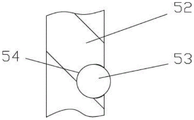
所述推拉机构50包括前后设置的两个侧支撑架51,两个侧支撑架51的中部固定有横向侧板52,两个横向侧板52的右侧壁压靠在上壳体11的前后两个侧板的左侧壁,两个横向侧板52的内侧壁上均设有多个导向球体53,两个侧支撑架51的顶面固定有上推动架60。The push-pull mechanism 50 includes two side support frames 51 arranged at the front and rear. The middle of the two side support frames 51 is fixed with a lateral side plate 52 , and the right side walls of the two lateral side plates 52 are pressed against the front and rear of the upper casing 11 The left side walls of the two side plates and the inner side walls of the two lateral side plates 52 are provided with a plurality of guiding spheres 53 , and the top surfaces of the two side support frames 51 are fixed with an upper push frame 60 .

进一步的说,所述上壳体11的顶板的右侧上成型有右螺接通孔12,进气连接头13通接有右螺接通孔12,上壳体11的顶板的左侧成型有出气螺接通孔14,出气螺接通孔14上通接有排气连接头15,排气连接头15上通接有循环管16,循环管16的上端通接导向壳体17的左侧壁上具有的通孔171,导向壳体17安装在上壳体11的顶板的顶面上,导向壳体17的内腔体与上壳体11的顶板的中部成型有的中心通槽180相通,导向壳体17的顶板的顶面上固定有循环电机18,循环电机18的输出轴伸入导向壳体17中并固定有旋转叶轮181,旋转叶轮181的左侧对着通孔171。Further, a right screw through hole 12 is formed on the right side of the top plate of the upper casing 11 , a right screw through hole 12 is formed in the intake connector 13 , and the left side of the top plate of the upper casing 11 is formed There is an air outlet screw through hole 14, an exhaust connection head 15 is connected to the air outlet screw connection hole 14, a circulation pipe 16 is connected to the exhaust connection head 15, and the upper end of the circulation pipe 16 is connected to the left side of the guide shell 17. There is a through hole 171 on the side wall, the guide casing 17 is installed on the top surface of the top plate of the upper casing 11 , and the inner cavity of the guide casing 17 and the middle of the top plate of the upper casing 11 are formed with a central through groove 180 In the same way, a circulating motor 18 is fixed on the top surface of the top plate of the guide casing 17 .

进一步的说,所述上壳体11的顶板的右部底面固定有下隔板1,下隔板1的侧壁固定在上壳体11的前后两个内侧壁上,下隔板1的底面固定在上壳体11的底板的顶面上,下隔板1上成型有多个通气孔2,右螺接通孔12处于下隔板1的右侧。Further, a lower partition 1 is fixed on the bottom surface of the right part of the top plate of the upper casing 11 , the side walls of the lower partition 1 are fixed on the front and rear inner side walls of the upper casing 11 , and the bottom surface of the lower partition 1 It is fixed on the top surface of the bottom plate of the upper casing 11 , the lower partition plate 1 is formed with a plurality of ventilation holes 2 , and the right screw through hole 12 is located on the right side of the lower partition plate 1 .

进一步的说,所述上壳体11的顶板的中部底面固定有加热连接板3,加热连接板3的底面固定有多个加热棒4。Further, a heating connecting plate 3 is fixed on the bottom surface of the middle part of the top plate of the upper casing 11 , and a plurality of heating rods 4 are fixed on the bottom surface of the heating connecting plate 3 .

进一步的说,所述固定机构43包括两个连接块,两个连接块的顶面具有的柱体固定在升降板42的底面上,连接块的底面固定有两个环形体45,握持部191的顶部横向辊的两端插套在对应的两个环形体45中。Further, the fixing mechanism 43 includes two connecting blocks, the cylinders on the top surfaces of the two connecting blocks are fixed on the bottom surface of the lifting plate 42, the bottom surfaces of the connecting blocks are fixed with two annular bodies 45, Both ends of the top transverse roller of 191 are inserted into the corresponding two annular bodies 45 .

进一步的说,所述两个横向侧板52的内侧壁上均成型有斜向内凹槽54,斜向内凹槽54的内侧壁为弧形壁面,多个导向球体53插套在斜向内凹槽54中,导向球体53的内侧壁紧贴斜向内凹槽54,导向球体53的部分侧壁伸出斜向内凹槽54,斜向内凹槽54的左部低于右部,两个横向侧板52之间的机架10的顶板的顶面固定有斜向导向块55,斜向导向块55的右侧壁紧贴上壳体11的底板的左侧壁,斜向导向块55的左部顶面低于斜向导向块55的右部顶面,斜向导向块55与斜向内凹槽54相配合。Further, the inner side walls of the two lateral side plates 52 are formed with oblique inward grooves 54, the inner side walls of the oblique inward grooves 54 are arc-shaped walls, and a plurality of guiding spheres 53 are inserted and sleeved in the oblique direction. In the inner groove 54, the inner side wall of the guiding sphere 53 is close to the oblique inward groove 54, part of the side wall of the guiding sphere 53 protrudes from the oblique inner groove 54, and the left part of the oblique inner groove 54 is lower than the right part. , an oblique guide block 55 is fixed on the top surface of the top plate of the frame 10 between the two lateral side plates 52 , and the right side wall of the oblique guide block 55 is in close contact with the left side wall of the bottom plate of the upper shell 11 . The left top surface of the guide block 55 is lower than the right top surface of the oblique guide block 55 , and the oblique guide block 55 is matched with the oblique inner groove 54 .

进一步的说,所述升降板42的顶面固定有升降导向杆441,升降导向杆441插套在支撑架40的上横向板上。Further, a lift guide rod 441 is fixed on the top surface of the lift plate 42 , and the lift guide rod 441 is inserted and sleeved on the upper lateral plate of the support frame 40 .

进一步的说,所述门板19的下方具有多个分排气通孔192。Further, the door panel 19 has a plurality of exhaust through holes 192 under the door panel 19 .

进一步的说,所述上推动架60的主顶板61处于两个横向侧板52之间的机架10的顶板的正上方,主顶板61的顶板的左部和右部顶面均固定有竖直连接板62,横向导向螺杆63的两端均通过轴承铰接在两个竖直连接板62上,左部的竖直连接板62的左侧壁上固定有推动电机64,推动电机64的输出轴为花键轴,花键轴插套在横向导向螺杆63的左端具有的花键孔中,移动块65螺接在横向导向螺杆63中,移动块65的底面固定有竖直导向杆66,竖直导向杆66的底端伸出主顶板61的中部具有的横向导向通槽611,竖直导向杆66的底端固定有水平板67,水平板67的顶面固定有升降气缸68,升降气缸68的推杆穿过水平板67的底面并固定有延伸板69,延伸板69的右端固定有推动电磁铁板691,推动电磁铁板691处于水平板67的右方。移动块65的底面固定有自润滑层7,自润滑层7的底面紧贴主顶板61的顶面。Further, the main top plate 61 of the upper push frame 60 is located directly above the top plate of the rack 10 between the two lateral side plates 52, and the left and right top surfaces of the top plate of the main top plate 61 are both fixed with vertical The straight connecting plate 62, both ends of the transverse lead screw 63 are hinged on the two vertical connecting plates 62 through bearings, and a push motor 64 is fixed on the left side wall of the left vertical connecting plate 62, and the output of the push motor 64 is fixed. The shaft is a spline shaft, the spline shaft is inserted into the spline hole at the left end of the transverse lead screw 63, the moving block 65 is screwed into the transverse lead screw 63, and the bottom surface of the moving block 65 is fixed with a vertical guide rod 66, The bottom end of the vertical guide rod 66 protrudes from the lateral guide groove 611 in the middle of the main top plate 61 , the bottom end of the vertical guide rod 66 is fixed with a horizontal plate 67 , and the top surface of the horizontal plate 67 is fixed with a lifting cylinder 68 , The push rod of the air cylinder 68 passes through the bottom surface of the horizontal plate 67 and is fixed with an extension plate 69 . The bottom surface of the moving block 65 is fixed with the self-lubricating layer 7 , and the bottom surface of the self-lubricating layer 7 is in close contact with the top surface of the main top plate 61 .

进一步的说,所述延伸板69的顶面固定有下升降导向杆692,下升降导向杆692插套在水平板67中。Further, a lower lift guide rod 692 is fixed on the top surface of the extension plate 69 , and the lower lift guide rod 692 is inserted into the horizontal plate 67 .

进一步的说,所述加热连接板3包括多个横向板31和多个纵向板32,纵向板32固定在上壳体11的顶板的底面,横向板31固定在所有的纵向向板32的底面,加热棒4固定在纵向板32的底面。Further, the heating connecting plate 3 includes a plurality of transverse plates 31 and a plurality of longitudinal plates 32, the longitudinal plates 32 are fixed on the bottom surface of the top plate of the upper casing 11, and the transverse plates 31 are fixed on the bottom surface of all the longitudinal plates 32 , the heating rod 4 is fixed on the bottom surface of the longitudinal plate 32 .

导向壳体17的底面固定有下安装座179,下安装座179固定在上壳体11的顶板的顶面上,下安装座179的内腔体与导向壳体17的内腔体相通,下安装座179的内腔体与中心通槽180相通。The bottom surface of the guide housing 17 is fixed with a lower mounting seat 179, the lower mounting seat 179 is fixed on the top surface of the top plate of the upper housing 11, and the inner cavity of the lower mounting seat 179 communicates with the inner cavity of the guide housing 17, and the lower mounting seat 179 is connected to the inner cavity of the guide housing 17. The inner cavity of the mounting seat 179 communicates with the central through groove 180 .

所述门板19的右侧的上部设有上挡板9,上挡板9的前侧壁和后侧壁固定在上壳体11的前后两个内侧壁上,并处于出气螺接通孔14的正下方。The upper part of the right side of the door panel 19 is provided with an upper baffle plate 9 , and the front and rear side walls of the upper baffle plate 9 are fixed on the front and rear inner walls of the upper casing 11 , and are located in the air outlet screw through hole 14 . directly below.

本实施例在使用时,将装有待定型的袜子的推车放置在两个横向侧板52之间,通过导向球体53的部分侧壁伸出斜向内凹槽54并靠近待定型的袜子的推车的两个侧板,从而对其实现导向,然后,通过升降气缸68的推杆推动,使得推动电磁铁板691下降并对着推车的左侧板处,然后,通过推动电机64运行,使得横向导向螺杆63转动,使得移动块65向右移动,从而使得推动电磁铁板691向右移动,开启推动电磁铁板691从而吸附在推车的左侧板处将推车向右移动,使得其推入上壳体11中的内部腔体112中,然后,推动电磁铁板691停止运行,通过,推动电机64运行,使得横向导向螺杆63转动,使得移动块65向左移动,移出上壳体11,然后,通过伸缩气缸41的推杆推动,使得门板19下降,使得门板19插套在插槽113和下凹槽114中并覆盖进料口111;When this embodiment is in use, the cart with the socks to be shaped is placed between the two lateral side plates 52, and the inclined inner groove 54 is protruded through part of the side wall of the guide ball 53 and is close to the sock to be shaped. The two side plates of the cart are guided, and then pushed by the push rod of the lifting cylinder 68, so that the push electromagnet plate 691 descends and faces the left side plate of the cart, and then the push motor 64 runs , so that the transverse lead screw 63 rotates, so that the moving block 65 moves to the right, so that the push electromagnet plate 691 moves to the right, and the push electromagnet plate 691 is turned on to be adsorbed on the left side of the cart to move the cart to the right, Make it push into the inner cavity 112 in the upper casing 11, then push the electromagnet plate 691 to stop running, and push the motor 64 to run, so that the transverse lead screw 63 rotates, so that the moving block 65 moves to the left and moves out of the upper The casing 11 is then pushed by the push rod of the telescopic cylinder 41, so that the door panel 19 is lowered, so that the door panel 19 is inserted into the slot 113 and the lower groove 114 and covers the feed port 111;

然后,进气连接头13上通接的蒸汽排气管通入高温蒸汽或热气,对内部腔体112中的袜子进行定型,其中,蒸汽通过下隔板1上的通气孔2进行均布分散进行定型烘干,烘干中,通过循环电机18运行,使得旋转叶轮181旋转,使得对袜子经过烘干后的蒸汽从排气连接头15进入循环管16,然后再进入导向壳体17,再通过中心通槽180再吹到加热棒4上,通过加热棒4的加热,将蒸汽再次升温,再对袜子进行烘干定型,其将蒸汽循环利用,大大提高热量的利用率,加热定型效果好,而当内部腔体112中的气压较高时就会从门板19的下方具有多个分排气通孔192排出,实现减压,其需要的高温蒸汽的输送量可以大大减少,而且将具有余热的蒸汽再次加热,其耗电量也少,加热快速,定型烘干效果好,效率高,热量利用率高,节能环保。Then, high-temperature steam or hot air is passed through the steam exhaust pipe connected to the air inlet connector 13 to shape the socks in the inner cavity 112 , wherein the steam is uniformly distributed and dispersed through the ventilation holes 2 on the lower baffle 1 During drying, the circulating motor 18 is operated to make the rotating impeller 181 rotate, so that the steam after drying the socks enters the circulation pipe 16 from the exhaust connection 15, and then enters the guide shell 17, and then It is blown onto the heating rod 4 through the central through groove 180, and the steam is heated up again by the heating of the heating rod 4, and then the socks are dried and shaped, which recycles the steam, greatly improves the utilization rate of heat, and has a good heating and shaping effect. , and when the air pressure in the inner cavity 112 is high, it will be discharged from the lower part of the door panel 19 with a plurality of exhaust through holes 192 to achieve decompression, and the required amount of high-temperature steam can be greatly reduced. The waste heat steam is reheated, and its power consumption is also small, the heating is fast, the drying effect is good, the efficiency is high, the heat utilization rate is high, and it is energy-saving and environmentally friendly.

完成定型后,通过伸缩气缸41的推杆提升,使得门板19上升,然后,通过推动电机64运行,使得推动电磁铁板691伸入上壳体11中,并开启推动电磁铁板691,从而将推车吸附,然后,通过推动电机64运行。使得推动电磁铁板691向左移动,从而将推车拉出,其自动化程度高,效果好。After completing the setting, the push rod of the telescopic cylinder 41 is lifted to make the door panel 19 rise. Then, the pusher electromagnet plate 691 is extended into the upper casing 11 by the pusher motor 64 to run, and the pusher electromagnet plate 691 is opened, so as to push the electromagnet plate 691 The cart picks up and then runs by pushing the motor 64 . The push electromagnet plate 691 is moved to the left to pull out the cart, which has a high degree of automation and a good effect.

同时,本实施例中,其上壳体11的顶板上还安装有温度传感器、压力传感器等,可以对上壳体11内部的温度和压力实现监控,温度传感器、压力传感器、加热棒4、推动电磁铁板691、推动电机64和循环电机18均通过连接线与控制主机实现电连接,通过控制主机进行控制,而伸缩气缸41和升降气缸68的均通过连接气管与控制阀相连通,控制阀通过连接气管与气泵相连通,气泵、控制阀均与控制主机电连接;At the same time, in this embodiment, a temperature sensor, a pressure sensor, etc. are also installed on the top plate of the upper casing 11, which can monitor the temperature and pressure inside the upper casing 11. The temperature sensor, pressure sensor, heating rod 4, push The electromagnet plate 691, the push motor 64 and the circulation motor 18 are all electrically connected to the control host through connecting wires, and are controlled by the control host, while the telescopic cylinder 41 and the lift cylinder 68 are connected to the control valve through the connecting air pipe, and the control valve The air pump is connected to the air pump by connecting the air pipe, and the air pump and the control valve are all electrically connected with the control host;

推动电磁铁板691、控制主机、温度传感器、压力传感器、加热棒4、气泵、控制阀、推动电机64和循环电机18均为常用公知设备,不再详述,控制主机、气泵、控制阀、温度传感器、压力传感器在附图中也未显示。The push electromagnet plate 691, the control host, the temperature sensor, the pressure sensor, the heating rod 4, the air pump, the control valve, the push motor 64 and the circulation motor 18 are all commonly used and well-known equipment, and will not be described in detail. The control host, the air pump, the control valve, The temperature sensor and pressure sensor are also not shown in the drawings.

最后,以上实施方式仅用于说明本发明,而并非对本发明的限制,有关技术领域的普通技术人员,在不脱离本发明的精神和范围的情况下,还可以做出各种变化和变型,因此所有等同的技术方案也属于本发明的范畴,本发明的专利保护范围应由权利要求限定。Finally, the above embodiments are only used to illustrate the present invention, but not to limit the present invention. Those of ordinary skill in the relevant technical field can also make various changes and modifications without departing from the spirit and scope of the present invention. Therefore, all equivalent technical solutions also belong to the scope of the present invention, and the patent protection scope of the present invention should be defined by the claims.

Claims (10)

1. The utility model provides a full-automatic socks forming machine, includes frame (10), its characterized in that: an upper shell (11) and a support frame (40) are fixed on the top surface of the right side of the top plate of the rack (10), and a push-pull mechanism (50) is arranged on the top surface of the left side of the top plate of the rack (10);
the left side part of the upper shell (11) is provided with a feed inlet (111), and the feed inlet (111) is communicated with an inner cavity (112) of the upper shell (11);
a slot (113) is formed in the left side of the top plate of the upper shell (11), the slot (113) is vertically aligned with a lower groove (114) formed in the top surface of the left part of the bottom plate of the upper shell (11), and the door plate (19) is inserted in the slot (113) and the lower groove (114) and covers the feed port (111);
an upper transverse plate of the support frame (40) is positioned right above the upper shell (11), a telescopic cylinder (41) is fixed on the top surface of the left side of the upper transverse plate of the support frame (40), a push rod of the telescopic cylinder (41) penetrates through the upper transverse plate of the support frame (40) and is fixed with a lifting plate (42), a fixing mechanism (43) is fixed on the bottom surface of the lifting plate (42), the front part and the rear part of the top surface of the door plate (19) are both fixed with a holding part (191), and the upper part of the holding part (191) is fixed on the fixing mechanism (43);
push-and-pull institution (50) are fixed with horizontal curb plate (52) including two side support frame (51) that set up around including, the middle part of two side support frame (51), and the right side wall of two horizontal curb plate (52) is pressed against the left side wall of two front and back curb plates of last casing (11), all is equipped with a plurality of guide ball bodies (53) on the inside wall of two horizontal curb plate (52), and the top surface of two side support frame (51) is fixed with and pushes up frame (60).
2. The full-automatic sock setting machine according to claim 1, wherein: a right screw joint through hole (12) is formed on the right side of a top plate of the upper shell (11), a right screw joint through hole (12) is connected with an air inlet connector (13), an air outlet screw joint through hole (14) is formed on the left side of the top plate of the upper shell (11), an air outlet connector (15) is connected with the air outlet screw joint through hole (14), a circulating pipe (16) is connected with the air outlet connector (15), the upper end of the circulating pipe (16) is connected with a through hole (171) formed in the left side wall of the guide shell (17), the guide shell (17) is installed on the top surface of the top plate of the upper shell (11), the inner cavity of the guide shell (17) is communicated with a central through groove (180) formed in the middle of the top plate of the upper shell (11), a circulating motor (18) is fixed on the top surface of the top plate of the guide shell (17), an output shaft of the circulating motor (18) extends into the guide shell (17) and is fixed with a rotary impeller (181), the left side of the rotary impeller (181) faces the through hole (171).
3. The full-automatic sock setting machine according to claim 2, wherein: the right bottom surface of the top plate of the upper shell (11) is fixed with a lower partition plate (1), the side walls of the lower partition plate (1) are fixed on two inner side walls of the front and the back of the upper shell (11), the bottom surface of the lower partition plate (1) is fixed on the top surface of the bottom plate of the upper shell (11), a plurality of vent holes (2) are formed in the lower partition plate (1), and the right screw connection through hole (12) is located on the right side of the lower partition plate (1).
4. The full-automatic sock setting machine according to claim 2, wherein: and a heating connecting plate (3) is fixed on the bottom surface of the middle part of the top plate of the upper shell (11), and a plurality of heating rods (4) are fixed on the bottom surface of the heating connecting plate (3).
5. The full-automatic sock setting machine according to claim 1, wherein: the fixing mechanism (43) comprises two connecting blocks, columns arranged on the top surfaces of the two connecting blocks are fixed on the bottom surface of the lifting plate (42), two annular bodies (45) are fixed on the bottom surface of the connecting blocks, and two ends of the top transverse roller of the holding part (191) are inserted into the two corresponding annular bodies (45).
6. The full-automatic sock setting machine according to claim 1, wherein: all the shaping has slant inner groovy (54) on the inside wall of two horizontal curb plates (52), the inside wall of slant inner groovy (54) is the arc wall, a plurality of direction spheroid (53) plug bushes are in slant inner groovy (54), slant inner groovy (54) are hugged closely to the inside wall of direction spheroid (53), slant inner groovy (54) are stretched out to the partial lateral wall of direction spheroid (53), the left part of slant inner groovy (54) is less than the right part, the top surface of the roof of frame (10) between two horizontal curb plates (52) is fixed with slant guide block (55), the left side wall of the bottom plate of casing (11) is hugged closely to the right side wall of slant guide block (55), the left part top surface of slant guide block (55) is less than the right part top surface of slant guide block (55), slant guide block (55) cooperate with slant inner groovy (54).
7. The full-automatic sock setting machine according to claim 5, wherein: the top surface of the lifting plate (42) is fixed with a lifting guide rod (441), and the lifting guide rod (441) is inserted and sleeved on the upper transverse plate of the support frame (40).
8. The full-automatic sock setting machine according to claim 5, wherein: the lower part of the door panel (19) is provided with a plurality of sub exhaust through holes (192).
9. The full-automatic sock setting machine according to claim 1, wherein: the main top plate (61) of the upper pushing frame (60) is positioned right above the top plate of the rack (10) between the two transverse side plates (52), vertical connecting plates (62) are fixed on the top surfaces of the left part and the right part of the top plate of the main top plate (61), two ends of a transverse guide screw (63) are hinged to the two vertical connecting plates (62) through bearings, a pushing motor (64) is fixed on the left side wall of the vertical connecting plate (62) of the left part, an output shaft of the pushing motor (64) is a spline shaft, the spline shaft is inserted and sleeved in a spline hole formed in the left end of the transverse guide screw (63), a moving block (65) is screwed in the transverse guide screw (63), a vertical guide rod (66) is fixed on the bottom surface of the moving block (65), the bottom end of the vertical guide rod (66) extends out of a transverse guide through groove (611) formed in the middle of the main top plate (61), a horizontal plate (67) is fixed at the bottom end of the vertical guide rod (66), a lifting cylinder (68) is fixed on the top surface of the horizontal plate (67), a push rod of the lifting cylinder (68) penetrates through the bottom surface of the horizontal plate (67) and is fixed with an extension plate (69), a push electromagnet plate (691) is fixed at the right end of the extension plate (69), and the push electromagnet plate (691) is positioned on the right side of the horizontal plate (67).
10. The full-automatic sock setting machine of claim 9, wherein: a lower elevation guide bar (692) is fixed to the top surface of the extension plate (69), and the lower elevation guide bar (692) is inserted into the horizontal plate (67).
CN202010415844.8A 2020-05-16 2020-05-16 Full-automatic sock setting machine Active CN111411470B (en)

Priority Applications (1)

Application Number Priority Date Filing Date Title
CN202010415844.8A CN111411470B (en) 2020-05-16 2020-05-16 Full-automatic sock setting machine

Applications Claiming Priority (1)

Application Number Priority Date Filing Date Title
CN202010415844.8A CN111411470B (en) 2020-05-16 2020-05-16 Full-automatic sock setting machine

Publications (2)

Publication Number Publication Date
CN111411470A CN111411470A (en) 2020-07-14
CN111411470B true CN111411470B (en) 2022-09-02

Family

ID=71492367

Family Applications (1)

Application Number Title Priority Date Filing Date
CN202010415844.8A Active CN111411470B (en) 2020-05-16 2020-05-16 Full-automatic sock setting machine

Country Status (1)

Country Link
CN (1) CN111411470B (en)

Citations (4)

* Cited by examiner, † Cited by third party
Publication number Priority date Publication date Assignee Title
GB732993A (en) * 1951-10-22 1955-07-06 Kurt Frowein A method of dyeing and setting ladies' stockings
KR200428793Y1 (en) * 2006-07-21 2006-10-16 김창훈 Socks Steam Setter
CN207958755U (en) * 2018-03-09 2018-10-12 诸暨市美锦针织有限公司 A kind of socks processing sock molding equipment being heated evenly
CN110438708A (en) * 2019-09-10 2019-11-12 嘉兴亿豪新材料股份有限公司 A kind of efficient sock molding device

Patent Citations (4)

* Cited by examiner, † Cited by third party
Publication number Priority date Publication date Assignee Title
GB732993A (en) * 1951-10-22 1955-07-06 Kurt Frowein A method of dyeing and setting ladies' stockings
KR200428793Y1 (en) * 2006-07-21 2006-10-16 김창훈 Socks Steam Setter
CN207958755U (en) * 2018-03-09 2018-10-12 诸暨市美锦针织有限公司 A kind of socks processing sock molding equipment being heated evenly
CN110438708A (en) * 2019-09-10 2019-11-12 嘉兴亿豪新材料股份有限公司 A kind of efficient sock molding device

Also Published As

Publication number Publication date
CN111411470A (en) 2020-07-14

Similar Documents

Publication Publication Date Title
CN104195781B (en) Integrated device for shaping and demoulding socks
CN202965033U (en) Heating system applied to vacuum vulcanizing machine
CN202830573U (en) Energy-saving type industrial dryer
CN111411470B (en) Full-automatic sock setting machine
CN201942895U (en) Steam setting machine
CN102342578A (en) Efficient air source low-carbon tobacco drying equipment
CN206826147U (en) A kind of intaglio press drying box
CN205762623U (en) A kind of rinsing machine for shoemaking
CN216481922U (en) Automatic drying equipment of natural crab shell
CN208068798U (en) A kind of water type die heater with cooling device
CN204373337U (en) A kind of cylinder feed drying equipment
CN104957788B (en) Circulation oil bath type cup thermo-pressing moulder
CN204039736U (en) A kind of sock molding takes off socks integrated device
CN210688980U (en) Energy-saving laundry piece drying device
CN221479770U (en) Quick desiccator of mud
CN208815352U (en) Vapor recycles and improves the device of drying efficiency in paper pulp moulding drying system
CN222560561U (en) A spiral air drying device for materials
CN220562127U (en) Heat conduction liquid circulating device of mold temperature machine
CN223143814U (en) Vinegar rhizoma corydalis steaming equipment
CN219141413U (en) Glazed tile drying rack
CN218764306U (en) Paper products rack convenient to it is dry
CN219415496U (en) Double-circulation mode drying box
CN213778466U (en) Quick drying device is used in animal remedy pellet production
CN205825625U (en) A kind of for fish silk making rapid drying device
CN113418356B (en) Energy-saving and carbon-reducing technology and device for building material enterprise

Legal Events

Date Code Title Description
PB01 Publication
PB01 Publication
SE01 Entry into force of request for substantive examination
TA01 Transfer of patent application right

Effective date of registration: 20220817

Address after: 317500 No. 97, Muyu Youth Road, Zeguo Town, Wenling City, Taizhou City, Zhejiang Province

Applicant after: Song Weijie

Address before: 318000 No. 169, Huajing village, Jiajia street, Jiaojiang District, Taizhou City, Zhejiang Province

Applicant before: Taizhou Jiaojiang Zhiya Clothing Co.,Ltd.

TA01 Transfer of patent application right
GR01 Patent grant
GR01 Patent grant
TR01 Transfer of patent right

Effective date of registration: 20230509

Address after: 247299 No. 118, Meicheng Road, Yaodu Town, Dongzhi County, Chizhou City, Anhui Province

Patentee after: ANHUI YAOYU INTELLIGENT SOCK INDUSTRY Co.,Ltd.

Address before: 317500 No. 97, Muyu Youth Road, Zeguo Town, Wenling City, Taizhou City, Zhejiang Province

Patentee before: Song Weijie

CP03 Change of name, title or address

Address after: No. 118, Meicheng Road, Yaodu Town, Dongzhi County, Chizhou, Anhui Province 247100

Patentee after: Anhui Yaoshun Intelligent Technology Group Co.,Ltd.

Country or region after: China

Address before: 247299 No. 118, Meicheng Road, Yaodu Town, Dongzhi County, Chizhou City, Anhui Province

Patentee before: ANHUI YAOYU INTELLIGENT SOCK INDUSTRY Co.,Ltd.

Country or region before: China

CP03 Change of name, title or address
PE01 Entry into force of the registration of the contract for pledge of patent right

Denomination of invention: A fully automatic sock shaping machine

Granted publication date: 20220902

Pledgee: Anhui Dongzhi Rural Commercial Bank Co.,Ltd.

Pledgor: Anhui Yaoshun Intelligent Technology Group Co.,Ltd.

Registration number: Y2024980038757

PE01 Entry into force of the registration of the contract for pledge of patent right
PC01 Cancellation of the registration of the contract for pledge of patent right

Granted publication date: 20220902

Pledgee: Anhui Dongzhi Rural Commercial Bank Co.,Ltd.

Pledgor: Anhui Yaoshun Intelligent Technology Group Co.,Ltd.

Registration number: Y2024980038757

PC01 Cancellation of the registration of the contract for pledge of patent right
PE01 Entry into force of the registration of the contract for pledge of patent right

Denomination of invention: A fully automatic sock shaping machine

Granted publication date: 20220902

Pledgee: Agricultural Bank of China Limited Dongzhi County Branch

Pledgor: Anhui Yaoshun Intelligent Technology Group Co.,Ltd.

Registration number: Y2024980058379

PE01 Entry into force of the registration of the contract for pledge of patent right