Disclosure of Invention
The present invention aims to solve at least one of the above technical problems to a certain extent. Therefore, the invention aims to provide the glass pendulum material UV machine which is labor-saving and capable of improving the production efficiency of products.
A glass pendulum material point UV machine that glues, including the tool used for conveying the tool plate conveys the assembly, fix to the some glue assembly above the tool conveying assembly, and main stander fixed with one end of the tool conveying assembly; a first sliding table and a second sliding table are fixedly arranged on the main frame, a double-station material taking assembly is movably arranged on the first sliding table, a material pushing manipulator is movably arranged on the second sliding table, and a glass breaking mechanism is also fixed on the main frame;
in one embodiment, the glass breaking mechanism comprises two groups of supporting plates fixed on the main frame, a cylinder mounting plate fixed between the two groups of supporting plates, a first cylinder vertically fixed on the cylinder mounting plate, and a pressing guide rail mounting plate fixed with a floating joint of the first cylinder; wherein one side of backup pad still is fixed with first guide rail mounting panel, installs first guide rail on the first guide rail mounting panel, presses the both ends movable mounting of material guide rail mounting panel on first guide rail, presses the bottom of material guide rail mounting panel still to be fixed with the rupture connecting plate, and fixes through first guide post press the fixed rupture clamp plate of material guide rail mounting panel below, through the outside cover of second guide post establish the pressure spring after movable mounting press the movable rupture clamp plate of material guide rail mounting panel below, there is the difference in height between the minimum of the mounted position of movable rupture clamp plate and fixed rupture clamp plate, the movable rupture clamp plate with fixed rupture clamp plate is equipped with the square arch of quantity such as.
In one embodiment, the glass breaking mechanism further comprises a second guide rail mounting plate fixed on the main frame, two groups of second guide rails and second air cylinders are fixedly mounted on the second guide rail mounting plate, and a sliding connecting block, a support plate fixed on the sliding connecting block and a glass jig are movably mounted on the second guide rails; the glass jig is used for bearing the weight of glass board and the upper end is equipped with a plurality of square grooves that correspond with square protruding width and quantity, drives activity rupture clamp plate downstream through first cylinder, and square protruding alignment square groove is pressed and is rolled over, utilizes the resilience force of pressure spring to break the glass board in the activity rupture clamp plate.
In one embodiment, the jig conveying assembly comprises a support frame, a conveyor belt arranged on the support frame, and a positioning jig fixed on the conveyor belt, wherein the positioning jig is positioned right below the dispensing assembly and used for fixing and clamping the jig plate.
In one embodiment, the dispensing assembly comprises a dispensing support frame fixed on the ground, a three-axis moving assembly mounted on the dispensing support frame, and a dispensing robot fixed on the three-axis moving assembly.
In one embodiment, the double-station material taking assembly comprises a material taking mounting plate fixed on the first sliding table, and a jig plate manipulator and a glass placing manipulator which are fixed on the material taking mounting plate.
In one embodiment, the glass storage bin lifting mechanism is fixed on the main frame and comprises a storage bin which is formed by longitudinally partitioning a plurality of groups of baffles, a supporting plate is arranged at the bottom of the storage bin, a top column is movably mounted at the bottom of the supporting plate, a top plate is fixed at the bottom of the top column, a screw-nut mechanism is fixed at the lower end of the top plate, and a servo motor drives the screw-nut mechanism to drive the top column to upwards push and extend, so that a glass plate in the storage bin is ejected.
In one embodiment, the lower end of the glass material placing manipulator is provided with a plurality of groups of vacuum suction nozzles for adsorbing glass plates side by side, the lower end of the jig plate manipulator is provided with a clamping jaw driven by a clamping cylinder, and the jig plate is taken and placed by the clamping jaw.
In one embodiment, a jig positioning station is further arranged on one side of the glass breaking mechanism, a UV conveyor belt is arranged on the jig positioning station, and a UV local furnace for UV curing of glass cement is further arranged above the UV conveyor belt.
In one embodiment, the lower end of the pushing manipulator is provided with a pressing plate, the lower end of the pressing plate is provided with a plurality of groups of pushing plates in parallel, and the pushing plates are used for pushing the glass plates on the storage bin to the glass breaking mechanism.
The invention has the beneficial effects that:
the jig plate glue dispensing, glass plate breaking, feeding and UV curing are all completed by a manipulator, wherein a breaking mechanism is provided with two groups of breaking plates, one group of breaking plates is used for fixing and limiting the glass plate, and the other group of breaking plates vertically break the glass plate, so that the broken glass plate has smooth edge and low edge breakage rate; the storage bin is designed in a multi-group side-by-side mode, glass is manually loaded into the storage bin and positioned, the motor drives the screw rod nut mechanism to upwards push and extend according to the thickness of the glass, and then a push plate of the material pushing manipulator pushes the glass plate to the glass breaking mechanism to be broken; above-mentioned operation except feed bin supply glass board and get the finished product that the processing is good, other operations are accomplished by automation equipment, and the mechanism of this scheme compares that traditional semi-automatic point is glued and is swung piece rupture technological efficiency is higher, saves the cost of labor.
Detailed Description
The technical solutions in the embodiments of the present invention will be clearly and completely described below with reference to the drawings in the embodiments of the present invention, and it is obvious that the described embodiments are only a part of the embodiments of the present invention, and not all of the embodiments.
All other embodiments, which can be derived by a person skilled in the art from the embodiments given herein without making any creative effort, shall fall within the protection scope of the present invention.
It should be noted that all the directional indications (such as up, down, left, right, front, back, inner and outer, center … …) in the embodiment of the present invention are only used to explain the relative position relationship between the components, the motion situation, etc. in a specific posture (as shown in the drawing), and if the specific posture is changed, the directional indication is changed accordingly.
In the present invention, unless otherwise expressly stated or limited, the terms "connected," "secured," and the like are to be construed broadly, and for example, "secured" may be a fixed connection, a removable connection, or an integral part; can be mechanically or electrically connected; they may be directly connected or indirectly connected through intervening media, or they may be connected internally or in any other suitable relationship, unless expressly stated otherwise. The specific meanings of the above terms in the present invention can be understood by those skilled in the art according to specific situations.
In addition, the technical solutions in the embodiments of the present invention may be combined with each other, but it must be based on the realization of those skilled in the art, and when the technical solutions are contradictory or cannot be realized, such a combination of technical solutions should not be considered to exist, and is not within the protection scope of the present invention.
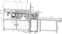
As shown in fig. 1 to 3, a glass pendulum material dispensing UV machine includes a jig conveying assembly 1 for conveying a jig plate, a dispensing assembly 2 disposed above the jig conveying assembly 1, and a main frame 3 fixed to one end of the jig conveying assembly 1; a first sliding table 4 and a second sliding table 5 are fixedly arranged on the main frame 3, a double-station material taking assembly 41 is movably arranged on the first sliding table 4, a material pushing manipulator 51 is movably arranged on the second sliding table 5, and a glass breaking mechanism 6 is also fixed on the main frame 3;
in a preferred embodiment, the glass breaking mechanism 6 includes two sets of support plates 61 fixed on the main frame 3, a cylinder mounting plate 62 fixed between the two sets of support plates 61, a first cylinder 63 vertically fixed on the cylinder mounting plate 62, a pressing guide mounting plate 64 fixed with a floating joint 631 of the first cylinder 63; wherein, one side of the supporting plate 61 is also fixed with a first guide rail mounting plate 65, a first guide rail 651 is arranged on the first guide rail mounting plate 65, two ends of the material pressing guide rail mounting plate 64 are movably arranged on the first guide rail 651, the bottom end of the material pressing guide rail mounting plate 64 is also fixed with a breaking connecting plate 66, and a fixed break-off pressing plate 642 fixed below the swaging guide rail mounting plate 64 by a first guide post 671, the movable break-off pressing plate 641 is movably arranged below the material pressing guide rail mounting plate 64 after a pressure spring 673 is sleeved outside the second guide column 672, the height difference exists between the lowest points of the mounting positions of the movable break-off pressing plate 641 and the fixed break-off pressing plate 642, square bulges 6411 with equal quantity are arranged on the movable break-off pressing plate 641 and the fixed break-off pressing plate 642, a silica gel pad 6412 is further disposed at the bottom end of the square protrusion 6411, and a pressure spring 673 is specifically disposed between the movable fracture pressing plate 641 and the fracture connecting plate 642.
In one embodiment, the glass breaking mechanism 6 further includes a second guide rail mounting plate 68 fixed on the main frame 3, two sets of second guide rails 681 and one set of second cylinders 682 are fixedly mounted on the second guide rail mounting plate 68, and a sliding connection block 683, and a carrier plate 684 and a glass jig 685 fixed on the sliding connection block 683 are movably mounted on the second guide rails 681;
in one preferred embodiment, the glass jig 685 is used for carrying glass plates and has square grooves 6851 at the upper end corresponding to the width and number of the square protrusions 6411; more specifically, the glass plate adopted in this embodiment is in a long strip shape, the width of the glass plate corresponds to the width of the square groove 6851, the glass plate is placed on the square groove 6851 before being broken, wherein the front end of the glass plate extends towards the direction in which the square groove 6851 is far away from the storage bin 72, the portion of the glass plate extending outwards is the broken portion, when the first cylinder 63 drives the pressing rail mounting plate 642 to drive the movable breaking pressing plate 641 to press downwards, because the movable breaking pressing plate 641 and the fixed breaking pressing plate 642 have a height difference during installation, and the installation position of the movable breaking pressing plate 641 is lower than that of the fixed breaking pressing plate 642, when the movable breaking pressing plate 641 is pressed downwards, the first square protrusion 6411a of the movable breaking pressing plate 641 first contacts the glass plate located in the square groove 6851, and the glass plate in the square groove 6851 is gradually pressed by the resilience force generated by the pressing spring 673, until the lowest point of the fixed breaking pressing plate 642 and the lowest point of the movable breaking pressing plate 641 are in the same horizontal plane, the fixed breaking pressing plate 642 breaks the outward extending part of the glass plate through the second square protrusion 6411 b; the glass breaking mechanism adopted in the embodiment has the advantages that the glass plate is limited left and right through the direction groove 6851, the glass plate is limited front and back and up and down through the elasticity of the pressure spring 673 of the movable breaking pressure plate 641, and the breaking precision is not high due to the shaking of the glass plate during the pressing and breaking process, in the preferred scheme of the embodiment, the width of the square protrusion 6411 corresponds to the width of the square groove 6851, so that the fixed breaking pressure plate 642 ensures the maximum contact surface with the glass plate during the pressing and breaking process, the shaking of the glass plate is reduced to the maximum extent during the breaking process through the glass breaking mechanism in the embodiment, and the purpose of arranging the silica gel pad 6412 is also to increase the static friction generated when the movable breaking pressure plate 641 is contacted with the glass plate.
In one embodiment, the jig conveying assembly 1 includes a support frame 11, a conveyor belt 12 disposed on the support frame 11, and a positioning jig 13 fixed on the conveyor belt 12, wherein an optical fiber sensor 14 is further disposed at one end of the positioning jig 13, and the positioning jig 13 is located directly below the dispensing assembly 2 and used for fixing and positioning a jig plate.
In one embodiment, the dispensing assembly 2 includes a dispensing support frame 21 fixed on the floor, a three-axis motion assembly 22 mounted on the dispensing support frame 21, and a dispensing robot 23 fixed on the three-axis motion assembly 22.
In one embodiment, the double-station material taking assembly 41 comprises a material taking mounting plate 411 fixed on the first sliding table 4, and a jig plate manipulator 412 and a glass placing manipulator 413 fixed on the material taking mounting plate 411; the lower end of the glass material placing manipulator 413 is provided with a plurality of groups of vacuum suction nozzles 4131 used for adsorbing glass plates side by side, the lower end of the jig plate manipulator 412 is provided with a clamping jaw 4121 driven by a clamping cylinder, and the taking and placing of the jig plate are realized through the clamping jaw 4121.
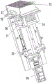
In one embodiment, the glass material placing and dispensing UV machine further comprises a glass bin lifting mechanism 7 fixed on the main frame 3, the glass bin lifting mechanism 7 comprises a bin 72 longitudinally partitioned by a plurality of groups of baffles 71, a supporting plate 73 is arranged at the bottom of the bin 72, a top column 74 is movably installed at the bottom of the supporting plate 73, a top plate 77 is fixed at the bottom of the top column 74, a screw-nut mechanism 75 is fixed at the lower end of the top plate 77, and the top column 74 is driven to extend upwards and upwards through a servo motor 76 located at the bottom end of the screw-nut mechanism 75, so that a glass plate in the bin 72 is ejected; specifically, the glass plate is manually placed in the storage bin 72, the servo motor 76 drives the screw rod and nut mechanism 75 to drive the ejection column to eject upwards, and the ejection height is set according to the thickness of the glass plate.
In one embodiment, a jig positioning station 10 is further arranged on one side of the glass breaking mechanism 7, a UV conveyor belt 8 is arranged on the jig positioning station 10, and a UV local furnace 9 for UV curing of glass cement is further arranged above the UV conveyor belt 8.
In one embodiment, a pressing plate 511 is arranged at the lower end of the pushing manipulator 51, a plurality of groups of pushing plates 512 are arranged at the lower end of the pressing plate 511 in parallel, and the pushing plates 512 are used for pushing the glass plates on the storage bin to the glass breaking mechanism; specifically, the number and the width of the push plates 512 correspond to the number and the width of the gaps between the baffle plates 71, so that when the glass plate on the storage bin 72 is ejected, the push plates 512 can push the glass plate onto the positioning jig 13;
it needs to be further explained that the working principle of the invention is as follows:
1. the glass jig plate is manually placed on the conveyor belt 12, the glass jig plate is conveyed to the dispensing station through the conveyor belt 12, and after the optical fiber sensor 14 detects a material signal, the cylinder of the positioning jig 13 is ejected out to position the glass jig plate.
2. The triaxial moving assembly drives the dispensing mechanical arm to automatically dispense the glass jig plate according to the set parameters, after dispensing is completed, the cylinder of the positioning jig 13 returns, the glass jig plate is conveyed to the tail end of the conveying belt 12, the clamping jaw 4121 of the jig plate mechanical arm 412 clamps the glass jig plate, the glass jig plate is placed on the jig positioning station 10 through the first sliding table 4, and positioning is performed through the positioning cylinder behind the jig positioning station 10.
3. The servo motor 76 drives the screw and nut mechanism 75 to drive the ejection column to eject upwards, and after the glass plate is ejected out of the storage bin, the push plate 512 at the lower end of the material-ejecting manipulator 51 pushes the glass plate to the square groove 6851, wherein the distance of each pushing is determined according to the length of an actually processed product, wherein the longer the length of the glass plate extending to the outer side of the square groove 6851 is, the longer the length of the finally broken glass product is.
4. The second cylinder 682 pushes the carrier plate 684 and the glass fixture 685 located on the carrier plate 684 to slide on the second guide rail 681 until the movable break-off press plate 641 is located directly above the square groove 6851.
5. After the material pushing manipulator pushes the product in place, the glass breaking mechanism 6 drives the material pressing guide rail mounting plate 642 by the first cylinder 63 to drive the movable breaking pressing plate 641 to press downwards, the fixed breaking pressing plate 642 breaks the part of the glass plate extending outwards through the second square protrusion 6411b, the broken glass slides on the carrier plate 684, the glass placing manipulator 413 moves right above the carrier plate through the first sliding table 41, the glass placing manipulator 413 is driven by the Z-axis motor to move downwards and then the vacuum suction nozzle 4131 is opened, the broken glass is sucked up and placed on the glass jig plate located on the jig positioning station 10 in sequence.
6. And (4) repeating the operation of the step (4), after the glass jig plate is full of glass, retracting the air cylinder of the jig positioning station 10, enabling the glass jig plate to fall on the UV conveyor belt, and enabling the UV conveyor belt 8 to drive the glass jig plate filled with glass to pass through the UV local furnace to solidify the UV glue, so that all the operations are completed.
The above is only a preferred embodiment of the present invention, and is not intended to limit the present invention, and various modifications and changes will occur to those skilled in the art. Any modification, equivalent replacement, or improvement made within the spirit and principle of the present invention should be included in the protection scope of the present invention.