CN111336431A - High-efficient radiating waterproof computer lamp holder of shaking head - Google Patents
High-efficient radiating waterproof computer lamp holder of shaking head Download PDFInfo
- Publication number
- CN111336431A CN111336431A CN202010187680.8A CN202010187680A CN111336431A CN 111336431 A CN111336431 A CN 111336431A CN 202010187680 A CN202010187680 A CN 202010187680A CN 111336431 A CN111336431 A CN 111336431A
- Authority
- CN
- China
- Prior art keywords
- lamp body
- lamp
- shell
- main body
- air
- Prior art date
- Legal status (The legal status is an assumption and is not a legal conclusion. Google has not performed a legal analysis and makes no representation as to the accuracy of the status listed.)
- Pending
Links
Images


Classifications
-
- F—MECHANICAL ENGINEERING; LIGHTING; HEATING; WEAPONS; BLASTING
- F21—LIGHTING
- F21S—NON-PORTABLE LIGHTING DEVICES; SYSTEMS THEREOF; VEHICLE LIGHTING DEVICES SPECIALLY ADAPTED FOR VEHICLE EXTERIORS
- F21S8/00—Lighting devices intended for fixed installation
-
- F—MECHANICAL ENGINEERING; LIGHTING; HEATING; WEAPONS; BLASTING
- F21—LIGHTING
- F21V—FUNCTIONAL FEATURES OR DETAILS OF LIGHTING DEVICES OR SYSTEMS THEREOF; STRUCTURAL COMBINATIONS OF LIGHTING DEVICES WITH OTHER ARTICLES, NOT OTHERWISE PROVIDED FOR
- F21V17/00—Fastening of component parts of lighting devices, e.g. shades, globes, refractors, reflectors, filters, screens, grids or protective cages
- F21V17/10—Fastening of component parts of lighting devices, e.g. shades, globes, refractors, reflectors, filters, screens, grids or protective cages characterised by specific fastening means or way of fastening
- F21V17/12—Fastening of component parts of lighting devices, e.g. shades, globes, refractors, reflectors, filters, screens, grids or protective cages characterised by specific fastening means or way of fastening by screwing
-
- F—MECHANICAL ENGINEERING; LIGHTING; HEATING; WEAPONS; BLASTING
- F21—LIGHTING
- F21V—FUNCTIONAL FEATURES OR DETAILS OF LIGHTING DEVICES OR SYSTEMS THEREOF; STRUCTURAL COMBINATIONS OF LIGHTING DEVICES WITH OTHER ARTICLES, NOT OTHERWISE PROVIDED FOR
- F21V29/00—Protecting lighting devices from thermal damage; Cooling or heating arrangements specially adapted for lighting devices or systems
- F21V29/50—Cooling arrangements
- F21V29/60—Cooling arrangements characterised by the use of a forced flow of gas, e.g. air
- F21V29/67—Cooling arrangements characterised by the use of a forced flow of gas, e.g. air characterised by the arrangement of fans
-
- F—MECHANICAL ENGINEERING; LIGHTING; HEATING; WEAPONS; BLASTING
- F21—LIGHTING
- F21V—FUNCTIONAL FEATURES OR DETAILS OF LIGHTING DEVICES OR SYSTEMS THEREOF; STRUCTURAL COMBINATIONS OF LIGHTING DEVICES WITH OTHER ARTICLES, NOT OTHERWISE PROVIDED FOR
- F21V29/00—Protecting lighting devices from thermal damage; Cooling or heating arrangements specially adapted for lighting devices or systems
- F21V29/50—Cooling arrangements
- F21V29/70—Cooling arrangements characterised by passive heat-dissipating elements, e.g. heat-sinks
- F21V29/83—Cooling arrangements characterised by passive heat-dissipating elements, e.g. heat-sinks the elements having apertures, ducts or channels, e.g. heat radiation holes
-
- F—MECHANICAL ENGINEERING; LIGHTING; HEATING; WEAPONS; BLASTING
- F21—LIGHTING
- F21V—FUNCTIONAL FEATURES OR DETAILS OF LIGHTING DEVICES OR SYSTEMS THEREOF; STRUCTURAL COMBINATIONS OF LIGHTING DEVICES WITH OTHER ARTICLES, NOT OTHERWISE PROVIDED FOR
- F21V31/00—Gas-tight or water-tight arrangements
- F21V31/005—Sealing arrangements therefor
-
- F—MECHANICAL ENGINEERING; LIGHTING; HEATING; WEAPONS; BLASTING
- F21—LIGHTING
- F21W—INDEXING SCHEME ASSOCIATED WITH SUBCLASSES F21K, F21L, F21S and F21V, RELATING TO USES OR APPLICATIONS OF LIGHTING DEVICES OR SYSTEMS
- F21W2131/00—Use or application of lighting devices or systems not provided for in codes F21W2102/00-F21W2121/00
- F21W2131/40—Lighting for industrial, commercial, recreational or military use
- F21W2131/406—Lighting for industrial, commercial, recreational or military use for theatres, stages or film studios
Abstract
The invention relates to the technical field of stage lamps, in particular to a waterproof computer shaking head lamp holder capable of efficiently dissipating heat. The utility model provides a high-efficient radiating waterproof computer lamp holder of shaking head, includes the lamp body of the metal construction that is equipped with the cavity and locates shell on the lamp body is global, the shell with form an air runner between the lamp body and be located in the air runner the afterbody of lamp body is provided with the fan, correspond on the shell the position of fan is provided with the air intake, still be provided with the air outlet on the shell. In the invention, the cavity is used for installing the light source component, and the lamp body is taken as a whole, so that the waterproof treatment is convenient; on heat conduction that the light source subassembly produced the lamp body of metal construction, the rethread setting directly dispels the heat for the lamp body at the fan of lamp body afterbody, need not install special radiator again and dispel the heat for this device structure is simpler, has reduced manufacturing cost.
Description
Technical Field
The invention relates to the technical field of stage lamps, in particular to a waterproof computer shaking head lamp holder capable of efficiently dissipating heat.
Background
Waterproof computer lamp of shaking head more than original bubble light source IP65 is in the use, and built-in light source subassembly can produce a large amount of heats, and the heat of production if can not in time handle, will influence the life-span of light source subassembly. For carrying out the heat dissipation processing to light source module, current waterproof computer is shaken the head and is generally carried out the heat dissipation processing through installing the radiator additional, utilizes the radiator to derive the heat and dispel the heat to the radiator through the fan to reduce the inside temperature of lamp body. Because the lamp body shell can only naturally dissipate heat through contact with air, the heat dissipation efficiency is low. In addition, because the radiator needs to be sealed with the inside of the lamp body, the adoption of the radiating structure can cause the manufacturing process of the computer moving head lamp to be complex, the waterproof structure to be complex, the cost to be high and the weight to be heavy.
Disclosure of Invention
The invention provides the waterproof computer moving head lamp holder with high-efficiency heat dissipation, aiming at overcoming the problems of complex manufacturing process, high cost and complex waterproof structure of the computer moving head lamp in the prior art.
In order to solve the technical problems, the invention adopts the technical scheme that: the utility model provides a high-efficient radiating waterproof computer lamp holder of shaking head, includes the lamp body of the metal construction that is equipped with the cavity and locates shell on the lamp body is global, the shell with form an air runner between the lamp body and be located in the air runner the afterbody of lamp body is provided with the fan, correspond on the shell the position of fan is provided with the air intake, still be provided with the air outlet on the shell.
In the technical scheme, the cavity is used for installing the light source component, and the lamp body is taken as a whole, so that waterproof treatment is facilitated; on heat conduction that the light source subassembly produced the lamp body of metal construction, the rethread setting directly dispels the heat for the lamp body at the fan of lamp body afterbody, need not install special radiator again and dispel the heat for this device structure is simpler, has reduced manufacturing cost.
Preferably, a notch structure for air discharge is provided on an outer edge of the housing on the side adjacent to the housing provided with the air outlet.
Preferably, the lamp body at least comprises a first main body and a second main body which are detachably connected, the fan is fixedly arranged at the tail of the first main body, and the second main body is provided with an opening structure through which light passes.
Preferably, the lamp body further comprises a connecting body for connecting the first main body and the second main body, and a cavity formed by the first main body, the connecting body and the second main body is used for installing a light source assembly.
Preferably, threaded holes are formed in end faces, connected with the first main body and the second main body, of the connecting body, first mounting holes corresponding to the threaded holes are formed in the first main body, and second mounting holes corresponding to the threaded holes are formed in the second main body.
Preferably, the connecting body is symmetrically provided with shaft holes for connecting the lamp body and the rotating shaft.
Preferably, the shell comprises two groups of symmetrically arranged shells, and the two groups of shells are respectively in threaded connection with the lamp body.
Preferably, through hole structures matched with the shaft holes are arranged at the connecting parts of the two groups of shell side parts, and the air inlets are formed at the connecting parts of the two groups of shell bottoms; the air outlets are arranged in two groups, and the two groups of air outlets are symmetrically arranged on the shell.
Preferably, a groove structure is arranged on the lamp body along the circumferential surface, and the outer edge of the shell provided with the air outlet is connected with the groove structure in a sealing manner.
Preferably, the lamp body is provided with a plurality of rib structures for heat dissipation; the lamp body is of an aluminum alloy structure, and the shell is of a plastic structure.
Compared with the prior art, the beneficial effects are:
in the invention, the cavity is used for installing the light source component, and the lamp body is taken as a whole, so that the waterproof treatment is convenient; the heat generated by the light source component is conducted to the lamp body with the metal structure, an air flow channel is formed between the shell and the lamp body with the metal structure, and then the heat of the lamp body is directly dissipated through the fan arranged at the tail of the lamp body, so that the air flow near the outer side of the lamp body with the metal structure is accelerated, and the heat dissipation efficiency is improved; the air flow channel effectively increases the area for forced convection heat dissipation of the lamp body, so that most area of the lamp body is in the forced convection, and the weight of the lamp body can be remarkably reduced under the condition of multiple smaller lamp body volume by only effectively controlling the strength of the forced convection in the heat dissipation principle, and the same heat dissipation effect can be achieved; the invention does not need to install a special radiator for heat dissipation, so that the device has simpler structure, light weight and small volume and reduces the production cost.
Drawings
FIG. 1 is an exploded view of the waterproof computer moving head light of the present invention;
FIG. 2 is a perspective view of the waterproof computer moving head lamp of the present invention;
FIG. 3 is a perspective view of the housing of the present invention;
fig. 4 is a perspective view of a lamp body in the present invention;
FIG. 5 is a perspective view of a first body of the present invention;
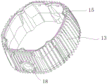
FIG. 6 is a perspective view of a connector of the present invention;
FIG. 7 is a perspective view of a second body in the present invention;
FIG. 8 is a schematic block diagram of the heat dissipation of the present invention I;
FIG. 9 is a schematic diagram of the heat dissipation of the present invention, FIG. II;
FIG. 10 is a schematic block diagram III of the heat dissipation of the present invention;
the lamp comprises a lamp body 1, a cavity 2, a shell 3, a fan 4, an air inlet 5, an air outlet 6, a rotating shaft 7, an air flow channel 8, a notch structure 9, a first main body 11, a second main body 12, a connector 13, an opening structure 14, a threaded hole 15, a first mounting hole 16, a second mounting hole 17, an axial hole 18, a groove structure 19, a rib structure 20, a shell 31, a through hole 32 and an outer edge 34.
Detailed Description
The drawings are for illustrative purposes only and are not to be construed as limiting the patent; for the purpose of better illustrating the embodiments, certain features of the drawings may be omitted, enlarged or reduced, and do not represent the size of an actual product; it will be understood by those skilled in the art that certain well-known structures in the drawings and descriptions thereof may be omitted. The positional relationships depicted in the drawings are for illustrative purposes only and are not to be construed as limiting the present patent.
The same or similar reference numerals in the drawings of the embodiments of the present invention correspond to the same or similar components; in the description of the present invention, it should be understood that if there are terms such as "upper", "lower", "left", "right", "long", "short", etc., indicating orientations or positional relationships based on the orientations or positional relationships shown in the drawings, it is only for convenience of description and simplicity of description, but does not indicate or imply that the device or element referred to must have a specific orientation, be constructed in a specific orientation, and be operated, and therefore, the terms describing the positional relationships in the drawings are only used for illustrative purposes and are not to be construed as limitations of the present patent, and specific meanings of the terms may be understood by those skilled in the art according to specific situations.
The technical scheme of the invention is further described in detail by the following specific embodiments in combination with the attached drawings:
example 1
As shown in fig. 1 to 7, a waterproof computer shaking head lamp head with high heat dissipation efficiency comprises a lamp body 1 with a metal structure and a cavity 2, and a housing 3 disposed on the circumferential surface of the lamp body 1, wherein an air flow channel 8 is formed between the housing 3 and the lamp body 1, a fan 4 is disposed in the air flow channel and at the tail of the lamp body 1, an air inlet 5 is disposed at a position on the housing 3 corresponding to the fan 4, and an air outlet 6 is further disposed on the housing 3. In the embodiment, the cavity 2 is used for installing the light source assembly, and the lamp body 1 is taken as a whole, so that waterproof treatment is facilitated; the heat generated by the light source component is conducted to the lamp body 1 with the metal structure, and as the air flow channel 8 is formed between the shell 3 and the lamp body 1 with the metal structure, the heat is directly radiated to the lamp body 1 through the fan 4 arranged at the tail part of the lamp body 1, the air flow near the outer side of the lamp body 1 with the metal structure is accelerated, and the heat radiation efficiency is improved; the air flow channel 8 effectively increases the area for heat dissipation of the lamp body 1 by forced convection, so that most of the area of the lamp body 1 is in the forced convection, and the weight of the lamp body 1 can be remarkably reduced under the condition of multiple reduction of the volume of the lamp body 1 by only effectively controlling the intensity of the forced convection (namely increasing the power of the fan 4) in the heat dissipation principle, and the same heat dissipation effect can be achieved; and a special radiator is not required to be installed for radiating, so that the device is simpler in structure, and the production cost is reduced. It should be noted that, because the head temperature of the lamp body 1 is relatively low, the lamp body 1 at the head can directly exchange heat with the outside air, thereby achieving the purpose of cooling. Therefore, the outer shell 3 only needs to be wrapped from the tail of the lamp body 1 to the upper middle part of the lamp body 1. Because the light source assembly and the pattern plate assembly are mainly installed at the lower part of the lamp body 1, the heat generated at the lower part of the lamp body 1 is relatively large, and therefore the fan 4 is arranged at the tail end of the lamp body 1. It should be noted that, the air outlet 6 is preferably disposed at one end of the housing 3 close to the lamp head of the lamp body 1 (that is, the air outlet 6 is located at the middle upper portion of the housing 3), so that the air channel 8 formed by the lamp body 1 and the housing 3 can extend to the vicinity of the air outlet 6, which is beneficial for external air entering the air channel 8 to effectively dissipate heat at the lower portion and the middle portion of the housing 3. As shown in fig. 8, the external air enters from the air inlet 5 of the housing 3, and under the action of the fan 4, the external air enters into the air flow channel 8 formed by the lamp body 1 of the metal structure and the housing 3, the fan 4 accelerates the flow of the external air and the air near the outer side of the lamp body of the metal structure, so that the heat dissipation efficiency is improved, and finally, the external air flows out from the air outlet 6 of the housing 3.
Wherein, a gap structure 9 for air exhaust is arranged on the outer edge 34 of the shell 3 at the adjacent side of the shell 3 provided with the air outlet 6. The shell 3 is installed on the lamp body 1, and breach structure 9 makes and has certain clearance between shell 3 and the lamp body 1, and after the outside air entered into air flow channel 8 from air intake 5, after partly outside air and lamp body 1 carried out the heat exchange, can discharge from breach structure 9. Because the heat generated by the lamp body 1 is mainly concentrated at the middle lower part of the lamp body 1, after the external air entering the air flow channel 8 exchanges heat with the lamp body 1, the hot air can be discharged from the air outlet 6 in time, which is beneficial to improving the heat dissipation efficiency. On the side of the housing 3 where the air outlet 6 is not provided (this side of the housing 3 is with respect to the front side of the housing where the air outlet 6 is provided), in order to allow the air entering the air flow channel 8 to be smoothly discharged, at the same time, to allow the air entering the air flow channel 8 to reach the outer edge 34 of the housing 3 and to dissipate heat from the lamp body at that location. On the side of the housing 3 where the air outlet 6 is not provided, the outside air entering the air flow channel 8 from the air inlet 5 can reach the outer edge 34 of the housing 1, exchange heat with the lamp body 1, and finally be discharged from the notch structure 9 of the outer edge 34. As shown in fig. 9, the external air enters from the air inlet 5 of the housing 3, and under the action of the fan 4, the external air enters into the air flow channel 8 formed by the lamp body 1 of the metal structure and the housing 3, the fan 4 accelerates the flow of the external air and the air near the outer side of the lamp body of the metal structure, so that the heat dissipation efficiency is improved, and finally, the external air flows out from the notch structure 9 of the housing 3.
In addition, the lamp body 1 at least comprises the first main body 11 and the second main body 12 which are detachably connected, so that the manufacturing and molding of the lamp body 1 and the installation of the light source assembly inside the lamp body 1 can be facilitated. The fan 4 is fixedly arranged at the tail part of the first main body 11, and the second main body 12 is provided with an opening structure 14 through which light passes. It should be noted that the opening structure 14 on the second body 12 is required to seal the glass mirror, so as to achieve the sealing performance of the internal cavity 2 of the lamp body 1.
The lamp body 1 further includes a connecting body 13 for connecting the first main body 11 and the second main body 12, and the cavity 2 formed by the first main body 11, the connecting body 13 and the second main body 12 is used for installing a light source assembly. This is more advantageous for the installation and disassembly of the lamp body 1 and the subsequent maintenance of the lamp body 1.
In addition, threaded holes 15 are provided on both end surfaces of the connecting body 13 connected to the first body 11 and the second body 12, a first mounting hole 16 corresponding to the threaded hole 15 is provided on the first body 11, and a second mounting hole 17 corresponding to the threaded hole 15 is provided on the second body 12. The connecting body 13 can be mounted and connected to the first body 11 and the second body 12 through a screw hole 15 and a screw structure, respectively. It should be noted that, the joints of the connecting body 13 and the first and second bodies 11 and 12 should be designed to be waterproof, so as to ensure the waterproof performance of the lamp body 1.
Wherein, the connecting body 13 is symmetrically provided with shaft holes 18 for connecting the lamp body 1 and the rotating shaft 7. In this embodiment, the shaft hole 18 is provided to facilitate the connection between the lamp body 1 and the rotating shaft 7, so that the lamp body 1 can rotate under the driving of the rotating shaft 7.
In addition, the housing 3 includes two sets of symmetrically disposed shells 31, and the two sets of shells 31 are respectively connected with the lamp body 1 through screws. This arrangement facilitates mounting of the housing 3 on the housing 31, and the housing 31 can be mounted on the lamp body 1 by means of screws in general.
Wherein, the connection position of the two groups of shells 31 is provided with a through hole structure 32 matched with the shaft hole 18, and the air inlet 5 is formed at the connection position of the two groups of shells 31; the air outlets 6 are arranged in two groups, and the two groups of air outlets 6 are symmetrically arranged on the shell 31. The setting of through-hole structure 32 is convenient for pivot 7 to stretch into in shaft hole 18 and install the cooperation with shaft hole 18, and air intake 5 sets up the junction in two sets of casings 31 bottoms, and air outlet 6 sets up the junction at two sets of casings 31 lateral parts, can form the afterbody like this and breathe in, the gas circuit that both sides were given vent to anger to be convenient for dispel the heat to lamp body 1.
In addition, the lamp body 1 is provided with a groove structure 19 along the circumferential surface, and the outer edge 34 of the housing 3 provided with the air outlet 6 is hermetically connected with the groove structure 19. This allows, on the one hand, the outer edge 34 of the housing 3 to have a fixing point and, on the other hand, to avoid an air flow escaping from between the lamp body 1 and the outer edge 34 of the housing 3.
Wherein, the lamp body 1 is provided with a plurality of rib structures 20 for heat dissipation. The plurality of rib structures 20 arranged on the lamp body 1 can increase the heat dissipation area and improve the heat dissipation efficiency. The lamp body 1 is of an aluminum alloy structure, and the shell 3 is of a plastic structure. The lamp body 1 adopts an aluminum alloy structure, so that the lamp body 1 is light in weight, fast in heat transfer and easy to process.
As shown in fig. 8, 9 and 10, after the external air enters the air flow passage 8 from the air inlet 5, a part of the air is discharged from the air inlet 6 after exchanging heat with the lamp body 1, and a part of the air is discharged from the opening structure 9 after exchanging heat with the lamp body 1.
It should be understood that the above-described embodiments of the present invention are merely examples for clearly illustrating the present invention, and are not intended to limit the embodiments of the present invention. Other variations and modifications will be apparent to persons skilled in the art in light of the above description. And are neither required nor exhaustive of all embodiments. Any modification, equivalent replacement, and improvement made within the spirit and principle of the present invention should be included in the protection scope of the claims of the present invention.
Claims (10)
1. The utility model provides a high-efficient radiating waterproof computer lamp holder of shaking head which characterized in that: including lamp body (1) of the metal structure who is equipped with cavity (2) and locate lamp body (1) is global on shell (3), shell (3) with form an air runner between lamp body (1) in the air runner and be located the afterbody of lamp body (1) is provided with fan (4), correspond on shell (3) the position of fan (4) is provided with air intake (5), still be provided with air outlet (6) on shell (3).
2. The high-efficiency radiating waterproof computer shaking head lamp holder according to claim 1, characterized in that: a gap structure (9) for air exhaust is arranged on the outer edge (34) of the shell (3) at the adjacent side of the shell (3) provided with the air outlet (6).
3. The high-efficiency radiating waterproof computer shaking head lamp holder according to claim 1, characterized in that: the lamp body (1) at least comprises a first main body (11) and a second main body (12) which are detachably connected, the fan (4) is fixedly arranged at the tail part of the first main body (11), and the second main body (12) is provided with an opening structure (14) through which light passes.
4. The high-efficiency radiating waterproof computer shaking head lamp holder according to claim 3, characterized in that: the lamp body (1) further comprises a connecting body (13) used for connecting the first main body (11) and the second main body (12), and a cavity (2) formed by the first main body (11), the connecting body (13) and the second main body (12) is used for installing a light source assembly.
5. The high-efficient radiating waterproof computer lamp head of shaking head of claim 4, characterized in that: threaded holes (15) are formed in the end faces, connected with the first main body (11) and the second main body (12), of the connecting body (13), first mounting holes (16) corresponding to the threaded holes (15) are formed in the first main body (11), and second mounting holes (17) corresponding to the threaded holes (15) are formed in the second main body (12).
6. The high-efficient radiating waterproof computer lamp head of shaking head of claim 4, characterized in that: and the connecting body (13) is symmetrically provided with shaft holes (18) for connecting the lamp body (1) and the rotating shaft (7).
7. The high-efficiency radiating waterproof computer shaking head lamp holder according to claim 1, characterized in that: the shell (3) comprises two groups of symmetrically arranged shells (31), and the two groups of shells (31) are respectively connected with the lamp body (1) through screws.
8. The high-efficiency radiating waterproof computer shaking head lamp holder according to claim 7, characterized in that: a through hole structure (32) matched with the shaft hole (18) is arranged at the joint of the side parts of the two groups of shells (31); the air inlet (5) is formed at the connecting position of the bottoms of the two groups of shells (31); the air outlets (6) are arranged in two groups, and the two groups of air outlets (6) are symmetrically arranged on the shell (31).
9. The high-efficiency radiating waterproof computer shaking head lamp holder according to claim 1, characterized in that: the lamp body (1) is provided with a groove structure (19) along the circumferential surface, and the outer edge (34) of the shell (3) provided with the air outlet (6) is hermetically connected with the groove structure (19).
10. The high-efficiency heat-dissipating waterproof computer shaking head lamp head according to any one of claims 1 to 9, characterized in that: the LED lamp is characterized in that a plurality of rib structures (20) used for heat dissipation are arranged on the lamp body (1), the lamp body (1) is of an aluminum alloy structure, and the shell (3) is of a plastic structure.
Priority Applications (2)
| Application Number | Priority Date | Filing Date | Title |
|---|---|---|---|
| CN202010187680.8A CN111336431A (en) | 2020-03-17 | 2020-03-17 | High-efficient radiating waterproof computer lamp holder of shaking head |
| PCT/CN2021/072408 WO2021184946A1 (en) | 2020-03-17 | 2021-01-18 | Waterproof computer moving head spot light having efficient heat dissipation function |
Applications Claiming Priority (1)
| Application Number | Priority Date | Filing Date | Title |
|---|---|---|---|
| CN202010187680.8A CN111336431A (en) | 2020-03-17 | 2020-03-17 | High-efficient radiating waterproof computer lamp holder of shaking head |
Publications (1)
| Publication Number | Publication Date |
|---|---|
| CN111336431A true CN111336431A (en) | 2020-06-26 |
Family
ID=71180185
Family Applications (1)
| Application Number | Title | Priority Date | Filing Date |
|---|---|---|---|
| CN202010187680.8A Pending CN111336431A (en) | 2020-03-17 | 2020-03-17 | High-efficient radiating waterproof computer lamp holder of shaking head |
Country Status (2)
| Country | Link |
|---|---|
| CN (1) | CN111336431A (en) |
| WO (1) | WO2021184946A1 (en) |
Cited By (1)
| Publication number | Priority date | Publication date | Assignee | Title |
|---|---|---|---|---|
| WO2021184946A1 (en) * | 2020-03-17 | 2021-09-23 | 广州市明道文化科技集团股份有限公司 | Waterproof computer moving head spot light having efficient heat dissipation function |
Family Cites Families (6)
| Publication number | Priority date | Publication date | Assignee | Title |
|---|---|---|---|---|
| CN202546688U (en) * | 2011-12-15 | 2012-11-21 | 上海信洁照明科技有限公司 | LED Lamp and heat dissipating device of LED lamp |
| CN203036400U (en) * | 2012-12-26 | 2013-07-03 | 四川新力光源股份有限公司 | Led stage lamp |
| CN203240510U (en) * | 2013-05-16 | 2013-10-16 | 林峰 | Split-mounting type lamp shell structure |
| CN205244964U (en) * | 2015-12-03 | 2016-05-18 | 广东英吉尔科技股份有限公司 | Integrated LED barrel lamp |
| CN208703731U (en) * | 2018-09-18 | 2019-04-05 | 广州正禾光电科技有限公司 | The imaging lamp of interchangeable lamp cap |
| CN111336431A (en) * | 2020-03-17 | 2020-06-26 | 广州市明道文化科技集团股份有限公司 | High-efficient radiating waterproof computer lamp holder of shaking head |
-
2020
- 2020-03-17 CN CN202010187680.8A patent/CN111336431A/en active Pending
-
2021
- 2021-01-18 WO PCT/CN2021/072408 patent/WO2021184946A1/en active Application Filing
Cited By (1)
| Publication number | Priority date | Publication date | Assignee | Title |
|---|---|---|---|---|
| WO2021184946A1 (en) * | 2020-03-17 | 2021-09-23 | 广州市明道文化科技集团股份有限公司 | Waterproof computer moving head spot light having efficient heat dissipation function |
Also Published As
| Publication number | Publication date |
|---|---|
| WO2021184946A1 (en) | 2021-09-23 |
Similar Documents
| Publication | Publication Date | Title |
|---|---|---|
| CN111336431A (en) | High-efficient radiating waterproof computer lamp holder of shaking head | |
| CN212056886U (en) | High-efficient radiating waterproof computer lamp holder of shaking head | |
| CN111649304A (en) | Waterproof stage moving head lamp U type support and have its waterproof stage lamp | |
| CN209558062U (en) | A kind of lamps and lanterns | |
| CN215188051U (en) | Heat dissipation module, electronic equipment and energy storage equipment | |
| CN215819287U (en) | Air-cooled electromagnetic shielding power supply | |
| CN215297899U (en) | Lighting device | |
| CN213906445U (en) | Variable frequency motor and frequency converter combined device | |
| CN211481774U (en) | High-efficient radiating new energy automobile's machine that charges | |
| CN212481188U (en) | Waterproof stage lamp of shaking head U type support and have its waterproof stage lamp of shaking head | |
| CN213178891U (en) | Heat dissipation device and refrigeration equipment | |
| CN208461580U (en) | A kind of flat motor for solar energy rocker | |
| CN208633955U (en) | A kind of efficient inlet plenum of heat dissipation | |
| CN217382570U (en) | Heat dissipation device based on flexible LED panel | |
| CN218001447U (en) | LED lamp with rapid heat dissipation optical structure | |
| CN217763356U (en) | Heat dissipation reinforcing structure and lamps and lanterns | |
| CN217635529U (en) | Aluminum profile with heat dissipation function for LED lamp | |
| CN205331998U (en) | Collection moulding massing LED lamps and lanterns lamp body | |
| CN205579514U (en) | Active type radiator of all -round convection current and stage lamp of applied this radiator | |
| CN220707290U (en) | Lamp holder with auxiliary heat dissipation function and stage lamp with same | |
| JP3074274U (en) | Integrated heat dissipation device | |
| CN217063329U (en) | Hardware housing heat radiation structure of charger | |
| CN206918655U (en) | Light fixture with cooling system | |
| CN220858739U (en) | Power supply casing capable of rapidly radiating | |
| CN216291907U (en) | Heat dissipation structure for charging pile module |
Legal Events
| Date | Code | Title | Description |
|---|---|---|---|
| PB01 | Publication | ||
| PB01 | Publication | ||
| SE01 | Entry into force of request for substantive examination | ||
| SE01 | Entry into force of request for substantive examination |