CN203240510U - Split-mounting type lamp shell structure - Google Patents
Split-mounting type lamp shell structure Download PDFInfo
- Publication number
- CN203240510U CN203240510U CN2013202653501U CN201320265350U CN203240510U CN 203240510 U CN203240510 U CN 203240510U CN 2013202653501 U CN2013202653501 U CN 2013202653501U CN 201320265350 U CN201320265350 U CN 201320265350U CN 203240510 U CN203240510 U CN 203240510U
- Authority
- CN
- China
- Prior art keywords
- split
- upper shell
- lamp
- shell body
- mounting type
- Prior art date
- Legal status (The legal status is an assumption and is not a legal conclusion. Google has not performed a legal analysis and makes no representation as to the accuracy of the status listed.)
- Expired - Fee Related
Links
Images


Abstract
The utility model relates to the technical field of lamp accessories, in particular to a split-mounting type lamp shell structure applicable to a holder-shaking lamp. The split-mounting type lamp shell structure comprises an upper shell body and a lower shell body. The upper shell body and the lower shell body are connected into a whole in a splicing mode through a soft adhesive tape. The cross section of the soft adhesive tape is in an I shape. The split-mounting type lamp shell structure further comprises a lampshade fastening ring. The lampshade fastening ring is connected to the front end of the upper shell body and the front end of the lower shell body. The split-mounting type lamp shell structure has the advantages of being rapid in assembly and disassembly and rapid in maintain by carrying out the structure improvement, namely the upper shell body, the lower shell body and the lampshade fastening ring are all of independent structures, on a lamp shell of a traditional holder-shaking lamp. Meanwhile, sealing of the split-mounting gap is facilitated through the soft adhesive tape so that the waterproof and dustproof effects can be achieved. In addition, the arrangement of large-size heat dissipation windows is beneficial to strengthening the heat dissipation performance of a lamp body. The arrangement of an identification groove enables a manufacturer to conveniently paste the advertisement information such as logos and character pattern identification. The split-mounting type lamp shell structure is simple in structure and has high practicability.
Description
Technical field
The utility model relates to the lamp fittings technical field, especially a kind of pin-connected panel lamp design that is applicable to Adjustable head lamp.
Background technology
Adjustable head lamp is the place background lights such as present outdoors performance, stage, square, gymnasium, elevated bridge light fixtures commonly used, to bring lighting effects bright and colourful, changeable to people.Existing Adjustable head lamp especially often is not designed lamp housing part that the person the ignores part that still comes with some shortcomings, as: 1, disassembly and assembly are loaded down with trivial details, are unfavorable for the maintenance management of catastrophic discontinuityfailure; 2, water proof and dust proof weak effect, internal component is fragile, thereby causes lamp body short service life; 3, radiating effect is poor, affects the service behaviour of lamp body; 4, manufacturing cost is high, aesthetic appearance is not enough.Given this, need to carry out architecture advances to traditional Adjustable head lamp lamp housing.
The utility model content
For the deficiency that above-mentioned prior art exists, the purpose of this utility model be to provide a kind of simple in structure, dismounting is easy to maintenance, the pin-connected panel lamp design that heat-sinking capability is strong.
To achieve these goals, the utility model adopts following technical scheme:
A kind of pin-connected panel lamp design, it comprises upper shell and lower house, and described upper shell and lower house are spliced to form one by the flexible glue bar, and the cross section of described flexible glue bar is " worker " font;
It also comprises the lampshade tight loop, and described lampshade tight loop is connected in the front end of upper shell and lower house.
Preferably, the structure of described upper shell and lower house is identical, and described upper shell and lower house are oppositely arranged.
Preferably, be provided with the shutter type thermal window on the interarea of described upper shell and lower house.
Preferably, also be provided with indicia grooves on the interarea of described upper shell and lower house.
Preferably, described upper shell, lower house and lampshade tight loop are rigid plastics.
Owing to adopted such scheme, the utility model is by carrying out architecture advances to traditional Adjustable head lamp lamp housing, that is: the upper shell of lamp housing, lower house and lampshade tight loop all adopt absolute construction, so that it has the characteristics of quick-assembling dismounting, rapid-maintenance; Simultaneously; Be connected with the sealing that is beneficial to the assembly unit slit by the cross section for the flexible glue bar of " worker " font, reach the effect of water proof and dust proof; In addition, more help to strengthen the heat dispersion of lamp body by the large tracts of land thermal window that arranges; Can make things convenient for manufacturer to attach the advertisement informations such as LOGO, character pattern sign by the indicia grooves that arranges; It is simple in structure, has very strong practicality.
Description of drawings
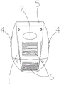
Fig. 1 is the structural representation of the utility model embodiment;
Fig. 2 is the plan structure schematic diagram of the utility model embodiment;
Fig. 3 is the left TV structure schematic diagram of the utility model embodiment.
The specific embodiment
Below in conjunction with accompanying drawing embodiment of the present utility model is elaborated, but the multitude of different ways that the utility model can be defined by the claims and cover is implemented.
Such as Fig. 1, Fig. 2 and shown in Figure 3, the pin-connected panel lamp design of present embodiment, it comprises by the upper shell 1 of rigid plastics moulding and lower house 2, two sides at upper shell 1 and lower house 2 offer semicircle breach, upper shell 1 and lower house 2 are oppositely arranged and are spliced to form one by flexible glue bar 3, that is: the lamp housing main body; At this moment, upper shell 1 can form relative axis hole 4 with breach on the lower house 2, in order to lamp body is fixed rotation; Simultaneously, because the cross section of flexible glue bar 3 is " worker " font, not only can also be conducive to splice the sealing in slit with upper shell 1 and lower house 2 good being stitched together, reach the effect of water proof and dust proof; The dismountable lampshade tight loop 5 that is connected with the rigid plastics moulding of front end (that is: the front end of the lamp housing main body that forms after both splicings are finished) at upper shell 1 and lower house 2.
According to the structural design situation of reality, the version of upper shell 1 and lower house 2 can be identical, is oppositely arranged to form the housing of hollow, also can adopt close or different version.For strengthening the heat dispersion of lamp body, on the interarea of upper shell 1 and lower house 2, respectively be provided with two shutter type thermal windows 6.
In addition, for strengthening the Practical Performance of lamp housing, on the interarea of upper shell 1 and lower house 2, also be provided with the indicia grooves 7 that makes things convenient for manufacturer to attach LOGO, character pattern sign.
The lamp housing of present embodiment, each building block is independently isolating construction, and it can realize quick-assembling, quick-detachment, rapid-maintenance, each parts can be one-body molded, manufacturing process is simple, effectively reduces production cost, has very strong practicality and market popularization value.
The above only is preferred embodiment of the present utility model; be not so limit claim of the present utility model; every equivalent structure or equivalent flow process conversion that utilizes the utility model specification and accompanying drawing content to do; or directly or indirectly be used in other relevant technical fields, all in like manner be included in the scope of patent protection of the present utility model.
Claims (5)
1. pin-connected panel lamp design, it is characterized in that: it comprises upper shell and lower house, and described upper shell and lower house are spliced to form one by the flexible glue bar, and the cross section of described flexible glue bar is " worker " font;
It also comprises the lampshade tight loop, and described lampshade tight loop is connected in the front end of upper shell and lower house.
2. a kind of pin-connected panel lamp design as claimed in claim 1, it is characterized in that: the structure of described upper shell and lower house is identical, and described upper shell and lower house are oppositely arranged.
3. a kind of pin-connected panel lamp design as claimed in claim 1 or 2 is characterized in that: be provided with the shutter type thermal window on the interarea of described upper shell and lower house.
4. a kind of pin-connected panel lamp design as claimed in claim 1 or 2 is characterized in that: also be provided with indicia grooves on the interarea of described upper shell and lower house.
5. a kind of pin-connected panel lamp design as claimed in claim 1, it is characterized in that: described upper shell, lower house and lampshade tight loop are rigid plastics.
Priority Applications (1)
| Application Number | Priority Date | Filing Date | Title |
|---|---|---|---|
| CN2013202653501U CN203240510U (en) | 2013-05-16 | 2013-05-16 | Split-mounting type lamp shell structure |
Applications Claiming Priority (1)
| Application Number | Priority Date | Filing Date | Title |
|---|---|---|---|
| CN2013202653501U CN203240510U (en) | 2013-05-16 | 2013-05-16 | Split-mounting type lamp shell structure |
Publications (1)
| Publication Number | Publication Date |
|---|---|
| CN203240510U true CN203240510U (en) | 2013-10-16 |
Family
ID=49317804
Family Applications (1)
| Application Number | Title | Priority Date | Filing Date |
|---|---|---|---|
| CN2013202653501U Expired - Fee Related CN203240510U (en) | 2013-05-16 | 2013-05-16 | Split-mounting type lamp shell structure |
Country Status (1)
| Country | Link |
|---|---|
| CN (1) | CN203240510U (en) |
Cited By (1)
| Publication number | Priority date | Publication date | Assignee | Title |
|---|---|---|---|---|
| WO2021184946A1 (en) * | 2020-03-17 | 2021-09-23 | 广州市明道文化科技集团股份有限公司 | Waterproof computer moving head spot light having efficient heat dissipation function |
-
2013
- 2013-05-16 CN CN2013202653501U patent/CN203240510U/en not_active Expired - Fee Related
Cited By (1)
| Publication number | Priority date | Publication date | Assignee | Title |
|---|---|---|---|---|
| WO2021184946A1 (en) * | 2020-03-17 | 2021-09-23 | 广州市明道文化科技集团股份有限公司 | Waterproof computer moving head spot light having efficient heat dissipation function |
Similar Documents
| Publication | Publication Date | Title |
|---|---|---|
| CN203240510U (en) | Split-mounting type lamp shell structure | |
| CN202677753U (en) | LED (light-emitting diode) display screen with assembled structure | |
| CN202992702U (en) | Optical module | |
| CN202613158U (en) | Mini light-emitting diode (LED) module | |
| CN206647814U (en) | A kind of the slim-line lamp of no shadow connection | |
| CN210535231U (en) | Spliced LED display screen | |
| CN204706299U (en) | A kind of display lamp box | |
| CN202275571U (en) | Waterproof bracket external member of LED (Light-emitting Diode) outdoor module | |
| CN205388878U (en) | LED display screen splicing structure | |
| CN208587830U (en) | A kind of LED line with water-proof function | |
| CN202791402U (en) | Three-in-one light-emitting diode (LED) module | |
| CN202024154U (en) | LED (light-emitting diode) luminous module | |
| CN215001356U (en) | Double-color-temperature street lamp with intelligent terminal sensing function | |
| CN203442532U (en) | Led lamp | |
| CN205984195U (en) | Colored projection bill -board | |
| CN203406024U (en) | Full-color light-emitting module assembly using light-emitting diodes | |
| CN213394739U (en) | Novel corner line lamp | |
| CN204943378U (en) | A kind of injection moulding LED module with water-repellent lens | |
| CN202584598U (en) | Waterproof LED (Light-Emitting Diode) outdoor structure | |
| CN203689868U (en) | Ultra-thin LED light box capable of adjusting light and color temperature | |
| CN203431564U (en) | Lamp tube structure facilitating replacement of power supplies | |
| CN214275559U (en) | Solar module street lamp | |
| CN211237608U (en) | Right-angle mask and 90-degree LED display screen combination | |
| CN202248276U (en) | Adjustable supporting rod provided with guy cables and used for daylighting roof | |
| CN210777629U (en) | Portable ultrathin LED strip color screen |
Legal Events
| Date | Code | Title | Description |
|---|---|---|---|
| C14 | Grant of patent or utility model | ||
| GR01 | Patent grant | ||
| C41 | Transfer of patent application or patent right or utility model | ||
| TR01 | Transfer of patent right |
Effective date of registration: 20160412 Address after: The heart of the village street Shijing Kau Baiyun District of Guangzhou City, Guangdong province 510000 five second Industrial Zone No. 5 self agency Patentee after: Guangzhou Meishuo Lighting Co. Ltd. Address before: 518000, No. 1, Southern China Avenue, Pinghu Town, Longgang District, Guangdong, Shenzhen Patentee before: Lin Feng |
|
| CF01 | Termination of patent right due to non-payment of annual fee | ||
| CF01 | Termination of patent right due to non-payment of annual fee |
Granted publication date: 20131016 Termination date: 20170516 |