Hollow brick for roof temperature regulation
Technical Field
The invention relates to a part of a combined roof ventilation and temperature adjustment structure, in particular to a hollow brick for roof temperature adjustment.
Background
Referring to fig. 1 and 2, a conventional insulating brick 1 for a roof includes a body 11, and a top plate 12 covering the body 11 and made of a porous material. The body 11 includes a bottom wall 110, a peripheral wall 111 extending from the periphery of the bottom wall 110 and defining an inner space 100 together with the bottom wall 110, a plurality of partition boards 112 disposed in the inner space 100 and dividing the inner space 100 into a plurality of partitions 101, and a plurality of ventilation slots 113 disposed at intervals and recessed outside the peripheral wall 111 and extending along the longitudinal direction.
The heat insulation bricks 1 can be abutted against each other to form a roof heat insulation structure, and air flow can pass through the holes of the top plate 12 through the ventilation characteristic of the porous material of the top plate 12, so that the ventilation groove 113 can be communicated with the outside, and a ventilation effect is formed to avoid heat energy accumulation. However, since the ventilation effect of the insulating bricks 1 depends only on the longitudinal path, in the case where the insulating bricks 1 are laterally abutted against each other, if there is no lateral ventilation path, the heat energy may be accumulated, and it is difficult to achieve sufficient ventilation, heat dissipation, and heat insulation effects.
In addition, when the heat insulation brick 1 is placed on the ground 199, since the bottom wall 110 is directly attached to the ground 199, if water accumulates on the ground 199 due to rain, the water may penetrate into a small gap between the bottom wall 110 and the ground 199. Compared with accumulated water directly exposed to the outside, water permeating into small gaps is difficult to directly evaporate and cannot be irradiated by sunlight, and besides the problem of pure accumulated water, an environment which cannot be sterilized by sunlight irradiation can also form a hotbed for breeding bacteria or make moss grow carelessly for a long time, so that certain environmental sanitation problem is generated. Moreover, if the bottom wall 110 is exposed to accumulated water for a long time, it may cause structural damage, which may affect the safety of the constructed roof insulation structure.
Disclosure of Invention
The invention aims to provide a hollow brick for roof temperature regulation, which can avoid water accumulation and achieve good ventilation, heat insulation and heat dissipation effects.
The invention relates to a hollow brick for roof temperature regulation, which comprises a bottom wall extending along the transverse direction, two side walls spaced along the transverse direction and extending from the bottom wall in the same direction, a plurality of vertical walls extending from the bottom wall between the side walls in the same direction as the side walls, a top cover connected to one side of the side walls and the vertical walls opposite to the bottom wall, and a plurality of foot materials spaced from each other and extending from the bottom wall in the direction opposite to the side walls.
Wherein, the top cover, the bottom wall, the side wall and the vertical wall jointly define a plurality of through culverts. And the two adjacent foot materials and the bottom wall define a through channel together.
The object of the present invention and the technical problems solved thereby can be further achieved by the following technical measures.
Preferably, the roof temperature-adjusting hollow block further comprises two side brackets extending from the bottom wall in a direction away from each other.
Preferably, the hollow block for regulating the temperature of the roof comprises two vertical walls, wherein the bottom wall, the two side walls and the two vertical walls together define three culverts.
Preferably, the roof temperature-adjusting hollow block further comprises two inner brackets extending from the vertical wall toward the side wall in directions away from each other.
Preferably, the roof temperature-adjusting hollow block further comprises two inner brackets respectively connected between the vertical wall and the side wall.
Preferably, the roof temperature-adjusting hollow brick comprises four footings.
The invention has the beneficial effects that: the culvert and the through channel which are transversely communicated can generate transverse airflow flow, and the temperature and the heat are reduced and insulated through the airflow flow, so that good ventilation, heat insulation and heat dissipation effects are achieved; after a plurality of hollow bricks for roof temperature regulation are constructed into a roof ventilation temperature regulation structure, the foot materials can enable the bottom wall of each hollow brick to be spaced from the ground, and the characteristic that airflow circulates in the through channel is utilized to accelerate the evaporation and the dissipation of moisture between the bottom wall and the ground, so that the aim of avoiding water accumulation is effectively fulfilled.
Drawings
FIG. 1 is an exploded perspective view illustrating a conventional insulating brick for a roof;
FIG. 2 is a schematic sectional view illustrating a case where a plurality of the heat insulating bricks for roof are assembled to form a roof heat insulating structure, and disadvantages of the heat insulating bricks;
FIG. 3 is a perspective view illustrating a first embodiment of the roofing air brick of the present invention;
FIG. 4 is a schematic view illustrating the effect of using a plurality of footings of the first embodiment after the first embodiment is used to construct a roof ventilation and temperature regulation structure; and
fig. 5 is a perspective view illustrating a second embodiment of the air brick for roof temperature adjustment according to the present invention.
Detailed Description
The present invention will be described in detail below with reference to the accompanying drawings and examples.
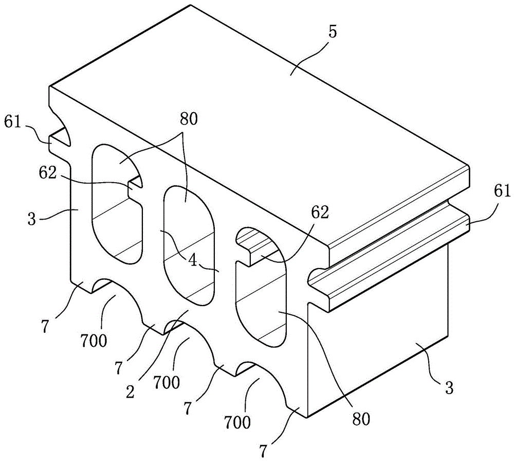
Referring to fig. 3, a first embodiment of the present invention, a hollow block for roof temperature adjustment, comprises a bottom wall 2 extending along a transverse direction, two side walls 3 spaced along the transverse direction and extending in the same direction from the bottom wall 2, two vertical walls 4 extending in the same direction as the side walls 3 from the bottom wall 2 to the side walls 3, a top cover 5 connected to the side walls 3 and the vertical walls 4 opposite to the bottom wall 2, two side brackets 61 extending from the side walls 3 in directions away from each other, two inner brackets 62 extending from the vertical walls 4 in directions away from each other toward the side walls 3, and four footings 7 spaced from each other and extending from the bottom wall 2 in directions opposite to the side walls 3.
The top cover 5, the bottom wall 2, the side wall 3, and the standing wall 4 together define three through culverts 80, and two adjacent leg members 7 and the bottom wall 2 together define a through channel 700. That is, a single first embodiment has at least six ventilation paths extending transversely therethrough to allow air flow therethrough. It should be noted that, in the first embodiment, three culverts 80 are formed by using two vertical walls 4, and three through channels 700 are formed by using four footings 7 at intervals, but in actual implementation, the number of the vertical walls 4 and the footings 7 may be adjusted according to the requirement to define a specific number of culverts 80 and through channels 700, and is not limited to the two vertical walls 4 and the four footings 7 of the first embodiment.
Referring to fig. 4 and fig. 3, when the roof ventilation and temperature adjustment structure is constructed using the first embodiment, it is necessary to match a first corrugated board 91 and a second corrugated board 92 made of plastic, overlap the first corrugated board 91 on two adjacent side brackets 61 of the first embodiment facing each other, and match the feature that the culvert 80 on both sides of each first embodiment can be penetrated by a solid structure, so as to position the first corrugated board 91 reliably. In addition, each second wave plate 92 can be installed by using the inner bracket 62 to pass through the central culvert 80 and simultaneously lap-joint the second wave plate 92 on the inner bracket 62 of the same first embodiment. By arranging a plurality of the first embodiment in several arrays and using the corresponding number of the first corrugated boards 91 and the second corrugated boards 92, the roof ventilation and temperature adjustment structure within a desired range can be matched after the configuration is completed.
The ventilation and temperature adjustment structure for the roof, which is formed by combining a plurality of first corrugated boards 91 and second corrugated boards 92 according to the first embodiment, can generate ventilation effect through three culverts 80 and three through channels 700 of each of the first embodiments. In addition, with the configuration of the first wave plate 91 and the second wave plate 92, an additional ventilation path can be formed to match each other to provide a multi-directional ventilation duct, which can reliably circulate regardless of the airflow direction, thereby generating good ventilation, heat dissipation and heat insulation effects. In addition, utilize foot material 7 makes diapire 2 and ground looks interval, can reduce by a wide margin the possibility of diapire 2 direct contact ponding, and in the frequent circulation of air current in under the circumstances of through channel 700, also form good ventilation environment, provide good moisture evaporation condition, naturally be difficult to form ponding between diapire 2 and ground.
Referring to fig. 5, a second embodiment of the roof temperature-adjusting air brick of the present invention is shown, which differs from the first embodiment in that: the second embodiment includes two inner brackets 62 respectively connected between the vertical wall 4 and the side wall 3. That is, the inner bracket 62 of the second embodiment is different from the inner bracket 62 of the first embodiment in the form that each inner bracket 62 is engaged with the corresponding sidewall 3 and the corresponding standing wall 4, so that the overall structural strength of the second embodiment is enhanced. In addition, the second embodiment also illustrates a technical method of properly adjusting the height of the vertical wall 4, such that the longitudinal height of the vertical wall 4 is extended, the spatial configuration of the culvert 80 can be adjusted, the height of the top cover 5 above the ground can be raised, the proper air intake condition can be adjusted according to the height of the surrounding building structure, such as a parapet, so as to ensure that the airflow can reliably enter the culvert 80 with a better height difference, and a certain ventilation, heat dissipation and heat insulation effect can be maintained.