CN1113304A - Apparatus for providing signal communication between the interior and exterior of a pipeline - Google Patents
Apparatus for providing signal communication between the interior and exterior of a pipeline Download PDFInfo
- Publication number
- CN1113304A CN1113304A CN95103242.9A CN95103242A CN1113304A CN 1113304 A CN1113304 A CN 1113304A CN 95103242 A CN95103242 A CN 95103242A CN 1113304 A CN1113304 A CN 1113304A
- Authority
- CN
- China
- Prior art keywords
- stopple
- pipeline
- link
- affluent channel
- outside
- Prior art date
- Legal status (The legal status is an assumption and is not a legal conclusion. Google has not performed a legal analysis and makes no representation as to the accuracy of the status listed.)
- Pending
Links
Images


Classifications
-
- F—MECHANICAL ENGINEERING; LIGHTING; HEATING; WEAPONS; BLASTING
- F16—ENGINEERING ELEMENTS AND UNITS; GENERAL MEASURES FOR PRODUCING AND MAINTAINING EFFECTIVE FUNCTIONING OF MACHINES OR INSTALLATIONS; THERMAL INSULATION IN GENERAL
- F16L—PIPES; JOINTS OR FITTINGS FOR PIPES; SUPPORTS FOR PIPES, CABLES OR PROTECTIVE TUBING; MEANS FOR THERMAL INSULATION IN GENERAL
- F16L55/00—Devices or appurtenances for use in, or in connection with, pipes or pipe systems
- F16L55/10—Means for stopping flow from or in pipes or hoses
- F16L55/11—Plugs
Landscapes
- Engineering & Computer Science (AREA)
- General Engineering & Computer Science (AREA)
- Mechanical Engineering (AREA)
- Pipeline Systems (AREA)
- Pipe Accessories (AREA)
- Laying Of Electric Cables Or Lines Outside (AREA)
Abstract
An apparatus is providing for signal communication between the interior and exterior of a pipeline. A fitting is secured to the external surface of a pipeline, the fitting having a branch opening therein communicating with the pipeline interior. A plug member is sealably positioned in the branch opening, the plug member having a passageway therethrough. At least one conductor is received in the plug member passageway providing an apparatus to conduct an electrical signal from within to the exterior of the pipeline. A potting compound fills the passageway surrounding the conductor to seal the conductor in the plug against the leakage of liquids or gases.
Description
A kind of device for providing between inside and outside the pipeline signal to transmit is provided.Pipeline in use, the signal that obtains its inner case usually is very important.The example of this respect application has: (1) slug signal transmitting apparatus, and this is a kind of device that sends the slug device by the signal of pipeline; (2) corrosion detector, this is a kind of be corroded device of degree of pipeline of surveying and/or measure; (3) the flow through analysis of composition of pipeline, for example analysis of the water content of petroleum products or its proportion; (4) the flow through temperature of liquid or gas of pipeline; (5) pressure in the pipeline; (6) flow velocity of liquid or gas; And (7) comprise the baseline system of the channel that can sell to serial inspection and testing company.
Had at present make lead from one side of pressure-bearing wall the device to the permanent installation of another side.How to run through the pressure isolation plate about lead, please see following U. S. Patent:
1,541, No. 756; 1,851, No. 939; 1,851, No. 940; 3,135, No. 535;
3,314, No. 030; 3,697, No. 089; 3,772, No. 637; 4,267, No. 401;
4,609, No. 209; 5,235, No. 138 and 5,092, No. 375.
On pipeline, use the example of lead to see U. S. Patent the 4th, 691, No. 728 and 4,465, No. 104.
These prior art reference explanation and having narrated make lead from one side of pressure isolation plate the distinct methods to another side.Yet neither one prior art reference is described as providing between inside and outside the pipeline facility that signal transmits and effective method makes the instrument in the pipeline be examined or to change under pipeline has pressure condition.Removing an electric device, no matter it is to transmit in pipeline or the device of received signal, and has under the pressure condition or change its this ability at pipeline, is very important for pipe operations person.This ability can reduce cost, and need reduce pipeline pressure for new or different signal emissions or reception unit are provided, and at this moment will run into the cost problem.Go up from another point of view and say, the invention provides a kind of in the pipeline device of transmission signal, make the pipeline manipulator can arbitrarily check pipe interior frequently, do not need to stop the proper functioning of pipeline.
The present invention is a kind of device for providing between inside and outside the pipeline signal to transmit.A connection piece is fixed on the pipeline external surface, this link have one with pipeline in the affluent channel of UNICOM.This passage can not obtain by boring on tube wall when pipe interior has hydraulic pressure or air pressure.Another kind method also is feasible, exactly when pipeline has pressure for pipeline provides the link that has affluent channel, be often referred to " hot perforate ".Perforate thereon when being in pressure about pipeline is so that the document that is communicated with pipe interior sees also U. S. Patent the 3rd, 614, No. 252.
In example of the present invention, a connection piece is fixed on the pipeline, and this link has an affluent channel that is communicated with pipe interior.The affluent channel of link has drum type inner surface.
One stopple detachably is arranged in the affluent channel of link, is used for being sealed shut passage.The optimum method that seals between stopple outer cylinder surface and the link interior cylindrical surface is that an O type circle is installed in the circular groove of stopple.Stopple must be fixed in the passage, to bear the pressure from pipe interior.Use a plurality of locking members radially to extend forward and can reach this purpose along the affluent channel of link.When locking member axially inwardly was screwed into, the inner of locking member embedded in the groove of stopple.This mechanism can take out stopple by withdrawing from locking member from link.
In the most preferred embodiment of invention, the link that is installed in pipeline external surface and has a cylindrical shape affluent channel forms a big external diameter flange part around affluent channel in the top.Seal stopple with a blind flange then.The circular flange Bolt Connection of blind flange and link.One through hole is arranged on the blind flange, and aforementioned lead therefrom passes.Through hole is sealed by potting compound.
The design that the present invention has a blind flange makes lead have enough length can reel in the space between stopple and the blind flange or overlapping.Blind flange can move and place on one side in case of necessity, and stopple is checked and changed.When the link top seal, blind flange can be used as the first order sealing of pipeline.
By can further understanding the present invention to the description of most preferred embodiment below in conjunction with accompanying drawing.
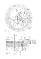
Fig. 1 is mounted in the plan view of the biopsy cavity marker devices of the link on the pipeline.Link has the affluent channel that is communicated with pipeline.One stopple is arranged in the affluent channel of link, and the device that electric connection is provided for the device in the pipeline is housed in this passage.
Fig. 2 is the stereogram that stopple bottom and being used to penetrates the through hole of lead.
Fig. 3 is used for installing or from the scaled down plan view of the device that wherein splits out stopple at link.
Fig. 4 is the main pseudosection of amplification that the expression stopple is positioned at the link top among the affluent channel.One lead passes stopple.The expression stopple is fixed on a kind of device in the link removably.
Fig. 5 is arranged on the plan view of the another kind of form of stopple in the affluent channel of link.There is lead to pass on the stopple.The figure shows a kind of form of radial position plate of using with the stopple lock in place.
Fig. 6 is the amplification profile of 6-6 line among Fig. 5, and this figure has reflected stopple in the link and the device of fixing it more meticulously, and lead passes from stopple, provides the inside and outside electrical signal of pipeline to transmit thus.
With reference to Fig. 1, basic principle of the present invention is described.Being positioned at the pipeline of ground below 12 represents with label 10.The objective of the invention is provides electrical signal to transmit between inside and outside the pipeline 10.In order to realize this purpose, at the outside a connection piece 14 of installing of pipeline.Link 14 has top 14A and bottom 14B.If pipeline 10 is a steel pipe, top 14A and bottom 14B form in this pipeline external welding.Top 14A comprises that one has the integral (type) flange dish 16 of affluent channel 18, and passage is an inner cylindrical surface.
On pipeline 10, process a hole 20 with hole saw.When pipeline has pressure, can use hot perforate technology directly obtain the hole by affluent channel 18, U. S. Patent the 3rd, 614, No. 252 explanations and introduced this technology are here with reference to above-mentioned patent.
One stopple 22 is arranged in the affluent channel 18, and its most preferred embodiment will be introduced below.
The effect of stopple 22 is to be sealed shut affluent channel 18, and this effect is to reach by the O type circle 24 of packing in the circular groove of stopple outer cylinder surface.
One blind flange of removably installing 34 is arranged on the flange plate 16 of link.The through hole that mutual centering is arranged on flange plate 16 and the blind flange 34, bolt 36 pass this Kong Bingyu nut 38 and cooperate, and blind flange 34 is installed on the link 14.Blind flange 34 generally is called " blind " flange, but has a through hole 40 that lead 28 is therefrom passed on it at least.All with the sealed compound sealing, these will be introduced below for through hole 26 on the stopple 22 and the through hole 40 on the blind flange 34.
One seal washer 42 is arranged between the upper end of flange plate 16 and the blind flange 34.The sealing packing ring carries out guaranteeing when fastening sealing between these two flange plate at bolt 36 and nut 38.
As shown in Figure 1, lead 28 curls in the space 44 of stopple 22 upper ends and blind flange 34 downsides.The spare length of lead 28 can be removed blind flange 34, like this can be when checking stopple 22 interfere with guidewire 28 not.In addition, carry out work if desired on stopple 22, the spare length that lead 28 curls in space 44 allows blind flange 34 to move on one side.
Fig. 2 is 22 1 embodiments' of stopple a bottom perspective view, provides a plurality of through holes 26 among the figure, and only express one in Fig. 1.It is multiple conducting wires therefrom to be passed when in pipeline a plurality of instrument being set that a plurality of through holes are provided.
What Fig. 3 represented is a kind of method of removing stopple 22 and prober 30.Stopple more converting mechanism represents that with label 46 it comprises a gate valve 48.Be installed in gate valve on the flange plate 16 and open it, make axle 50 from stopple more converting mechanism 46 extend downwards and engage with stopple 22A.22A pulls out with stopple, and closes gate valve 48.Then, stopple is more removed from gate valve 48 on the top of converting mechanism, can be touched stopple 22A and prober 30 like this, carry out the replacing of stopple self or prober.After the replacing, stopple more is reinstalled in the upside of gate valve 48 in the top of converting mechanism, the prober 30 of stopple and replacing just is installed in the link affluent channel.After stopple 22A put in place, as shown in Figure 4, stopple 22A had been sealed shut affluent channel 18, and the stopple that comprises valve 48 more converting mechanism 46 can be removed, and subsequently blind flange shown in Figure 1 34 is installed on the link 14.
The principle of detachably installing and removing stopple 22A is at U. S. Patent the 3rd, 766, is described in detail in No. 947, here with reference to it.
Fig. 4 is another embodiment's of link a partial enlarged drawing, and this link is with label 14 ' represent.In this embodiment, link 14 ' flange plate 16 ' have the thread locator 52 that extends internally, its end has locking member 54.These locking members can be inserted in the top circular groove 56 on the stopple 22A outer surface.Flange plate 16 ' radially be interval with a plurality of thread locator 52 and locking member 54, when thread locator inside shift-in together, stopple 22A promptly be fixed on affluent channel 18 ' in.When thread locator 52 outwards shifts out, locking member 54 also shifts out from top circular groove 56, can make stopple 22A from affluent channel 18 ' shift out.
In the embodiment shown in fig. 4, the O type circle that is arranged in bottom circular groove 58 provides the contact seal of passage.
The way that makes stopple 22A not only seal but also be fixed on movably in the affluent channel 18 shown in Figure 4 only is an example.The use of locking member 54 and thread locator 52 has more detailed narration in above-mentioned U. S. Patent 3,766,947, here with reference to this patent.
Referring to Fig. 5 and Fig. 6, expression be another embodiment, it is by being that the structure of link self is fixed in the affluent channel of pipe joint stopple fully.As shown in Figure 6, " part that two different inner diameters are arranged on affluent channel, they are the little inner-diameter portion whose 62 of top large diameter part 60 and bottom to the flange plate 16 of link in this structure.The difference of these two section diameters forms a circumferential step 64.On the top large diameter part 60 of affluent channel a circular groove 66 is arranged.
As shown in Figure 5, on the throne for stopple 68 is detachably fixed, at the stopple upper surface two opposed cam- shaped plates 74 and 76 are installed.A diameter through hole 78 of exposing stopple 68 end faces is arranged on the lobe plate 76, on the stopple that the exposes part through hole 80 is arranged, lead 82 therefrom passes.Potting compound 84 is sealed in lead in the through hole 80.
In No. the 4387740th, U. S. Patent, detailed description is arranged as the described method that stopple detachably is arranged in the affluent channel of Fig. 5 and Fig. 6, here with reference to this patent.In this example, increase be through hole 78 these structures on the lobe plate 76, it can pass lead 82 and the work of lobe plate 74 and 76 is not hindered from stopple.When lobe plate radially moved inward mutually, stopple 68 can be located in the affluent channel of link, maybe can be by being removed as shown in Figure 3.By adopting patent 4387740 described cam-flange stopples, this patent provides the principle of this example, when the pipeline pressurized is installed or is changed prober, and the pipe joint or therefrom split out of stopple can being packed into.
Fig. 3 and embodiment illustrated in fig. 4 and Fig. 5 and embodiment illustrated in fig. 6 can use blind flange 34 as shown in Figure 1, prober also as shown in Figure 1 same quadrat method seal connector afterwards is installed.
Fig. 4 and Fig. 5 have represented two different methods that stopple 22 are locked in the link 14.The method of another actual use of the present invention is a machining internal thread on the affluent channel 18 of link 14, the screw thread that the outer round surface processing of stopple 22 is attached thereto, and the stopple in this structure (not shown) is being processed with screw thread with link passage cooperation place.When needs enter link inside, stopple can be backed out.
Claim and specification have been introduced the present invention, and the definition of the term that claim is used is from the use of specification to these terms.The same term of prior art is wideer than the special definition of using here possibly.If the wideer definition of these terms and specifically use between the term here and disagree in the prior art is as the criterion with concrete definition here.
Claims (6)
1, a kind of device for providing between inside and outside the pipeline signal to transmit comprises:
A connection piece is fixed on pipeline external surface, and this link has the affluent channel of inside, a connecting pipe road;
One stopple detachably is arranged in the affluent channel of link, is used for being sealed shut passage, has a through hole on it;
Have at least a lead to pass through hole on the described stopple, in pipeline, pass to outside the pipeline electrical signal;
Sealing has the device of the through hole of described conductor; And
Described stopple detachably is sealed in device in the described passage.
2, the device for providing between inside and outside the pipeline signal to transmit according to claim 1, it is characterized in that, the described link that has affluent channel that is installed on the pipeline, around affluent channel, form a flange plate, and on described link, connect a removable blind flange that is used for sealing affluent channel, form an enclosed space between described stopple and the described blind flange, at least one through hole that lead passes therethrough of permission arranged on the blind flange; With the device that the said lead that passes from blind flange is sealed through hole.
3, the device for providing between inside and outside the pipeline signal to transmit according to claim 2, it is characterized in that, partially folded in the enclosed space of described at least one lead between described stopple and described blind flange, described like this blind flange can be removed from described flange plate, and described stopple is exposed fully.
4, the device for providing between inside and outside the pipeline signal to transmit according to claim 1, it is characterized in that, the interior cylindrical surface of the affluent channel of described link has two different internal diameters, the two forms a circumferential step, two different external diameters of described stopple outer surface form a boss, described boss and the engagement of described circumferential step realize the location of described stopple in described link affluent channel.
5, the device for providing between inside and outside the pipeline signal to transmit according to claim 1 is characterized in that described affluent channel has at least one section to be processed into interior cylindrical surface, the stopple that has circular groove on the outer surface put into wherein and
One cyclic spring packing ring is arranged in the described circular groove.
6, the device for providing between inside and outside the pipeline signal to transmit according to claim 1 comprises: be used for detachably said stopple sealably being fixed on the device that operate the outside at said link of the affluent channel of described link.
Applications Claiming Priority (2)
| Application Number | Priority Date | Filing Date | Title |
|---|---|---|---|
| US204,056 | 1994-03-01 | ||
| US08/204,056 US5450765A (en) | 1994-03-01 | 1994-03-01 | Apparatus for providing signal communication between the interior and exterior of a pipeline |
Publications (1)
| Publication Number | Publication Date |
|---|---|
| CN1113304A true CN1113304A (en) | 1995-12-13 |
Family
ID=22756438
Family Applications (1)
| Application Number | Title | Priority Date | Filing Date |
|---|---|---|---|
| CN95103242.9A Pending CN1113304A (en) | 1994-03-01 | 1995-03-01 | Apparatus for providing signal communication between the interior and exterior of a pipeline |
Country Status (8)
| Country | Link |
|---|---|
| US (1) | US5450765A (en) |
| JP (1) | JPH07332600A (en) |
| CN (1) | CN1113304A (en) |
| AU (1) | AU683124B2 (en) |
| BR (1) | BR9500786A (en) |
| CA (1) | CA2143708A1 (en) |
| PE (1) | PE19096A1 (en) |
| TW (1) | TW286361B (en) |
Cited By (6)
| Publication number | Priority date | Publication date | Assignee | Title |
|---|---|---|---|---|
| CN102182888A (en) * | 2011-05-04 | 2011-09-14 | 同济大学 | Pipe joint with intelligent self-repairing function |
| CN103292109A (en) * | 2012-03-01 | 2013-09-11 | 明和工业株式会社 | Mounting structure and assembling and unassembling device for accessory device in branching pipe of pipeline |
| CN105627024A (en) * | 2016-03-30 | 2016-06-01 | 池州恒生科技发展有限公司 | Pipe repair device assembly |
| CN105627026A (en) * | 2016-03-30 | 2016-06-01 | 池州恒生科技发展有限公司 | Pipe repair device assembly |
| CN114735171A (en) * | 2022-05-05 | 2022-07-12 | 广州大学 | Underwater robot pipeline pressure detection connecting piece |
| CN114811255A (en) * | 2021-04-25 | 2022-07-29 | 四川大唐国际甘孜水电开发有限公司 | Pipeline mouth sealing device for pre-buried pipeline |
Families Citing this family (48)
| Publication number | Priority date | Publication date | Assignee | Title |
|---|---|---|---|---|
| US5760316A (en) * | 1996-10-03 | 1998-06-02 | Niolon, Jr.; Spencer L. | Electrical penetrator apparatus for bulkheads |
| US5844138A (en) * | 1997-03-07 | 1998-12-01 | Veris Industries, Inc. | Humidity sensor |
| US6093886A (en) * | 1997-10-28 | 2000-07-25 | University Of Rochester | Vacuum-tight continuous cable feedthrough device |
| HUP9800248A1 (en) | 1998-02-05 | 1999-12-28 | József Bereznai | Pipe lock automat |
| US5975142A (en) * | 1998-08-10 | 1999-11-02 | Tdw Delaware, Inc. | Removable closure system |
| US6286553B1 (en) * | 2000-09-01 | 2001-09-11 | Tdw Delaware, Inc. | Removable closure system |
| US6543303B1 (en) * | 2000-10-06 | 2003-04-08 | Howard Hilborn | Pressure-retaining disk |
| KR100473859B1 (en) * | 2001-08-24 | 2005-03-08 | 이우각 | Plug for pipe's fitting |
| US6830249B2 (en) * | 2002-04-22 | 2004-12-14 | General Electric Company | Brazeable, multi-lead, low profile sealing fitting and method of installation |
| US7249885B2 (en) * | 2002-10-16 | 2007-07-31 | Clyde Bergemann Gmbh | Heat flux measuring device for pressure pipes, method for producing a measuring device, method for monitoring an operating state of a heat exchanger, heat exchanger and method for measuring a heat flux |
| US7034553B2 (en) * | 2003-12-05 | 2006-04-25 | Prodont, Inc. | Direct resistance measurement corrosion probe |
| US7298279B1 (en) | 2005-05-19 | 2007-11-20 | The Williams Companies, Inc. | Open-ended device monitoring system |
| US7353839B2 (en) * | 2005-05-19 | 2008-04-08 | Tdw Delaware, Inc. | High temperature completion plug |
| AT501879B1 (en) * | 2005-05-24 | 2007-05-15 | Pustelnik Philipp Dipl Ing | ADAPTER PACK FOR A DEVICE FOR CONNECTING PIPES |
| US7226207B2 (en) * | 2005-09-09 | 2007-06-05 | Feldmeier Robert H | Temperature gauge for use with sanitary conduit |
| US7861665B2 (en) * | 2007-05-11 | 2011-01-04 | Tdw Delaware Inc. | Pipeline pig signal with adjustable mounting |
| CA2609619A1 (en) | 2007-09-10 | 2009-03-10 | Veris Industries, Llc | Status indicator |
| CA2609611A1 (en) | 2007-09-10 | 2009-03-10 | Veris Industries, Llc | Split core status indicator |
| CA2609629A1 (en) | 2007-09-10 | 2009-03-10 | Veris Industries, Llc | Current switch with automatic calibration |
| US8212548B2 (en) | 2008-06-02 | 2012-07-03 | Veris Industries, Llc | Branch meter with configurable sensor strip arrangement |
| US8001988B2 (en) * | 2008-06-09 | 2011-08-23 | Tdw Delaware, Inc. | Verifiable closing and locking system of a cylindrical passageway |
| US8421443B2 (en) | 2008-11-21 | 2013-04-16 | Veris Industries, Llc | Branch current monitor with calibration |
| US8421639B2 (en) | 2008-11-21 | 2013-04-16 | Veris Industries, Llc | Branch current monitor with an alarm |
| US9335352B2 (en) | 2009-03-13 | 2016-05-10 | Veris Industries, Llc | Branch circuit monitor power measurement |
| EP2417432B1 (en) * | 2009-04-09 | 2020-02-12 | Schlumberger Technology Corporation | Method and system for detection of fluid invasion in an annular space of flexible pipe |
| US20120192981A1 (en) * | 2011-01-31 | 2012-08-02 | Peter Kruchoski | Lining measurement system for a pipe or other fluid-handling component |
| US9146264B2 (en) | 2011-02-25 | 2015-09-29 | Veris Industries, Llc | Current meter with on board memory |
| US10006948B2 (en) | 2011-02-25 | 2018-06-26 | Veris Industries, Llc | Current meter with voltage awareness |
| US9329996B2 (en) | 2011-04-27 | 2016-05-03 | Veris Industries, Llc | Branch circuit monitor with paging register |
| US9250308B2 (en) | 2011-06-03 | 2016-02-02 | Veris Industries, Llc | Simplified energy meter configuration |
| US8969741B2 (en) | 2011-06-10 | 2015-03-03 | Cooper Technologies Company | Damming device for cable sealing |
| WO2012170859A2 (en) | 2011-06-10 | 2012-12-13 | Cooper Technologies Company | Damming device for cable sealing |
| US9410552B2 (en) | 2011-10-05 | 2016-08-09 | Veris Industries, Llc | Current switch with automatic calibration |
| GB2510427B (en) * | 2013-02-05 | 2018-02-07 | Flakt Woods Ltd | A method and apparatus for encapsulating cables |
| US9728817B2 (en) | 2013-03-14 | 2017-08-08 | Invodane Engineering Ltd. | Apparatus and method for in-line charging of a pipeline tool |
| US9095736B2 (en) | 2013-05-07 | 2015-08-04 | Engineered Corrosion Solutions, Llc | Corrosion monitoring in a fire sprinkler system |
| WO2015147686A1 (en) * | 2014-03-28 | 2015-10-01 | Открытое акционерное общество "Акционерная компания по транспорту нефти "Транснефть" (ОАО "АК "Транснефть") | Method for monitoring the position of above-ground pipelines in permafrost conditions |
| US20160097559A1 (en) * | 2014-10-02 | 2016-04-07 | Richard Dean McFarland | Access port |
| US10274572B2 (en) | 2015-12-28 | 2019-04-30 | Veris Industries, Llc | Calibration system for a power meter |
| US10371721B2 (en) | 2015-12-28 | 2019-08-06 | Veris Industries, Llc | Configuration system for a power meter |
| US10408911B2 (en) | 2015-12-28 | 2019-09-10 | Veris Industries, Llc | Network configurable system for a power meter |
| US10371730B2 (en) | 2015-12-28 | 2019-08-06 | Veris Industries, Llc | Branch current monitor with client level access |
| US11215650B2 (en) | 2017-02-28 | 2022-01-04 | Veris Industries, Llc | Phase aligned branch energy meter |
| US11193958B2 (en) | 2017-03-03 | 2021-12-07 | Veris Industries, Llc | Non-contact voltage sensor |
| US10295101B2 (en) * | 2017-04-20 | 2019-05-21 | Total Piping Solutions, Inc. | Push plug type line stop branch assembly |
| US10705126B2 (en) | 2017-05-19 | 2020-07-07 | Veris Industries, Llc | Energy metering with temperature monitoring |
| CN112197180B (en) * | 2020-10-16 | 2022-06-03 | 宁波耀通管阀科技有限公司 | Gas pipe fitting leak protection structure |
| US11619322B1 (en) * | 2021-08-31 | 2023-04-04 | Jason Russell | Clean-out cap locator |
Family Cites Families (19)
| Publication number | Priority date | Publication date | Assignee | Title |
|---|---|---|---|---|
| US1541756A (en) * | 1924-01-17 | 1925-06-09 | Lancaster Tire And Rubber Comp | Closure for conduits |
| US1851939A (en) * | 1929-10-30 | 1932-03-29 | Orr H Williams | Closure for conduits |
| US1851940A (en) * | 1929-11-13 | 1932-03-29 | Orr H Williams | Closure for conduits and the like |
| US3135535A (en) * | 1961-09-27 | 1964-06-02 | Ralph H Shepard | Boot and plug closure |
| US3314030A (en) * | 1963-10-31 | 1967-04-11 | Central Transformer Corp | Transformers with leak- and coronafree direct electrical connections |
| US3441662A (en) * | 1967-05-02 | 1969-04-29 | Mc Donnell Douglas Corp | Feed-through seal |
| US3697089A (en) * | 1970-12-30 | 1972-10-10 | Joseph Michael Jacisin | High-pressure packing gland |
| US3772637A (en) * | 1972-02-16 | 1973-11-13 | Amp Inc | Device for sealing electrical connectors |
| US3766947A (en) * | 1972-06-05 | 1973-10-23 | Williamson Inc T | Fluid tight closure |
| US4267401A (en) * | 1978-07-03 | 1981-05-12 | Wilkinson William L | Seal plug |
| US4313030A (en) * | 1979-02-26 | 1982-01-26 | Bunker Ramo Corporation | Electrical penetration apparatus and method of making same |
| US4465104A (en) * | 1981-02-27 | 1984-08-14 | Hughes Tool Company | Pressure energized pipeline plug |
| US4387740A (en) * | 1981-05-15 | 1983-06-14 | T. D. Williamson, Inc. | Cam-flange |
| JPS5839216A (en) * | 1981-08-31 | 1983-03-07 | アイシン・エィ・ダブリュ株式会社 | Method and device for coupling and sealing wire in hydraulic equipment |
| US4691728A (en) * | 1986-05-28 | 1987-09-08 | Cherne Industries, Inc. | Electronic test and seal apparatus and method |
| US4693278A (en) * | 1986-11-10 | 1987-09-15 | T. D. Williamson, Inc. | Safety closure member |
| US5092375A (en) * | 1990-07-25 | 1992-03-03 | Landers Phillip G | Liquid barrier system |
| JP2766558B2 (en) * | 1991-02-14 | 1998-06-18 | 矢崎総業株式会社 | Electric wire holding case for preventing oil leakage |
| US5235138A (en) * | 1991-06-24 | 1993-08-10 | Shah Jagdish H | Penetration plug for pressure vessels |
-
1994
- 1994-03-01 US US08/204,056 patent/US5450765A/en not_active Expired - Fee Related
-
1995
- 1995-03-01 PE PE1995263011A patent/PE19096A1/en not_active Application Discontinuation
- 1995-03-01 BR BR9500786A patent/BR9500786A/en not_active Application Discontinuation
- 1995-03-01 JP JP7042138A patent/JPH07332600A/en active Pending
- 1995-03-01 CA CA002143708A patent/CA2143708A1/en not_active Abandoned
- 1995-03-01 CN CN95103242.9A patent/CN1113304A/en active Pending
- 1995-03-01 AU AU13580/95A patent/AU683124B2/en not_active Expired - Fee Related
- 1995-03-02 TW TW084101975A patent/TW286361B/zh active
Cited By (8)
| Publication number | Priority date | Publication date | Assignee | Title |
|---|---|---|---|---|
| CN102182888A (en) * | 2011-05-04 | 2011-09-14 | 同济大学 | Pipe joint with intelligent self-repairing function |
| CN102182888B (en) * | 2011-05-04 | 2012-06-06 | 同济大学 | Pipe joint with intelligent self-repairing function |
| CN103292109A (en) * | 2012-03-01 | 2013-09-11 | 明和工业株式会社 | Mounting structure and assembling and unassembling device for accessory device in branching pipe of pipeline |
| CN105627024A (en) * | 2016-03-30 | 2016-06-01 | 池州恒生科技发展有限公司 | Pipe repair device assembly |
| CN105627026A (en) * | 2016-03-30 | 2016-06-01 | 池州恒生科技发展有限公司 | Pipe repair device assembly |
| CN114811255A (en) * | 2021-04-25 | 2022-07-29 | 四川大唐国际甘孜水电开发有限公司 | Pipeline mouth sealing device for pre-buried pipeline |
| CN114811255B (en) * | 2021-04-25 | 2024-05-24 | 四川大唐国际甘孜水电开发有限公司 | Pipeline port sealing device for embedded pipeline |
| CN114735171A (en) * | 2022-05-05 | 2022-07-12 | 广州大学 | Underwater robot pipeline pressure detection connecting piece |
Also Published As
| Publication number | Publication date |
|---|---|
| JPH07332600A (en) | 1995-12-22 |
| CA2143708A1 (en) | 1995-09-02 |
| US5450765A (en) | 1995-09-19 |
| TW286361B (en) | 1996-09-21 |
| AU1358095A (en) | 1995-09-07 |
| AU683124B2 (en) | 1997-10-30 |
| PE19096A1 (en) | 1996-06-20 |
| BR9500786A (en) | 1995-11-28 |
Similar Documents
| Publication | Publication Date | Title |
|---|---|---|
| CN1113304A (en) | Apparatus for providing signal communication between the interior and exterior of a pipeline | |
| US4019371A (en) | Apparatus and method for externally testing conduit connections | |
| EP0857297B1 (en) | A device for detecting leakage in flange joints | |
| US6299216B1 (en) | Joints | |
| CA1176189A (en) | Pipe tester plug | |
| US5295760A (en) | Testable bulkhead | |
| US11680483B2 (en) | Plug assembly for positioning within a passageway of a wellhead component | |
| CA1045206A (en) | Flush mounted probe for corrosion testing | |
| US8220839B2 (en) | Pipe insert | |
| US20070051164A1 (en) | Method and Apparatus for Verifying the Integrity of a Joint Seal | |
| CN1225733A (en) | Corrosion monitoring system | |
| US7004470B2 (en) | Device for a pipe flange seal | |
| CA1312557C (en) | Test plug for flanged pipes | |
| USRE30311E (en) | Apparatus and method for externally testing conduit connections | |
| CA1221251A (en) | Pipe testing tool | |
| AU2005218073B2 (en) | Pipe insert | |
| US6000290A (en) | Quick-connect industrial process sensor | |
| US20230175625A1 (en) | An improved connector for a subsea drilling riser | |
| US20240030650A1 (en) | Connector assembly | |
| US20240035624A1 (en) | Double sealed pressure containment assembly | |
| AU736059C (en) | Joints | |
| CA2299954C (en) | Apparatus for maximizing tubular penetrations | |
| BR202022020558U2 (en) | VERTICAL CONNECTION MODULE (MCV) HUB PLUG | |
| JPS6212421B2 (en) | ||
| Daoud et al. | Cable seal for submerged enclosures |
Legal Events
| Date | Code | Title | Description |
|---|---|---|---|
| C06 | Publication | ||
| PB01 | Publication | ||
| C10 | Entry into substantive examination | ||
| SE01 | Entry into force of request for substantive examination | ||
| C01 | Deemed withdrawal of patent application (patent law 1993) | ||
| WD01 | Invention patent application deemed withdrawn after publication |