US1851939A - Closure for conduits - Google Patents
Closure for conduits Download PDFInfo
- Publication number
- US1851939A US1851939A US403458A US40345829A US1851939A US 1851939 A US1851939 A US 1851939A US 403458 A US403458 A US 403458A US 40345829 A US40345829 A US 40345829A US 1851939 A US1851939 A US 1851939A
- Authority
- US
- United States
- Prior art keywords
- septum
- conduit
- conductor
- cable
- parts
- Prior art date
- Legal status (The legal status is an assumption and is not a legal conclusion. Google has not performed a legal analysis and makes no representation as to the accuracy of the status listed.)
- Expired - Lifetime
Links
- 239000004020 conductor Substances 0.000 description 30
- 230000006835 compression Effects 0.000 description 13
- 238000007906 compression Methods 0.000 description 13
- 239000007789 gas Substances 0.000 description 4
- 230000000295 complement effect Effects 0.000 description 3
- 238000003780 insertion Methods 0.000 description 3
- 230000037431 insertion Effects 0.000 description 3
- 239000000463 material Substances 0.000 description 2
- BFPSDSIWYFKGBC-UHFFFAOYSA-N chlorotrianisene Chemical compound C1=CC(OC)=CC=C1C(Cl)=C(C=1C=CC(OC)=CC=1)C1=CC=C(OC)C=C1 BFPSDSIWYFKGBC-UHFFFAOYSA-N 0.000 description 1
- 150000001875 compounds Chemical class 0.000 description 1
- 239000012530 fluid Substances 0.000 description 1
- 230000001473 noxious effect Effects 0.000 description 1
- 238000012856 packing Methods 0.000 description 1
- 238000003825 pressing Methods 0.000 description 1
- 230000002040 relaxant effect Effects 0.000 description 1
- 239000012858 resilient material Substances 0.000 description 1
Images
Classifications
-
- H—ELECTRICITY
- H02—GENERATION; CONVERSION OR DISTRIBUTION OF ELECTRIC POWER
- H02G—INSTALLATION OF ELECTRIC CABLES OR LINES, OR OF COMBINED OPTICAL AND ELECTRIC CABLES OR LINES
- H02G9/00—Installations of electric cables or lines in or on the ground or water
- H02G9/06—Installations of electric cables or lines in or on the ground or water in underground tubes or conduits; Tubes or conduits therefor
Definitions
- Conduitsl for leading electric conductors into houses7 building and other structures frequently constitute the means for conveying eXplosiveor noxious gasesinto such structures thereby endangering the health, lives and limbs of the occupants.
- Means have been proposed for plugging such conduits to prevent the passage of gases with a septum provided With holes for the electric conductors.
- the primary object of the present invention is to provideimproved means for fac1litating the insertion ofthe electrical conductors in thev hole of the septum whereby the conduit may quickly and economically be plugged- Without cutting the conductor and such gases satisfactorily prevented from pass ing into the building.
- the invention can be utilized at any point in a conduit Where it is desirable to arrest orprevent the HOW of any Huid from the conduit or from one point to another therein.y
- Figure l1 is a longitudinal section of the terminal of a cable conduit with the-invention applied thereto.
- Fig. 2' is a side elevation of the compressibleseptum or plug.
- Fig 3 is an edge view of the same.
- Fig. 4 is an edge view of a pair of the septums.
- Fig. 5 is an elevation ofthe inner sides of a group of the compressible members.
- Fig. 6 is an edge view of the same.
- FIG. 7 designates a. fraction of a conduit at its end said conduit being of the usual material and as it appears terminating at the inner side of the cellar Wall ofthe cellar of a building.
- 8 designates the usual cables containing the electrical conductors.
- 9 designates the septum or plug composed of tivo parts of suitable compressible or resilient material'such for example as rubber or a compound thereof adapted to serve as a packing to resist the pressure and passage of fluid.
- the parts of the septum are each shown as of circular outline of plano-concave form and as provided With Serial No. 403,458.
- the tivo parts of the septum can be made identical with eachother.
- Each part of the septum is cut from the rim inward With a slit 1l to each of the cable receiving openings l0, said slit being preferably at an ineline to-the plane of theseptum so that when pressure is applied to the septum the faces of the slit Will bepressed against each other.
- the said slits are each offset from a radius passing through the center of the cable receiving opening and the parts ofthe septum are identical these slits do not coincide longitudinally in the conductor andV therefore aid in preventing the passage of gases.
- rlhe septum is also provided with bolt holes 15a for screw bolts l2v for applying pressure as hereinafter described.
- the tivo parts of the septum will be placed together with the concave faces opposed to-eachr other, hence when pressure is applied to the opposite plane faces the rim Will be bulged radially tovvardl the Wall of the conduit and therefore prevent the passage of gases.
- the compression members7 designates the compression members7 these being of sector-like form and each provided With arcuate recesses let in its straight dges so as to form7 when assembled against the plane face of thecoincided parts of the septum a circular-like opening to fit around the cables as best shown in Fig. 1.
- These compression sectors are eachprovided With a bolt hole l5 for the passage of the aforesaid bolt l2, the holes of the inner compression members being threaded to receive the thread ed end of the bolt.
- the inner faces of the compression members can be made With Vshaped ribs such as at 16 and 17 to bite into the septum.
- the cables can be inserted into their holes laterally by spreading apart the septum at its'split portion, and before the sector compression plates areapplied to the opposite sides of the septum. rI his avoids cutting the cables.
- the three bolts are further turned to tighten them up and expand the ductor and a through slit transversely of the Y septum leading from the rim of the septum rim of the septum into close contact with the inner wall of the conduit and the walls of the cable openings around the cables.
- the septum can be easily removed from the conduit by simply loosening the three bolts thereby relaxing the grip of the septum in the conduit.
- Means for plugging a conduit for an electrical or other conductor comprising a compressible septum for the conduit, said septum provided with an opening for the conto the conductor opening thereby permitting the lateral insertion of the conductor to said opening.
- Y Vv2. Means for plugging a conduit for an electrical or other conductor comprising a compressible septum for the conduit, said septum provided with an opening for the conductor and a through slit transversely of the septum and inclined to the plane of the septum leading from the rim of the septum to the conductor opening thereby permitting the lateral insertion of the conductor to said opening.
- llelileans for plugging a conduit for an electrical or other conductor comprising a compressible septum for the conduit, said septum provided with van opening for the conductor, and a through slit transversely of the septum leading from the rim ofV the septum to the conductor receiving opening, and a compressible member for the face of the septum composed of a plurality of sector-like parts with complementary recesses fitting around they conductor and means for drawing said parts against the septum.
- a compressible member for the face of the septum composed of a plurality of parts with complementary recesses fitting around the body of the septum and leading from the ⁇ rim Yof the septum to the conductor receiving opening, and a compression member for the V.tace of the septum litting around the conductor and means for drawing said parts against the septum, said compression member provided vwithV projecting ribs to bite into the septum.
- Means for plugging a conduit for an electrical or other conductor comprising a .compressibleseptum for 4the conduit, said septum provided with an opening for the conductor, and a through slit transverse the rim of the septum and leading from the rim of Athe septum to the conductor receiving opening, and a compression member for the face of the septum fitting around the conductor and means for drawing said parts against the septum, said compression member provided with projecting ribs to bite into the septum to expand the material of the septum outwardly against the conduit and inwardly against the cable.
- Means for plugging a conduit for -an electrical or other conductor comprising a septum adapted to expand radially when subjected to compression, and having cableopenings provided with transverse entranceways completely dividing the septum from said cable openings to the rim thereof adapted to permit of the entrance of the cable in a direction transverse to the axis of the cable.
- Means for vplugging a conduit for an electrical or other conductor comprising the combination with an eXpansible septum adapted to fit within a conduit, and having V cable-openings completely dividing the septum from the cable openings to the rim of the septum adapted to receive cables in a direction at anvangle to the axis of the cables, and compression members adapted when under pressure to cause the septum to expand.
- Means'for plugging a conduit vfor an electrical or other .conductor comprisingthe combination with a septum adapted to eX- pand radially when subjected to compres-V sion, and having cable-openings provided with entrance-ways completely dividing the septum from the cable openingtothe rimof the septum adapted to permit of the entrance of the cable in a direction transverse to the axis of the cable, and compression Vmembers adapted when under pressure to compress the septum to cause the septum to expand radially.
Landscapes
- Infusion, Injection, And Reservoir Apparatuses (AREA)
Description
Ma 29, O. H, WILLIAMS CLOSURE FOR CONDUI TS Filed Oct. 30, 1929 nventor @RR H.WLL!AMS A@ Gtforncg J lilo-.tentati lidar. 29, 1932 rare F'FQE OBR H. WILLIAMS, OF COLUMBUS, OHIO CLOSURE FOR CONDUITS ApplicationV filed October 30, 1929.
Conduitsl for leading electric conductors into houses7 building and other structures frequently constitute the means for conveying eXplosiveor noxious gasesinto such structures thereby endangering the health, lives and limbs of the occupants. Means have been proposed for plugging such conduits to prevent the passage of gases with a septum provided With holes for the electric conductors.
The primary object of the present invention is to provideimproved means for fac1litating the insertion ofthe electrical conductors in thev hole of the septum whereby the conduit may quickly and economically be plugged- Without cutting the conductor and such gases satisfactorily prevented from pass ing into the building. The invention can be utilized at any point in a conduit Where it is desirable to arrest orprevent the HOW of any Huid from the conduit or from one point to another therein.y
The invention is embodied in the example herein shown and described, the features of novelty being finally claimed.
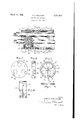
In the accompanying drawings- Figure l1 is a longitudinal section of the terminal of a cable conduit with the-invention applied thereto.
Fig. 2'is a side elevation of the compressibleseptum or plug.
Fig 3 is an edge view of the same.
Fig. 4 is an edge view of a pair of the septums.
Fig. 5 is an elevation ofthe inner sides of a group of the compressible members.
Fig. 6 is an edge view of the same.
In the views 7 designates a. fraction of a conduit at its end said conduit being of the usual material and as it appears terminating at the inner side of the cellar Wall ofthe cellar of a building. 8 designates the usual cables containing the electrical conductors. 9 designates the septum or plug composed of tivo parts of suitable compressible or resilient material'such for example as rubber or a compound thereof adapted to serve as a packing to resist the pressure and passage of fluid.
In the present instance the parts of the septum are each shown as of circular outline of plano-concave form and as provided With Serial No. 403,458.
three transverse openings l0 equally spaced from each other and from the center of the septum. The tivo parts of the septum can be made identical with eachother. Each part of the septum is cut from the rim inward With a slit 1l to each of the cable receiving openings l0, said slit being preferably at an ineline to-the plane of theseptum so that when pressure is applied to the septum the faces of the slit Will bepressed against each other. When the said slits are each offset from a radius passing through the center of the cable receiving opening and the parts ofthe septum are identical these slits do not coincide longitudinally in the conductor andV therefore aid in preventing the passage of gases. rlhe septum is also provided with bolt holes 15a for screw bolts l2v for applying pressure as hereinafter described.
In practice the tivo parts of the septum will be placed together with the concave faces opposed to-eachr other, hence when pressure is applied to the opposite plane faces the rim Will be bulged radially tovvardl the Wall of the conduit and therefore prevent the passage of gases.
13 designates the compression members7 these being of sector-like form and each provided With arcuate recesses let in its straight dges so as to form7 when assembled against the plane face of thecoincided parts of the septum a circular-like opening to fit around the cables as best shown in Fig. 1. These compression sectors are eachprovided With a bolt hole l5 for the passage of the aforesaid bolt l2, the holes of the inner compression members being threaded to receive the thread ed end of the bolt. If desired the inner faces of the compression members can be made With Vshaped ribs such as at 16 and 17 to bite into the septum.
Among the advantages of this improvement is that the cables can be inserted into their holes laterally by spreading apart the septum at its'split portion, and before the sector compression plates areapplied to the opposite sides of the septum. rI his avoids cutting the cables. After the assembled parts are shoved ifnto the conduit the three bolts are further turned to tighten them up and expand the ductor and a through slit transversely of the Y septum leading from the rim of the septum rim of the septum into close contact with the inner wall of the conduit and the walls of the cable openings around the cables. The septum can be easily removed from the conduit by simply loosening the three bolts thereby relaxing the grip of the septum in the conduit.
The forms of `the parts can be changed without departing from thegist of the invention as claimed.
`What I claim is:
l. Means for plugging a conduit for an electrical or other conductor comprising a compressible septum for the conduit, said septum provided with an opening for the conto the conductor opening thereby permitting the lateral insertion of the conductor to said opening. Y Vv2. Means for plugging a conduit for an electrical or other conductor comprising a compressible septum for the conduit, said septum provided with an opening for the conductor and a through slit transversely of the septum and inclined to the plane of the septum leading from the rim of the septum to the conductor opening thereby permitting the lateral insertion of the conductor to said opening. Y
3.,.Means ior plugging a conduit for an electrical or other conductor comprising a compressible septum for the conduit, said septum provided with an opening for the conductoigand a through slit transversely of the .septum leading from the rim of the septum to the conductor receiving opening, and a compression member for the face of the septum composed of la plurality of parts with ,complementary recesses fitting around the conductor and means for drawing said parts against the septum.
llelileans for plugging a conduit for an electrical or other conductor comprising a compressible septum for the conduit, said septum provided with van opening for the conductor, and a through slit transversely of the septum leading from the rim ofV the septum to the conductor receiving opening, and a compressible member for the face of the septum composed of a plurality of sector-like parts with complementary recesses fitting around they conductor and means for drawing said parts against the septum.
of and inclined to the plane of the septum and leading from therrimof the septum to theV conductor receiving opening, and a compressible member for the face of the septum composed of a plurality of parts with complementary recesses fitting around the body of the septum and leading from the` rim Yof the septum to the conductor receiving opening, and a compression member for the V.tace of the septum litting around the conductor and means for drawing said parts against the septum, said compression member provided vwithV projecting ribs to bite into the septum. i
'7. Means for plugging a conduit for an electrical or other conductor comprising a .compressibleseptum for 4the conduit, said septum provided with an opening for the conductor, and a through slit transverse the rim of the septum and leading from the rim of Athe septum to the conductor receiving opening, and a compression member for the face of the septum fitting around the conductor and means for drawing said parts against the septum, said compression member provided with projecting ribs to bite into the septum to expand the material of the septum outwardly against the conduit and inwardly against the cable. c i
8. Means for plugging a conduit for -an electrical or other conductor comprising a septum adapted to expand radially when subjected to compression, and having cableopenings provided with transverse entranceways completely dividing the septum from said cable openings to the rim thereof adapted to permit of the entrance of the cable in a direction transverse to the axis of the cable.
9. Means for vplugging a conduit for an electrical or other conductor comprising the combination with an eXpansible septum adapted to fit within a conduit, and having V cable-openings completely dividing the septum from the cable openings to the rim of the septum adapted to receive cables in a direction at anvangle to the axis of the cables, and compression members adapted when under pressure to cause the septum to expand.
10. Means'for plugging a conduit vfor an electrical or other .conductor comprisingthe combination with a septum adapted to eX- pand radially when subjected to compres-V sion, and having cable-openings provided with entrance-ways completely dividing the septum from the cable openingtothe rimof the septum adapted to permit of the entrance of the cable in a direction transverse to the axis of the cable, and compression Vmembers adapted when under pressure to compress the septum to cause the septum to expand radially.
i OBR H. WILLIAMS.
Priority Applications (1)
| Application Number | Priority Date | Filing Date | Title |
|---|---|---|---|
| US403458A US1851939A (en) | 1929-10-30 | 1929-10-30 | Closure for conduits |
Applications Claiming Priority (1)
| Application Number | Priority Date | Filing Date | Title |
|---|---|---|---|
| US403458A US1851939A (en) | 1929-10-30 | 1929-10-30 | Closure for conduits |
Publications (1)
| Publication Number | Publication Date |
|---|---|
| US1851939A true US1851939A (en) | 1932-03-29 |
Family
ID=23595854
Family Applications (1)
| Application Number | Title | Priority Date | Filing Date |
|---|---|---|---|
| US403458A Expired - Lifetime US1851939A (en) | 1929-10-30 | 1929-10-30 | Closure for conduits |
Country Status (1)
| Country | Link |
|---|---|
| US (1) | US1851939A (en) |
Cited By (18)
| Publication number | Priority date | Publication date | Assignee | Title |
|---|---|---|---|---|
| US2661120A (en) * | 1950-05-25 | 1953-12-01 | Joseph F G Miller | Closure plug for a tubular casing |
| US2750487A (en) * | 1952-08-12 | 1956-06-12 | Turbine Equipment Company | Electric heater |
| US2886627A (en) * | 1954-01-12 | 1959-05-12 | Norddeutsche Seckabelwerke Ag | Plug arrangement for coaxial cables |
| US3045830A (en) * | 1958-04-29 | 1962-07-24 | Fulton Leota Williamson | Liquid dispersion separating device |
| US3751578A (en) * | 1971-04-08 | 1973-08-07 | Siemens Ag | Metal-clad three-conductor high-voltage transmission line |
| US4061344A (en) * | 1976-06-23 | 1977-12-06 | General Signal Corporation | Fitting for penetration through fire rated barriers |
| US4272643A (en) * | 1978-11-15 | 1981-06-09 | Square D Company | Fire resistant fitting |
| US4671326A (en) * | 1984-09-17 | 1987-06-09 | Westinghouse Electric Corp. | Dual seal nozzle dam and alignment means therefor |
| US4886939A (en) * | 1988-09-06 | 1989-12-12 | Conductron Corporation | Cable sealing device and method |
| US5007701A (en) * | 1989-06-29 | 1991-04-16 | Windsor Communications, Inc. | Splice closure apparatus |
| EP0505902A1 (en) * | 1991-03-28 | 1992-09-30 | Thyssen Polymer Gmbh | Seal member for cable assembly in cable channel |
| US5235138A (en) * | 1991-06-24 | 1993-08-10 | Shah Jagdish H | Penetration plug for pressure vessels |
| US5450765A (en) * | 1994-03-01 | 1995-09-19 | Tdw Delaware, Inc. | Apparatus for providing signal communication between the interior and exterior of a pipeline |
| US20030197335A1 (en) * | 2002-04-22 | 2003-10-23 | Germain Barry W. | Brazeable, multi-lead, low profile sealing fitting and method of installation |
| US20120024595A1 (en) * | 2010-07-29 | 2012-02-02 | Rainer Even | Attachment system for cables, in particular for wind turbines |
| US20130307226A1 (en) * | 2012-05-16 | 2013-11-21 | Nishiyama Corporation of America | Sealing system |
| DE202014101617U1 (en) * | 2014-04-07 | 2015-07-09 | Nordex Energy Gmbh | cable holder |
| US11692344B2 (en) * | 2017-12-21 | 2023-07-04 | Yoshino Gypsum Co., Ltd. | Fireproof coated structure for penetration part |
-
1929
- 1929-10-30 US US403458A patent/US1851939A/en not_active Expired - Lifetime
Cited By (19)
| Publication number | Priority date | Publication date | Assignee | Title |
|---|---|---|---|---|
| US2661120A (en) * | 1950-05-25 | 1953-12-01 | Joseph F G Miller | Closure plug for a tubular casing |
| US2750487A (en) * | 1952-08-12 | 1956-06-12 | Turbine Equipment Company | Electric heater |
| US2886627A (en) * | 1954-01-12 | 1959-05-12 | Norddeutsche Seckabelwerke Ag | Plug arrangement for coaxial cables |
| US3045830A (en) * | 1958-04-29 | 1962-07-24 | Fulton Leota Williamson | Liquid dispersion separating device |
| US3751578A (en) * | 1971-04-08 | 1973-08-07 | Siemens Ag | Metal-clad three-conductor high-voltage transmission line |
| US4061344A (en) * | 1976-06-23 | 1977-12-06 | General Signal Corporation | Fitting for penetration through fire rated barriers |
| US4272643A (en) * | 1978-11-15 | 1981-06-09 | Square D Company | Fire resistant fitting |
| US4671326A (en) * | 1984-09-17 | 1987-06-09 | Westinghouse Electric Corp. | Dual seal nozzle dam and alignment means therefor |
| US4886939A (en) * | 1988-09-06 | 1989-12-12 | Conductron Corporation | Cable sealing device and method |
| US5007701A (en) * | 1989-06-29 | 1991-04-16 | Windsor Communications, Inc. | Splice closure apparatus |
| EP0505902A1 (en) * | 1991-03-28 | 1992-09-30 | Thyssen Polymer Gmbh | Seal member for cable assembly in cable channel |
| US5235138A (en) * | 1991-06-24 | 1993-08-10 | Shah Jagdish H | Penetration plug for pressure vessels |
| US5450765A (en) * | 1994-03-01 | 1995-09-19 | Tdw Delaware, Inc. | Apparatus for providing signal communication between the interior and exterior of a pipeline |
| US20030197335A1 (en) * | 2002-04-22 | 2003-10-23 | Germain Barry W. | Brazeable, multi-lead, low profile sealing fitting and method of installation |
| US20120024595A1 (en) * | 2010-07-29 | 2012-02-02 | Rainer Even | Attachment system for cables, in particular for wind turbines |
| US8664544B2 (en) * | 2010-07-29 | 2014-03-04 | Hydac Accessories Gmbh | Attachment system for cables, in particular for wind turbines |
| US20130307226A1 (en) * | 2012-05-16 | 2013-11-21 | Nishiyama Corporation of America | Sealing system |
| DE202014101617U1 (en) * | 2014-04-07 | 2015-07-09 | Nordex Energy Gmbh | cable holder |
| US11692344B2 (en) * | 2017-12-21 | 2023-07-04 | Yoshino Gypsum Co., Ltd. | Fireproof coated structure for penetration part |
Similar Documents
| Publication | Publication Date | Title |
|---|---|---|
| US1851939A (en) | Closure for conduits | |
| US4622436A (en) | Plug assembly and method for encapsulating a cable within a conduit | |
| US4249353A (en) | Fire barrier assembly for electrical cable | |
| US1769967A (en) | Joint structure for electrical conductors | |
| US2800242A (en) | Combination driller's and pump seal | |
| CH663262A5 (en) | BUSHING FOR PIPES, LIKE CABLES OR PIPES THROUGH A WALL OPENING AND DEVICE FOR PRODUCING A REFLECTION FOR SUCH A THROUGHOUT IN A CONCRETE WALL. | |
| EP0303044A2 (en) | Leadthrough for conduits through a wallopening | |
| US3384393A (en) | Conduit connector for junction boxes | |
| DE102012216562C5 (en) | Fire protection system at transition to plastic pipe, and use of a fire protection device | |
| EP3026766B1 (en) | Pipe introduction for a built-in socket | |
| EP3125384A1 (en) | Installation box | |
| DE2831029A1 (en) | HOUSING FOR PROTECTING THE CONNECTING POINT OF LONG-STRETCHED OBJECTS, IN PARTICULAR TO PROTECT A CABLE SPLICE | |
| PT1217147E (en) | Device for protecting lifting inserts having a tubular body during their embedding in a prefabricated concrete component | |
| DE102004032869A1 (en) | Device for sealing a passage for cables in a component | |
| US2075239A (en) | Concrete form clamp | |
| EP2877766A1 (en) | Cable feedthrough | |
| US1782897A (en) | Form clamp | |
| US1886413A (en) | Conduit fitting | |
| DE202011108274U1 (en) | Adapter ring for insertion into a pipe element of a cable feedthrough | |
| DE102012202908B4 (en) | Device for sealing an annular space between a media pipe/cable and a core hole/protective pipe | |
| EP3613116B1 (en) | Installation device with a wall plug and a holder which can be screwed into it for the installation of flush-mounted devices | |
| DE2726672C3 (en) | Wall bushing for earth conductors, in particular earth straps | |
| EP3995705B1 (en) | Device for fixing to an elongated element | |
| EP2597344A1 (en) | Adapter ring to be inserted into a pipe element of a lead-through for conduits | |
| DE3039257A1 (en) | Cable guide grommet for passing through floor plug grommet - allows cable to pass through floor while maintaining sealed condition |