CN111305220A - Concrete support and structural top plate combined building system based on permanent and temporary combination and construction method thereof - Google Patents
Concrete support and structural top plate combined building system based on permanent and temporary combination and construction method thereof Download PDFInfo
- Publication number
- CN111305220A CN111305220A CN202010250536.4A CN202010250536A CN111305220A CN 111305220 A CN111305220 A CN 111305220A CN 202010250536 A CN202010250536 A CN 202010250536A CN 111305220 A CN111305220 A CN 111305220A
- Authority
- CN
- China
- Prior art keywords
- concrete support
- top plate
- concrete
- structural
- permanent
- Prior art date
- Legal status (The legal status is an assumption and is not a legal conclusion. Google has not performed a legal analysis and makes no representation as to the accuracy of the status listed.)
- Pending
Links
Images

Classifications
-
- E—FIXED CONSTRUCTIONS
- E02—HYDRAULIC ENGINEERING; FOUNDATIONS; SOIL SHIFTING
- E02D—FOUNDATIONS; EXCAVATIONS; EMBANKMENTS; UNDERGROUND OR UNDERWATER STRUCTURES
- E02D17/00—Excavations; Bordering of excavations; Making embankments
- E02D17/02—Foundation pits
-
- E—FIXED CONSTRUCTIONS
- E02—HYDRAULIC ENGINEERING; FOUNDATIONS; SOIL SHIFTING
- E02D—FOUNDATIONS; EXCAVATIONS; EMBANKMENTS; UNDERGROUND OR UNDERWATER STRUCTURES
- E02D17/00—Excavations; Bordering of excavations; Making embankments
- E02D17/02—Foundation pits
- E02D17/04—Bordering surfacing or stiffening the sides of foundation pits
-
- E—FIXED CONSTRUCTIONS
- E02—HYDRAULIC ENGINEERING; FOUNDATIONS; SOIL SHIFTING
- E02D—FOUNDATIONS; EXCAVATIONS; EMBANKMENTS; UNDERGROUND OR UNDERWATER STRUCTURES
- E02D29/00—Independent underground or underwater structures; Retaining walls
- E02D29/045—Underground structures, e.g. tunnels or galleries, built in the open air or by methods involving disturbance of the ground surface all along the location line; Methods of making them
- E02D29/05—Underground structures, e.g. tunnels or galleries, built in the open air or by methods involving disturbance of the ground surface all along the location line; Methods of making them at least part of the cross-section being constructed in an open excavation or from the ground surface, e.g. assembled in a trench
-
- E—FIXED CONSTRUCTIONS
- E02—HYDRAULIC ENGINEERING; FOUNDATIONS; SOIL SHIFTING
- E02D—FOUNDATIONS; EXCAVATIONS; EMBANKMENTS; UNDERGROUND OR UNDERWATER STRUCTURES
- E02D31/00—Protective arrangements for foundations or foundation structures; Ground foundation measures for protecting the soil or the subsoil water, e.g. preventing or counteracting oil pollution
- E02D31/02—Protective arrangements for foundations or foundation structures; Ground foundation measures for protecting the soil or the subsoil water, e.g. preventing or counteracting oil pollution against ground humidity or ground water
- E02D31/025—Draining membranes, sheets or fabric specially adapted therefor, e.g. with dimples
-
- E—FIXED CONSTRUCTIONS
- E02—HYDRAULIC ENGINEERING; FOUNDATIONS; SOIL SHIFTING
- E02D—FOUNDATIONS; EXCAVATIONS; EMBANKMENTS; UNDERGROUND OR UNDERWATER STRUCTURES
- E02D2220/00—Temporary installations or constructions
-
- E—FIXED CONSTRUCTIONS
- E02—HYDRAULIC ENGINEERING; FOUNDATIONS; SOIL SHIFTING
- E02D—FOUNDATIONS; EXCAVATIONS; EMBANKMENTS; UNDERGROUND OR UNDERWATER STRUCTURES
- E02D2300/00—Materials
- E02D2300/0004—Synthetics
- E02D2300/0018—Cement used as binder
- E02D2300/002—Concrete
-
- E—FIXED CONSTRUCTIONS
- E02—HYDRAULIC ENGINEERING; FOUNDATIONS; SOIL SHIFTING
- E02D—FOUNDATIONS; EXCAVATIONS; EMBANKMENTS; UNDERGROUND OR UNDERWATER STRUCTURES
- E02D2300/00—Materials
- E02D2300/0026—Metals
- E02D2300/0029—Steel; Iron
-
- E—FIXED CONSTRUCTIONS
- E02—HYDRAULIC ENGINEERING; FOUNDATIONS; SOIL SHIFTING
- E02D—FOUNDATIONS; EXCAVATIONS; EMBANKMENTS; UNDERGROUND OR UNDERWATER STRUCTURES
- E02D2600/00—Miscellaneous
- E02D2600/20—Miscellaneous comprising details of connection between elements
Abstract
The invention relates to a concrete support and structural roof combined building system based on permanent and temporary combination and a construction method thereof, wherein the system comprises an underground structure, fender piles, waist beams and concrete supports; the fender pile is positioned at the outer side of the periphery of the underground structure, the pile top is positioned above a top plate of the underground structure for a certain distance, and the pile bottom is positioned below a bottom plate of the underground structure for a certain distance; the inner side of the fender post is provided with a waist beam, the concrete support is rigidly connected with the waist beams at two sides, and the concrete support is positioned above the top of the underground structure. The invention relates to a concrete support and structure top plate combined system based on 'permanent temporary combination', wherein a temporary concrete support in a foundation pit is taken as a part of a structure top plate, and the temporary concrete support and the structure top plate jointly bear external loads according to the permanent structure, so that the concrete support is prevented from being chiseled out at the later stage of being taken as a temporary component, the process is simplified, the progress is accelerated, the size of the structure top plate is reduced, the integral stress requirement of the structure is met, a new thought of overall consideration of the temporary concrete support and the permanent structure top plate is provided for the first time, and the long-term durability of the foundation pit safe excavation and the underground structure is met.
Description
Technical Field
The invention belongs to the technical field of underground engineering, and particularly relates to a concrete support and structural top plate combined building system based on permanent and temporary combination and a construction method thereof.
Background
For the underground engineering widely constructed at present, the foundation pit engineering is a preferred space construction mode for various underground buildings with large buried depth, large space, special-shaped structures and the like, and in order to effectively deal with the adverse effect of the foundation pit engineering construction on the surrounding environment and ensure the safety of surrounding structures, the inner support is widely adopted, and the inner support is mainly considered to have the characteristics of large rigidity, strong deformation resistance, mature process and the like. When a deep or irregular foundation pit is adjacent to an important structure, a concrete inner support is usually the preferred scheme.
Conventional excavation supporting construction design, no matter concrete support or steel shotcrete, all consider as temporary structure, treat that the foundation ditch excavates to the hole bottom, the major structure returns the construction stage, is demolishd in succession, but the concrete shotcrete is because the volume is big, and the concrete piece quality of being cut is big, has great potential safety hazard in cutting and handling process, and the site operation is wasted time and energy.
In the process of constructing a deep and large foundation pit, the dismantling and hoisting of the concrete supports become one of important factors which restrict the construction period and influence the investment, the concrete support breaking, cutting and outward transportation are generally carried out after the pouring of a main body structure is finished and the maintenance age is reached, generally, the foundation pit engineering is about to be completed, at the moment, the requirement on the connection of the procedure conversion and the step sequence in the foundation pit is high, the construction period pressure is large, the conventional concrete supports are only taken as temporary members for consideration, and the healthy development of underground engineering under the green and environment-friendly concepts is severely restricted.
Disclosure of Invention
The invention aims to provide a concrete support and structure top plate combined system based on permanent temporary combination and a construction method thereof, wherein the elevation of a concrete support is adjusted to the elevation of a permanent structure top plate, the concrete support and the structure top plate are considered according to a superposed structure, a reinforcing steel bar connector is pre-embedded in the concrete support poured in advance, interface treatment is carried out at the joint part of the two structures, the concrete support and the post-cast structure top plate are effectively superposed by mechanical connection of stressed reinforcing steel bars and adhesion of epoxy resin at the joint part of the structures, the concrete support and an underground structure are connected into an organic whole to form an integral stressed system, the concrete support is prevented from being dismantled and transported outwards, the size of the structure top plate component is effectively reduced, the construction period and the investment are saved, more importantly, the potential safety hazard existing during the cutting and transporting of large concrete supports is avoided, and the safety hazard of deep and large foundation pit engineering is better satisfied, The construction idea of green and environmental protection is more favorable for realizing the safety target of the surrounding environment.
The technical scheme adopted by the invention is as follows:
concrete support and structure roof build system jointly based on face combination forever, its characterized in that:
the system comprises an underground structure, guard piles, waist beams and concrete supports;
the fender pile is positioned outside the underground structure, the pile top is higher than the top plate of the underground structure, and the pile bottom is below the bottom plate of the underground structure;
the inner side of the fender pile is provided with a waist beam, the pile top is provided with a crown beam, the concrete support is rigidly connected with the waist beam and effectively transfers force, and the concrete support is positioned at the top of the underground structure.
The underground structure comprises a structure top plate, a structure middle plate, a structure bottom plate, a structure side wall and a structure center pillar, the fender posts are located on the periphery of the outer side of the underground structure, and the waist beams and the concrete supports are located above the structure top plate.
The top of the fender pile is provided with a pile top crown beam, and the fender pile is effectively connected with the crown beam through embedded bars or reserved bars.
The waist beam is positioned on the inner side of the fender post and connected through embedded bars; the inner side of the waist rail is provided with a connector for the stressed steel bars or the embedded steel bars.
The concrete support is internally provided with a concrete support stress rib, and two ends of the concrete support are connected with a reserved stress reinforcing steel bar or an embedded reinforcing steel bar connector on the inner side of the waist rail through the concrete support stress rib.
The upper surface of the structural top plate is in a regular gear-type concave-convex structure, and the concrete support is positioned on the upper surface of the structural top plate and is in concave-convex mechanical meshing connection with the structural top plate;
and a transverse reinforcing rib is arranged in the concrete support, reinforcing steel bar connectors are reserved at two ends of the reinforcing rib, and the reinforcing rib in the concrete support is connected with corresponding reinforcing steel bars in the structural top plate through the reinforcing steel bar connectors.
And (3) roughening the contact surface between the concrete support and the structural top plate, and coating an interface agent.
And waterproof materials are arranged outside the structure top plate, the structure bottom plate and the structure side wall of the underground structure, so that the underground structure is completely waterproof.
And backfill is arranged above the structural top plate and is backfilled in a layered mode.
A method for constructing a concrete support and structure top plate combined system based on permanent and temporary combination is characterized by comprising the following steps:
the method comprises the following steps:
the method comprises the following steps: arranging a dewatering well outside the outline of the foundation pit based on the outline of the underground structure, and carrying out dewatering construction in 1 month before excavation of the foundation pit;
step two: setting out a model according to the coordinates and construction errors of the fender pile, then constructing the fender pile, and constructing the fender pile according to the sequence of positioning by a drilling machine, forming holes, cleaning the holes, descending a reinforcement cage, pouring concrete and cleaning floating slurry on the top of the pile;
step three: drawing a groove at the top of the fender pile for excavation, constructing a pile top crown beam, and then performing foundation pit excavation construction according to the principle of supporting along with excavation;
step four: when the foundation pit is excavated to a position 0.5m below the concrete support, a concrete waist beam is constructed in time, the concrete waist beam is connected with the guard pile through embedded steel bars, and meanwhile, a stressed steel bar or an embedded steel bar connector is reserved on the other side of the waist beam;
step five: according to the arrangement and the section size of the concrete supports, carrying out groove-drawing excavation on a soil body in the foundation pit, then leveling, laying a cushion layer, binding a concrete support reinforcement framework in situ, arranging concrete support stress ribs, arranging reinforcing ribs, wherein the reinforcing ribs correspond to the reinforcement of the top plate, and reserving reinforcement connectors on two side surfaces of the concrete supports; the connection between the waist beam and the concrete support is carried out by reserving a stressed steel bar or a pre-embedded steel bar connector on the waist beam in advance;
pouring concrete supports according to requirements, and maintaining according to specified requirements;
step six: after the concrete support reaches the specified curing age and the design strength, continuously excavating the foundation pit based on the principle of following excavation and supporting until the bottom of the foundation pit is reached, adopting manual excavation 0.5m above the pit bottom, then timely leveling the pit bottom, laying a waterproof layer and a plain concrete cushion layer, binding reinforcing steel bars, pouring a structural bottom plate, a structural side wall and a structural middle plate, and timely removing an inner support at a corresponding position in the pouring process of the main body structure;
step seven: roughening the concrete support surface of the contact part of the structural top plate and the concrete support, then coating an interface agent for 2-3 times, reserving reinforcing steel bar connectors on two sides of the concrete support, mechanically connecting reinforcing steel bars arranged in the middle of the concrete support with reinforcing steel bars of the top plate, and then pouring the structural top plate according to requirements;
the distance between the bottom of the concrete support and the bottom surface of the structural bottom plate is not less than 300 mm;
step eight: backfilling soil bodies in a layered mode above the structural top plate, wherein the backfilling soil compactness is not less than 93%;
step nine: all structures within a range of 3m below the earth surface are chiseled, and laying paths are reserved for underground structures such as later-stage municipal pipelines.
The invention has the following advantages:
the invention converts the concrete support in the foundation pit from a temporary structure into a permanent structure, and the permanent structure is superposed with the structural top plate to form a permanent-temporary combined concrete support and structural top plate combined construction process. The concrete that concrete support, wale, fender post and underground structure relate to is the conventional waterproof concrete, all kinds of steel reinforcement and steel bar connector are ordinary Q235 steel, the waterproof material laid outside the underground structure is conventional waterproofing membrane and water-proof coating, the interface agent between structural roof and the concrete support is conventional epoxy resin, its corresponding size is conventional type, easy to process and make; the diameter and the length of the connector embedded in the concrete support can be comprehensively determined according to the position of a stressed main rib of a structural top plate and the overall stress requirement, the stressed main rib adopts a deformed steel bar and is connected with the connector through screw threads. The distance between the bottom of the concrete support and the bottom of the structural top plate is generally not less than 300mm, and the concrete support can be flexibly adjusted on the premise of meeting the requirements of the stress and the durability of the structural top plate. The method has the advantages of simple process, clear concept, simple and convenient construction, higher economic benefit and social benefit, and wide application prospect in mine method tunnel engineering such as urban rail transit, railways, highways and the like.
Drawings
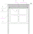
FIG. 1 is a plan view showing the arrangement of concrete supports and structural top plates.
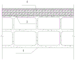
Fig. 2 is a cross-sectional view of a subterranean formation.
Fig. 3 is a longitudinal cross-sectional view of a subterranean structure.
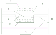
FIG. 4 is a schematic view showing the connection between a concrete support and a structural top plate.
In the figure, 1-fender pile, 2-pile top crown beam, 3-concrete support, 4-underground structure, 5-structure top plate, 6-backfill, 7-concrete support stress bar, 8-reinforcing bar, 9-reinforcing bar connector, 10-interfacial agent, 11-top plate reinforcing bar and 12-waist beam.
Detailed Description
The present invention will be described in detail with reference to specific embodiments.
The invention relates to a concrete support and structural top plate combined construction system based on permanent and temporary combination, provides a design idea of taking an existing deep foundation pit engineering inner support as a permanent structure, and enriches functions of a deep foundation pit supporting system.
The system comprises an underground structure 4, fender posts 1, wales 12 and concrete supports 3. The fender pile 1 is positioned at the outer side of the periphery of the underground structure 4, the pile top is positioned above the top plate of the underground structure 4 by a certain distance, and the pile bottom is positioned below the bottom plate of the underground structure 4 by a certain distance; the inner side of the fender post 1 is provided with a waist beam 12, the concrete support 3 is rigidly connected with the waist beams 12 at two sides and effectively transfers force, and the concrete support 3 is positioned at the top plate of the underground structure 4.
The top of the fender pile 1 is provided with a pile top crown beam 2, and the fender pile 1 is connected with the pile top crown beam 2 through embedded bars.
The waist beam 12 is positioned at the inner side of the fender post 1 and is connected through embedded bars or stress steel bars reserved in the fender post 1; the inner side of the waist rail 12 is reserved with a connector of a stressed steel bar or an embedded steel bar for connecting with the concrete support 3. Longitudinal concrete support stress ribs 7 are arranged in the concrete supports 3, and two ends of each concrete support 3 are connected with the connectors of the reserved stress reinforcing steel bars or the embedded reinforcing steel bars on the inner sides of the waist beams 12 through the concrete support stress ribs 7. The concrete supporting stress ribs 7 can be arranged in one row or multiple rows according to the stress requirement of the structure.
The concrete supports 3 are embedded in the top surface of the structural roof 5 of the underground structure 4. Be provided with horizontal strengthening rib 8 in the concrete support 3, the strengthening rib 8 both ends are provided with reinforcing bar connector 9, and the strengthening rib 8 in the concrete support 3 is connected with the roof reinforcing bar 11 that corresponds in the structure roof 5 through reinforcing bar connector 9. The distance between the bottom of the concrete support 3 and the structural bottom plate 5 is not less than 300mm, and the requirements of passing through and force transmission of the top plate steel bar 11 are met. The structure contact surface between the concrete support 3 and the structure top plate 5 is roughened in advance, and the interface agent 10 is coated for two to three times. The concrete supports 3 are constructed when the foundation pit is excavated to the corresponding elevation, and are considered and jointly loaded with the structural top plate 5 according to the superposed members at the later stage, and are used as a part of the permanent underground structure 4.
The upper surface of the structure top plate 5 is in a regular gear-type concave-convex structure, the concrete support 3 is positioned on the upper surface of the structure top plate 5 and is in concave-convex mechanical engagement connection with the structure top plate 5
The number of the concrete supports 3 needs to be comprehensively determined according to the requirements of the stress and the durability of the integral component and the requirements of the stability and the surrounding environment protection during the excavation of the foundation pit, and the longitudinal distance between the concrete supports 3 along the underground structure 4 is more than or equal to 6m under the general condition.
And waterproof materials are arranged outside the structure top plate 5, the structure bottom plate and the structure side wall of the underground structure 4, so that the full-wrapping waterproof effect is realized. The waterproof materials on the outer sides of the structure side wall and the bottom plate can be pre-paved and reversely adhered to waterproof rolls, and the waterproof materials on the outer sides of the structure top plate 5 can be waterproof coatings.
The backfill soil 6 is arranged above the structural top plate 5, and is compacted in a layering mode, the compactness needs to meet the ground traffic requirement, and the compactness is not less than 93% under the general condition.
The concrete related to the fender post 1, the concrete support 3, the underground structure 4, the pile top crown beam 2 and the waist beam 12 is common waterproof concrete, and the related steel bars can be made of Q235 steel.
As shown in fig. 1-4, the underground structure 4 is generally composed of a cast-in-place reinforced concrete structure including a structural top plate 5 and a concrete support 3, the size of the members of the structural top plate 5 and the concrete support 3, the vertical distance between the bottom of the concrete support 3 and the structural top plate 5, the number of reinforcing ribs 8 inside the concrete support 3 and the type of the reinforcing ribs can be comprehensively determined according to the stress requirements of member connection and permanent structure, the number and the distribution spacing of the concrete supports 3 along the longitudinal direction of the underground structure 4 need to be comprehensively determined according to the stability and the peripheral environmental protection requirements during excavation of a foundation pit except for the comprehensive consideration of the stress and the durability of the co-constructed members of the permanent structural top plate 5, and the longitudinal spacing of the concrete supports 3 is more than or equal to 6m under.
The concrete related to all the reinforced concrete members is common waterproof concrete, the reinforcing steel bars and the connectors are made of Q235 steel, and the interface agent between the concrete support and the structural top plate can be epoxy resin.
The temporary concrete support in the foundation pit is used as a part of the structural top plate, and the external load is jointly borne according to the permanent structure, so that the concrete support is prevented from being chiseled out as a temporary component, the process is simplified, the progress is accelerated, the investment is saved, the size of the structural top plate is reduced, the integral stress requirement of the structure is met, a new idea of comprehensively considering the temporary concrete support and the permanent structure is provided for the first time, and the original design of the 'permanent temporary combination' concrete support is realized. The design concept of 'the concrete support and structure top plate combined construction process based on permanent and temporary combination' is a great improvement on the design of the existing deep and large foundation pit inner support system, provides a brand new thought for practicing green, environment-friendly and safe underground engineering, is simple in construction process, clear in concept and simple and convenient to construct, and provides a brand new thought for realizing underground energy-saving engineering.
The combined construction process of permanently and temporarily combined concrete support and structural top plate includes the following steps:
the method comprises the following steps: arranging a dewatering well outside the outline of the foundation pit based on the outline of the underground structure 4, and carrying out dewatering construction in 1 month before excavation of the foundation pit;
step two: lofting is carried out according to the coordinates and construction errors of the fender pile 1, then the fender pile 1 is constructed, and the fender pile 1 construction is carried out according to the main sequence of drill positioning, hole forming, hole cleaning, steel reinforcement cage laying, concrete pouring, pile top laitance cleaning and the like;
step three: drawing a groove at the top of the fender post 1 for excavation, constructing a post top crown beam 2, and then performing foundation pit excavation construction according to the principle of supporting along with excavation;
step four: when the foundation pit is excavated to a position 0.5m below the concrete support 3, the concrete waist beam 12 is constructed in time, the concrete waist beam 12 is connected with the fender post 1 through embedded steel bars, and meanwhile, a stressed steel bar or embedded steel bar connector is reserved on the other side of the waist beam 12;
step five: according to the arrangement and the section size of the concrete supports 3, groove-drawing excavation is carried out on the soil body in the foundation pit, then leveling is carried out, a cushion layer is laid, a reinforcement framework of the concrete supports 3 is bound in situ, concrete support stress ribs 7 are arranged, reinforcing ribs 8 are arranged, the positions of the reinforcing ribs 8 correspond to the reinforcement 11 of the top plate, and reinforcing bar connectors 9 are reserved on two side faces of the concrete supports 3; the connection between the waist beam 12 and the concrete support 3 is carried out by reserving a stressed steel bar or a pre-embedded steel bar connector on the waist beam 12 in advance;
pouring the concrete support 3 according to the requirement, and maintaining according to the specified requirement;
step six: after the concrete supports 3 reach the specified curing age and the design strength, continuously excavating the foundation pit based on the principle of following excavation and supporting until the bottom of the foundation pit is reached, adopting manual excavation 0.5m above the bottom of the pit, then timely leveling the bottom of the pit, laying a waterproof layer and a plain concrete cushion layer, binding reinforcing steel bars, pouring a structural bottom plate, a structural side wall and a structural middle plate, and timely removing the inner supports at corresponding positions in the pouring process of the main body structure;
step seven: roughening the surface of a concrete support 3 at the contact part of a structural top plate 5 and the concrete support 3, then coating an interface agent 10 for 2-3 times, reserving reinforcing steel bar connectors 9 on two sides of the concrete support 3, mechanically connecting reinforcing steel bars 8 arranged in the middle of the concrete support 3 with reinforcing steel bars 11 of the top plate, and then pouring the structural top plate 5 as required;
the distance between the bottom of the concrete support 3 and the bottom surface of the structural bottom plate 5 is not less than 300 mm;
step eight: the soil is backfilled in layers above the structural top plate 5, and the compactness of the backfilled soil 6 is not less than 93%;
step nine: all structures within a range of 3m below the earth surface are chiseled, and laying paths are reserved for underground structures such as later-stage municipal pipelines.
The temporary inner support of the foundation pit which can adapt to any condition and can be used as an underground main structure is found out theoretically, and the temporary inner support of the foundation pit still has great difficulty under the existing theoretical level and construction technical conditions, because the engineering shapes of various foundation pits are different, the depth of the foundation pit is different from the erection position of the inner support, and meanwhile, the stress and the durability requirement of the main structure are not completely consistent. The concrete supports at the top plate of the structure are designed according to permanent stress components, so that the safety of the foundation pit, the stress reliability of the underground structure and the long-term stability are ensured to the greatest extent. The current ever-present combined concrete support and structure top plate combined construction process still needs the basic principles of first function, local adjustment, medicine administration according to the symptoms and flexible application.
The temporary concrete support in the foundation pit is used as a part of the structural top plate and bears external load together with the permanent structure, so that the temporary concrete support is prevented from being chiseled out as a temporary component, the process is simplified, the progress is accelerated, the size of the structural top plate is reduced, the integral stress requirement of the underground structure is met, a new idea of considering the temporary concrete support and the permanent top plate together is provided for the first time, the safety, green and environment-friendly design concept of underground engineering is improved, the economic benefit and the social benefit are higher, and the application prospect in the engineering of urban rail transit, railways, highways and the like is wide.
The invention is not limited to the examples, and any equivalent changes to the technical solution of the invention by a person skilled in the art after reading the description of the invention are covered by the claims of the invention.
Claims (10)
1. Concrete support and structure roof build system jointly based on face combination forever, its characterized in that:
the system comprises an underground structure (4), fender posts (1), wales (12) and concrete supports (3);
the fender post (1) is positioned at the outer side of the underground structure (4), the top of the post is higher than the top plate of the underground structure (4), and the bottom of the post is below the bottom plate of the underground structure (4);
a waist beam (12) is arranged on the inner side of the fender pile (1), a crown beam (2) is arranged on the pile top, a concrete support (3) is rigidly connected with the waist beam (12) and effectively transfers force, and the concrete support (3) is positioned at the top of the underground structure (4).
2. The permanent temporary combination-based concrete support and structural roof combined building system of claim 1, wherein:
underground structure (4) are including structure roof (5), structure medium plate, structure bottom plate, structure side wall and structure center pillar, and fender post (1) is located underground structure (4) outside all around, and waist rail (12) and concrete support (3) are located structure roof (5) top.
3. The permanent temporary combination-based concrete support and structural roof combined building system of claim 2, wherein:
the top of the fender pile (1) is provided with a pile top crown beam (2), and the fender pile (1) is effectively connected with the crown beam (2) through embedded bars or reserved bars.
4. The permanent temporary combination-based concrete support and structural roof combined building system of claim 3, wherein:
the waist beam (12) is positioned at the inner side of the fender post (1) and connected through embedded bars; the inner side of the waist rail (12) is reserved with a stressed steel bar or a pre-buried steel bar connector.
5. The permanent temporary combination-based concrete support and structural roof combined building system of claim 4, wherein:
the concrete support (3) is internally provided with a concrete support stress rib (7), and two ends of the concrete support (3) are connected with a reserved stress reinforcing steel bar or an embedded reinforcing steel bar connector on the inner side of the waist rail (12) through the concrete support stress rib (7).
6. The permanent temporary combination-based concrete support and structural roof combined building system of claim 5, wherein:
the upper surface of the structural top plate (5) is in a regular gear-type concave-convex structure, and the concrete support (3) is positioned on the upper surface of the structural top plate (5) and is in concave-convex mechanical engagement connection with the structural top plate (5);
a transverse reinforcing rib (8) is arranged in the concrete support (3), reinforcing steel bar connectors (9) are reserved at two ends of the reinforcing rib (8), and the reinforcing rib (8) in the concrete support (3) is connected with a corresponding reinforcing steel bar (11) in the structural top plate (5) through the reinforcing steel bar connectors (9).
7. The permanent temporary combination-based concrete support and structural roof combined building system of claim 6, wherein:
the contact surface between the concrete support (3) and the structural top plate (5) is subjected to roughening treatment and coated with an interfacial agent (10).
8. The permanent temporary combination-based concrete support and structural roof combined building system of claim 7, wherein:
and waterproof materials are arranged outside the structure top plate (5), the structure bottom plate and the structure side wall of the underground structure (4) to completely cover the underground structure.
9. The permanent temporary combination-based concrete support and structural roof combined building system of claim 8, wherein:
and backfill soil (6) is arranged above the structural top plate (5), and the backfill soil (6) is backfilled in layers.
10. A method for constructing a concrete support and structure top plate combined system based on permanent and temporary combination is characterized by comprising the following steps:
the method comprises the following steps:
the method comprises the following steps: arranging a precipitation well outside the outline of the foundation pit based on the outline of the underground structure (4), and performing precipitation construction within 1 month before excavation of the foundation pit;
step two: lofting is carried out according to the coordinates and construction errors of the fender pile (1), then the fender pile (1) is constructed, and the fender pile (1) construction is carried out according to the sequence of in-place of a drilling machine, hole forming, hole cleaning, steel reinforcement cage laying, concrete pouring and pile top laitance cleaning;
step three: drawing a groove at the top of the fender post (1) for excavation, constructing a pile top crown beam (2), and then performing foundation pit excavation construction according to the principle of excavation and supporting;
step four: when the foundation pit is excavated to a position 0.5m below the concrete support (3), a concrete waist beam (12) is constructed in time, the concrete waist beam (12) is connected with the fender post (1) through embedded steel bars, and meanwhile, a stressed steel bar or an embedded steel bar connector is reserved on the other side of the waist beam (12);
step five: according to the arrangement and the section size of the concrete supports (3), groove-drawing excavation is carried out on the soil body in the foundation pit, then leveling is carried out, a cushion layer is laid, a reinforcement framework of the concrete supports (3) is bound in situ, concrete support stress ribs (7) are arranged, reinforcing ribs (8) are arranged, the positions of the reinforcing ribs (8) correspond to the top plate reinforcing steel bars (11), and reinforcing steel bar connectors (9) are reserved on two side faces of the concrete supports (3); the waist beam (12) is connected with the concrete support (3) by pre-reserving a stressed steel bar or a pre-embedded steel bar connector on the waist beam (12);
pouring concrete supports (3) according to requirements, and curing according to the specified requirements;
step six: after the concrete supports (3) reach the specified curing age and the design strength, continuously excavating the foundation pit based on the principle of excavating along with the supports until the bottom of the foundation pit is reached, adopting manual excavation 0.5m above the pit bottom, then timely leveling the pit bottom, laying a waterproof layer and a plain concrete cushion layer, binding reinforcing steel bars, pouring a structural bottom plate, a structural side wall and a structural middle plate, and timely removing the inner supports at corresponding positions in the pouring process of the main body structure;
step seven: roughening the surface of a concrete support (3) at the contact part of a structural top plate (5) and the concrete support (3), then coating an interface agent (10) for 2-3 times, reserving reinforcing steel bar connectors (9) on the two sides of the concrete support (3), mechanically connecting reinforcing ribs (8) arranged in the middle of the concrete support (3) with reinforcing steel bars (11) of the top plate, and then pouring the structural top plate (5) according to requirements;
the distance between the bottom of the concrete support (3) and the bottom surface of the structural bottom plate (5) is not less than 300 mm;
step eight: the soil body is backfilled in a layering mode above the structural top plate (5), and the compactness of the backfilled soil (6) is not less than 93%;
step nine: all structures within a range of 3m below the earth surface are chiseled, and laying paths are reserved for underground structures such as later-stage municipal pipelines.
Priority Applications (1)
| Application Number | Priority Date | Filing Date | Title |
|---|---|---|---|
| CN202010250536.4A CN111305220A (en) | 2020-04-01 | 2020-04-01 | Concrete support and structural top plate combined building system based on permanent and temporary combination and construction method thereof |
Applications Claiming Priority (1)
| Application Number | Priority Date | Filing Date | Title |
|---|---|---|---|
| CN202010250536.4A CN111305220A (en) | 2020-04-01 | 2020-04-01 | Concrete support and structural top plate combined building system based on permanent and temporary combination and construction method thereof |
Publications (1)
| Publication Number | Publication Date |
|---|---|
| CN111305220A true CN111305220A (en) | 2020-06-19 |
Family
ID=71151820
Family Applications (1)
| Application Number | Title | Priority Date | Filing Date |
|---|---|---|---|
| CN202010250536.4A Pending CN111305220A (en) | 2020-04-01 | 2020-04-01 | Concrete support and structural top plate combined building system based on permanent and temporary combination and construction method thereof |
Country Status (1)
| Country | Link |
|---|---|
| CN (1) | CN111305220A (en) |
Cited By (2)
| Publication number | Priority date | Publication date | Assignee | Title |
|---|---|---|---|---|
| CN113266017A (en) * | 2021-06-15 | 2021-08-17 | 中铁四局集团第一工程有限公司 | Regulation and storage tank construction method based on 'permanent-face integrated' inner support structure of deep foundation pit |
| CN114457810A (en) * | 2022-01-26 | 2022-05-10 | 中铁第一勘察设计院集团有限公司 | Foundation pit inner support system based on permanent-temporary combination and construction method thereof |
-
2020
- 2020-04-01 CN CN202010250536.4A patent/CN111305220A/en active Pending
Cited By (3)
| Publication number | Priority date | Publication date | Assignee | Title |
|---|---|---|---|---|
| CN113266017A (en) * | 2021-06-15 | 2021-08-17 | 中铁四局集团第一工程有限公司 | Regulation and storage tank construction method based on 'permanent-face integrated' inner support structure of deep foundation pit |
| CN113266017B (en) * | 2021-06-15 | 2022-05-17 | 中铁四局集团第一工程有限公司 | Regulation and storage tank construction method based on 'permanent-face integrated' inner support structure of deep foundation pit |
| CN114457810A (en) * | 2022-01-26 | 2022-05-10 | 中铁第一勘察设计院集团有限公司 | Foundation pit inner support system based on permanent-temporary combination and construction method thereof |
Similar Documents
| Publication | Publication Date | Title |
|---|---|---|
| CN101914925B (en) | Basement by using optimized composite prefabricated arch wall as external wall | |
| CN108868778B (en) | Non-excavation construction method for large underground structure | |
| CN108252329B (en) | Assembly type comprehensive pipe gallery for bearing force of enclosure structure and construction method thereof | |
| CN108589771B (en) | Construction method for layer-adding transfer node of operated underground station | |
| CN102995659B (en) | Method for constructing from central area to periphery of ultra-large type underground engineering | |
| CN101418569B (en) | Optimization complex arch wall combining prefabricated arch leaf, support and major structure | |
| CN210598987U (en) | Subway station based on single-layer four-guide-hole and middle-guide-hole inner pile foundation | |
| CN108678751B (en) | Assembly type construction method of shield cutter head manhole by jacking and excavating firstly | |
| CN110777850A (en) | Existing pipe gallery underground space, supporting structure thereof and construction method of supporting structure | |
| CN111305220A (en) | Concrete support and structural top plate combined building system based on permanent and temporary combination and construction method thereof | |
| CN112922646B (en) | Building method of underground excavation station excavated by large-section single-span support through superposed arch-wall integrated type | |
| CN111809662B (en) | Subway station underground structure combination construction method | |
| CN212835532U (en) | Post-cast strip sealing structure capable of backfilling basement outer wall in advance | |
| CN103882883A (en) | Method for constructing foundation shared by tower crane and garage frame column | |
| CN212001126U (en) | Concrete support and structure top plate combined building system based on permanent-temporary combination | |
| CN115324104A (en) | Permanent and temporary combined assembly type station and construction method thereof | |
| CN115387378A (en) | Semi-pillarless assembly type station based on simply supported superposed side walls and floorslabs and method thereof | |
| CN211421179U (en) | Existing pipe gallery underground space and supporting construction thereof | |
| CN212642730U (en) | Collapsible loess area tunnel passes people's air defense structure | |
| CN112049117B (en) | Earth-rock binary foundation pit supporting structure system | |
| CN212052780U (en) | Oblique supporting type deep foundation pit supporting structure | |
| CN112664203A (en) | Reinforcing system for controlling deformation of shield tunnel by dredging river above shield tunnel and construction method | |
| CN216198134U (en) | Waterproof novel subway station is led to full row of half package | |
| CN219605277U (en) | Reverse construction structure of vertical shaft | |
| CN113073666B (en) | Island building process for high slope peninsula cable tower construction platform |
Legal Events
| Date | Code | Title | Description |
|---|---|---|---|
| PB01 | Publication | ||
| PB01 | Publication | ||
| SE01 | Entry into force of request for substantive examination | ||
| SE01 | Entry into force of request for substantive examination |