CN111266331A - Intelligent automatic plate cleaning machine - Google Patents
Intelligent automatic plate cleaning machine Download PDFInfo
- Publication number
- CN111266331A CN111266331A CN202010170977.3A CN202010170977A CN111266331A CN 111266331 A CN111266331 A CN 111266331A CN 202010170977 A CN202010170977 A CN 202010170977A CN 111266331 A CN111266331 A CN 111266331A
- Authority
- CN
- China
- Prior art keywords
- frame
- fixed outer
- outer frame
- conveying
- pipe
- Prior art date
- Legal status (The legal status is an assumption and is not a legal conclusion. Google has not performed a legal analysis and makes no representation as to the accuracy of the status listed.)
- Withdrawn
Links
- 238000004140 cleaning Methods 0.000 title claims abstract description 33
- 238000005096 rolling process Methods 0.000 claims abstract description 31
- XLYOFNOQVPJJNP-UHFFFAOYSA-N water Substances O XLYOFNOQVPJJNP-UHFFFAOYSA-N 0.000 claims abstract description 27
- OKTJSMMVPCPJKN-UHFFFAOYSA-N Carbon Chemical compound [C] OKTJSMMVPCPJKN-UHFFFAOYSA-N 0.000 claims abstract description 18
- 230000001681 protective effect Effects 0.000 claims abstract description 15
- 238000001035 drying Methods 0.000 claims abstract description 14
- 239000002699 waste material Substances 0.000 claims abstract description 14
- 238000001914 filtration Methods 0.000 claims abstract description 12
- 238000007599 discharging Methods 0.000 claims abstract description 11
- 239000007921 spray Substances 0.000 claims abstract description 11
- 238000009423 ventilation Methods 0.000 claims description 27
- 238000010438 heat treatment Methods 0.000 claims description 12
- RYGMFSIKBFXOCR-UHFFFAOYSA-N Copper Chemical compound [Cu] RYGMFSIKBFXOCR-UHFFFAOYSA-N 0.000 claims description 11
- 229910052802 copper Inorganic materials 0.000 claims description 11
- 239000010949 copper Substances 0.000 claims description 11
- 229910001220 stainless steel Inorganic materials 0.000 claims description 7
- 239000010935 stainless steel Substances 0.000 claims description 7
- 239000007788 liquid Substances 0.000 abstract description 7
- 239000000853 adhesive Substances 0.000 abstract 1
- 230000001070 adhesive effect Effects 0.000 abstract 1
- 239000003381 stabilizer Substances 0.000 description 5
- 239000000428 dust Substances 0.000 description 3
- 230000005540 biological transmission Effects 0.000 description 2
- 238000001514 detection method Methods 0.000 description 2
- 230000000694 effects Effects 0.000 description 2
- 230000009286 beneficial effect Effects 0.000 description 1
- 238000007664 blowing Methods 0.000 description 1
- 238000010586 diagram Methods 0.000 description 1
- 238000009429 electrical wiring Methods 0.000 description 1
- 239000012535 impurity Substances 0.000 description 1
- 239000002184 metal Substances 0.000 description 1
- 229910052751 metal Inorganic materials 0.000 description 1
- 238000000034 method Methods 0.000 description 1
- 238000002360 preparation method Methods 0.000 description 1
- 238000003860 storage Methods 0.000 description 1
Images

Classifications
-
- B—PERFORMING OPERATIONS; TRANSPORTING
- B08—CLEANING
- B08B—CLEANING IN GENERAL; PREVENTION OF FOULING IN GENERAL
- B08B1/00—Cleaning by methods involving the use of tools
- B08B1/10—Cleaning by methods involving the use of tools characterised by the type of cleaning tool
- B08B1/12—Brushes
-
- B—PERFORMING OPERATIONS; TRANSPORTING
- B01—PHYSICAL OR CHEMICAL PROCESSES OR APPARATUS IN GENERAL
- B01D—SEPARATION
- B01D29/00—Filters with filtering elements stationary during filtration, e.g. pressure or suction filters, not covered by groups B01D24/00 - B01D27/00; Filtering elements therefor
- B01D29/01—Filters with filtering elements stationary during filtration, e.g. pressure or suction filters, not covered by groups B01D24/00 - B01D27/00; Filtering elements therefor with flat filtering elements
- B01D29/03—Filters with filtering elements stationary during filtration, e.g. pressure or suction filters, not covered by groups B01D24/00 - B01D27/00; Filtering elements therefor with flat filtering elements self-supporting
-
- B—PERFORMING OPERATIONS; TRANSPORTING
- B01—PHYSICAL OR CHEMICAL PROCESSES OR APPARATUS IN GENERAL
- B01D—SEPARATION
- B01D35/00—Filtering devices having features not specifically covered by groups B01D24/00 - B01D33/00, or for applications not specifically covered by groups B01D24/00 - B01D33/00; Auxiliary devices for filtration; Filter housing constructions
- B01D35/02—Filters adapted for location in special places, e.g. pipe-lines, pumps, stop-cocks
-
- B—PERFORMING OPERATIONS; TRANSPORTING
- B08—CLEANING
- B08B—CLEANING IN GENERAL; PREVENTION OF FOULING IN GENERAL
- B08B1/00—Cleaning by methods involving the use of tools
- B08B1/20—Cleaning of moving articles, e.g. of moving webs or of objects on a conveyor
-
- B—PERFORMING OPERATIONS; TRANSPORTING
- B08—CLEANING
- B08B—CLEANING IN GENERAL; PREVENTION OF FOULING IN GENERAL
- B08B13/00—Accessories or details of general applicability for machines or apparatus for cleaning
-
- B—PERFORMING OPERATIONS; TRANSPORTING
- B08—CLEANING
- B08B—CLEANING IN GENERAL; PREVENTION OF FOULING IN GENERAL
- B08B3/00—Cleaning by methods involving the use or presence of liquid or steam
- B08B3/02—Cleaning by the force of jets or sprays
- B08B3/022—Cleaning travelling work
-
- F—MECHANICAL ENGINEERING; LIGHTING; HEATING; WEAPONS; BLASTING
- F26—DRYING
- F26B—DRYING SOLID MATERIALS OR OBJECTS BY REMOVING LIQUID THEREFROM
- F26B21/00—Arrangements or duct systems, e.g. in combination with pallet boxes, for supplying and controlling air or gases for drying solid materials or objects
- F26B21/001—Drying-air generating units, e.g. movable, independent of drying enclosure
-
- F—MECHANICAL ENGINEERING; LIGHTING; HEATING; WEAPONS; BLASTING
- F26—DRYING
- F26B—DRYING SOLID MATERIALS OR OBJECTS BY REMOVING LIQUID THEREFROM
- F26B21/00—Arrangements or duct systems, e.g. in combination with pallet boxes, for supplying and controlling air or gases for drying solid materials or objects
- F26B21/004—Nozzle assemblies; Air knives; Air distributors; Blow boxes
Landscapes
- Engineering & Computer Science (AREA)
- Chemical & Material Sciences (AREA)
- Chemical Kinetics & Catalysis (AREA)
- Mechanical Engineering (AREA)
- General Engineering & Computer Science (AREA)
- Cleaning In General (AREA)
Abstract
The invention provides an intelligent automatic plate cleaning machine which comprises a fixed outer frame, longitudinal support legs, a left conveying roller, a left conveying belt, a left driven wheel, a leading-in frame, a transverse water conveying pipe, a solenoid valve, a spray head, a sensor, a waste filtering and discharging frame structure, a cleaning frame structure, a supporting conveying frame structure, a drying frame structure, a protective cover, a controller, a driving motor, a driving wheel and a driving belt, wherein the number of the longitudinal support legs is four, and the longitudinal support legs are arranged at four corners of the lower part of the fixed outer frame through bolts; the left conveying roller is provided with two conveying rollers. The lower side rolling brush and the upper side rolling brush are respectively arranged on the inner sides of the side edge connecting plates, so that the plates passing through the inner sides of the lower side rolling brush and the upper side rolling brush can be conveniently cleaned when the plate cleaning machine is used; the activated carbon filter screen is connected to the lower part of the inner side of the threaded pipe in an adhesive manner, so that the liquid guided out of the threaded pipe through the guide pipe can be conveniently filtered.
Description
Technical Field
The invention belongs to the technical field of plate cleaning, and particularly relates to an intelligent automatic plate cleaning machine.
Background
Before the detection of the PCB, a worker usually needs to clean the PCB to prevent impurities such as dust on the PCB from affecting the detection result of the PCB.
But the clear machine of current board still has the dust clearance inconvenient on to the face, and is inconvenient to filter the waste liquid of discharge, and the inconvenient board that finishes to the cleanness is dried and the inconvenient problem that props up panel.
Therefore, the intelligent automatic plate cleaning machine is very necessary to be invented.
Disclosure of Invention
In order to solve the technical problems, the invention provides an intelligent automatic plate cleaning machine to solve the problems that the existing plate cleaning machine is inconvenient to clean dust on a plate surface, filter discharged waste liquid, dry a cleaned plate and support the plate. The intelligent automatic plate cleaning machine comprises a fixed outer frame, four longitudinal support legs, a left conveying roller, a left conveying belt, a left driven wheel, a guide-in frame, a transverse water conveying pipe, a solenoid valve, a spray head, a sensor, a waste filtering and discharging frame structure, a cleaning frame structure, a supporting conveying frame structure, a drying frame structure, a protective cover, a controller, a driving motor, a driving wheel and a driving belt, wherein the number of the longitudinal support legs is four, and the longitudinal support legs are arranged at four corners of the lower part of the fixed outer frame through bolts; the left conveying rollers are arranged in two, and the left conveying rollers are connected to the left side of the middle position of the fixed outer frame and the middle position of the fixed outer frame in a rolling mode; the left conveying belt is sleeved on the outer side of the left conveying roller; the left driven wheel is arranged in the middle of the front side in the fixed outer frame, and is connected to the front side of the left conveying roller through a key; the horizontal water pipe screw is arranged at the upper part of the left side of the fixed outer frame; the electromagnetic valve is in threaded connection with the left side of the transverse water conveying pipe; the plurality of spray heads are arranged and are respectively in threaded connection with the lower part of the transverse water conveying pipe; the sensor is glued on the left side of the lower part of the transverse water conveying pipe; the waste filtering and discharging frame structure is arranged at the left lower side inside the fixed outer frame; the cleaning frame structure is arranged at the middle lower part in the fixed outer frame; the supporting and conveying frame structure is arranged at the right lower side inside the fixed outer frame; the drying rack structure is arranged at the right upper side inside the fixed outer frame; the protective cover bolt is arranged at the middle upper part of the fixed outer frame; the controller screw is arranged at the top of the protective cover; the driving wheel is connected to the front output shaft of the driving motor in a key manner; the cleaning frame structure comprises a bottom mounting seat, a side connecting plate, a lower side fixing rod, a lower side rolling brush, an upper side fixing rod and an upper side rolling brush, wherein the bottom mounting seat is mounted at the middle lower part inside the fixed outer frame through bolts; the number of the side connecting plates is two, and the front side and the rear side of the upper part of each side connecting plate are two; the lower side fixing rod is inserted at the lower part of the inner side of the side edge connecting plate; the lower side rolling brush is axially connected to the outer side of the lower side fixing rod; the upper side fixing rod is inserted at the upper part of the side edge connecting plate; the upper side rolling brush is axially connected to the outer side of the upper side fixing rod.
Preferably, the supporting and conveying frame structure comprises a right conveying roller, a right conveying belt, a right driven wheel, a rubber supporting leg and a ventilation opening, wherein the right conveying roller is provided with two sides and is respectively connected to the right side of the middle position of the fixed outer frame and the middle position of the fixed outer frame in a shaft manner; the right conveying belt is sleeved outside the right conveying roller; the right side driven wheel is arranged in the middle of the front side of the inner part of the fixed outer frame, and is connected to the front side of the right side conveying roller through a key.
Preferably, the drying rack structure comprises two ventilation frames, a transverse rod, a blower, a red copper heating pipe and a stainless steel protecting net, wherein the ventilation frames are respectively installed on the right upper side inside the fixed outer frame through screws; the transverse rod screw is arranged on the top of the inner wall of the ventilation frame; the red copper heating pipe is mounted at the lower part of the inner side of the ventilation frame through screws.
Preferably, the waste filtering and discharging frame structure comprises a guiding hopper, a guiding pipe, a threaded pipe, a limiting block and an activated carbon filter screen, wherein the guiding pipe is inserted at the left side of the lower part of the guiding hopper; the threaded pipe is in threaded connection with the lower part of the outer side of the delivery pipe; the limiting block is glued on the upper part of the inner side of the threaded pipe.
Preferably, the lower side rolling brush and the upper side rolling brush are respectively arranged on the inner sides of the side connecting plates.
Preferably, the activated carbon filter screen is glued on the lower part of the inner side of the threaded pipe.
Preferably, the blower is disposed inside the ventilating frame while the bolt is installed at the lower portion of the cross bar.
Preferably, the rubber stabilizer blade be provided with a plurality ofly, the outside of right side conveyer belt respectively of rubber stabilizer blade.
Preferably, the stainless steel protecting net screw is arranged on the lower side of the ventilation frame.
Preferably, the driving motor is installed at the bottom of the inner wall of the protective cover through a bolt.
Preferably, the ventilation openings are arranged in a plurality of numbers, and the ventilation openings are arranged on the inner sides of the rubber support legs and are simultaneously arranged on the right conveyor belt.
Preferably, the lead-in frame is installed at the left side of the inside of the fixed outer frame through a bolt, and the lead-in frame inclines downwards from left to right.
Preferably, the guiding-out hopper is arranged at the lower part of the left side conveying belt, and the screw is arranged at the bottom of the fixed outer frame.
Preferably, the transmission belt is sleeved on the outer sides of the driving wheel, the left driven wheel and the right driven wheel.
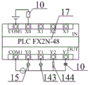
Preferably, the controller adopts FX2N-48 series PLC, the sensor adopts a metal sensor with the model I2B0802NO, the blower adopts an SF axial flow fan, the electromagnetic valve adopts a two-watt normally closed electromagnetic valve, the driving motor adopts a Y2-1 motor, the sensor is electrically connected with the input end of the controller, and the driving motor, the electromagnetic valve, the blower and the red copper heating pipe are electrically connected with the output end of the controller.
Compared with the prior art, the invention has the beneficial effects that:
1. in the invention, the lower side rolling brush and the upper side rolling brush are respectively arranged on the inner sides of the side edge connecting plates, so that the plates passing through the inner sides of the lower side rolling brush and the upper side rolling brush can be conveniently cleaned when in use.
2. In the invention, the activated carbon filter screen is glued at the lower part of the inner side of the threaded pipe, so that the liquid led out of the threaded pipe through the leading-out pipe can be conveniently filtered when the filter screen is used.
3. In the invention, the blower is arranged on the inner side of the ventilation frame, and the bolt is arranged on the lower part of the transverse rod, so that hot air heated by the red copper heating pipe can be conveniently blown to a plate passing through the right conveying belt for drying.
4. According to the invention, the plurality of rubber support legs are arranged, and the rubber support legs are respectively arranged at the outer sides of the right side conveying belts, so that the cleaned plate trough plate can be conveniently supported when the plate trough plate is used.
5. According to the invention, the stainless steel protecting net screw is arranged on the lower side of the ventilation frame, so that the upward tilting of the plate can be avoided when the ventilation frame is used, and the lower part of the ventilation frame can be protected.
6. According to the invention, the driving motor bolt is arranged at the bottom of the inner wall of the protective cover, so that the driving motor can be conveniently protected when in use, and the influence of water splashing on the driving motor is avoided.
7. According to the invention, the ventilation opening is arranged on the inner side of the rubber support leg and is arranged on the right conveyor belt, so that the ventilation effect on the right conveyor belt can be increased when the drying device is used, and plates can be dried better.
8. According to the invention, the lead-in frame bolt is arranged on the left side in the fixed outer frame, and the lead-in frame inclines downwards from left to right, so that the plate can be conveyed to the left side conveyor belt when in use.
9. In the invention, the guiding-out hopper is arranged at the lower part of the left conveying belt, and the screw is arranged at the bottom of the fixed outer frame, so that the dropping water liquid can be conveniently collected when the device is used.
10. According to the plate conveying device, the driving belt is sleeved on the outer sides of the driving wheel, the left driven wheel and the right driven wheel, so that the driving motor can drive the left conveying roller to rotate through the driving wheel and the driving belt, and the right driven wheel can drive the right conveying roller to rotate, so that the left conveying belt and the right conveying belt can be driven to rotate, and plates can be conveniently conveyed.
Drawings
Fig. 1 is a schematic structural view of the present invention.
Fig. 2 is a schematic structural view of a waste filtering discharge frame structure of the present invention.
Fig. 3 is a schematic structural view of the structure of the cleaning frame of the present invention.
Fig. 4 is a schematic structural view of the inventive jack-up carriage structure.
Fig. 5 is a schematic structural view of a drying rack structure of the present invention.
Fig. 6 is a schematic electrical wiring diagram of the present invention.
In the figure:
1. fixing the outer frame; 2. a longitudinal leg; 3. a left conveying roller; 4. a left side conveyor belt; 5. a left driven wheel; 6. importing a frame; 7. a transverse water conveying pipe; 8. an electromagnetic valve; 9. a spray head; 10. a sensor; 11. a waste filtering and discharging frame structure; 111. a leading-out hopper; 112. a delivery pipe; 113. a threaded pipe; 114. a limiting block; 115. an activated carbon filter screen; 12. a cleaning frame structure; 121. a bottom mounting base; 122. side edge connecting plates; 123. a lower side fixing rod; 124. a lower side rolling brush; 125. an upper side fixing rod; 126. an upper side rolling brush; 13. supporting the conveying frame structure; 131. a right conveying roller; 132. a right side conveyor belt; 133. a right driven wheel; 134. a rubber foot; 135. a vent; 14. a drying rack structure; 141. a ventilation frame; 142. a transverse bar; 143. a blower; 144. a red copper heating pipe; 145. a stainless steel protective net; 15. a protective cover; 16. a controller; 17. a drive motor; 18. a driving wheel; 19. a transmission belt.
Detailed Description
The invention is further described below with reference to the accompanying drawings:
example (b):
as shown in figures 1 and 3
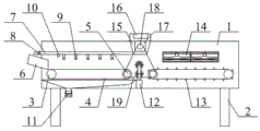
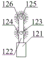
The invention provides an intelligent automatic plate cleaning machine which comprises a fixed outer frame 1, longitudinal support legs 2, a left conveying roller 3, a left conveying belt 4, a left driven wheel 5, a lead-in frame 6, a transverse water conveying pipe 7, an electromagnetic valve 8, a spray head 9, a sensor 10, a waste filtering and discharging frame structure 11, a cleaning frame structure 12, a supporting conveying frame structure 13, a drying frame structure 14, a protective cover 15, a controller 16, a driving motor 17, a driving wheel 18 and a driving belt 19, wherein the number of the longitudinal support legs 2 is four, and the longitudinal support legs 2 are arranged at four corners of the lower part of the fixed outer frame 1 through bolts; the number of the left conveying rollers 3 is two, and the left conveying rollers 3 are connected to the left side and the middle position of the fixed outer frame 1 in a shaft mode; the left conveying belt 4 is sleeved on the outer side of the left conveying roller 3; the left driven wheel 5 is arranged in the middle of the front side in the fixed outer frame 1 and is connected to the front side of the left conveying roller 3 in a key mode; the horizontal water pipe 7 is arranged at the upper part of the left side of the fixed outer frame 1 through a screw; the electromagnetic valve 8 is in threaded connection with the left side of the transverse water conveying pipe 7; a plurality of spray heads 9 are arranged, and the spray heads 9 are respectively in threaded connection with the lower parts of the transverse water conveying pipes 7; the sensor 10 is glued to the left side of the lower part of the transverse water conveying pipe 7; the waste filtering and discharging frame structure 11 is arranged at the left lower side inside the fixed outer frame 1; the cleaning frame structure 12 is arranged at the middle lower part of the inside of the fixed outer frame 1; the supporting and conveying frame structure 13 is arranged at the right lower side inside the fixed outer frame 1; the drying rack structure 14 is arranged at the right upper side inside the fixed outer frame 1; the protective cover 15 is mounted on the middle upper part of the fixed outer frame 1 through bolts; the controller 16 is mounted on the top of the protective cover 15 through screws; the driving wheel 18 is connected with the front output shaft of the driving motor 17 in a key way; the driving motor 17 is mounted at the bottom of the inner wall of the protective cover 15 through bolts, so that the driving motor 17 is conveniently protected when in use, thereby preventing water from splashing on the driving motor 17 and affecting the driving motor 17, the leading-in frame 6 is mounted at the left side inside the fixed outer frame 1 through bolts, the leading-in frame 6 is inclined from left to right, when in use, plates are conveyed onto the left conveying belt 4, the leading-out hopper 111 is arranged at the lower part of the left conveying belt 4, meanwhile, the screws are mounted at the bottom of the fixed outer frame 1, so that when in use, dropped water is conveniently collected, the driving belt 19 is sleeved at the outer sides of the driving wheel 18, the left driven wheel 5 and the right driven wheel 133, when in use, the driving motor 17 is conveniently used, the driving wheel 18 drives the left conveying roller 3 to rotate through the left driven wheel 5, and the right driven wheel 133 drives the right conveying roller 131, so as to drive the left side conveying belt 4 and the right side conveying belt 132 to rotate, thereby facilitating the transportation of the plate; the cleaning frame structure 12 comprises a bottom mounting seat 121, a side connecting plate 122, a lower fixing rod 123, a lower rolling brush 124, an upper fixing rod 125 and an upper rolling brush 126, wherein the bottom mounting seat 121 is mounted at the middle lower part of the inside of the fixing outer frame 1 through bolts; two side connecting plates 122 are arranged, and the front side and the rear side of the upper part of each side connecting plate 122 are provided; the lower fixing rod 123 is inserted into the lower part of the inner side of the side connecting plate 122; the lower rolling brush 124 is coupled to the outer side of the lower fixing rod 123; the upper fixing rod 125 is inserted into the upper part of the side connecting plate 122; the upper rolling brush 126 is coupled to the outer side of the upper fixing rod 125; the lower roller brush 124 and the upper roller brush 126 are respectively disposed inside the side connection plate 122, so that the plate passing through the lower roller brush 124 and the upper roller brush 126 is conveniently cleaned when in use.
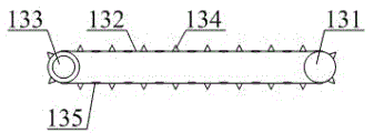
As shown in fig. 4, in the above embodiment, specifically, the supporting and conveying frame structure 13 includes a right conveying roller 131, a right conveying belt 132, a right driven wheel 133, a rubber foot 134 and a ventilation opening 135, the right conveying roller 131 is provided with two sides, and the right conveying roller 131 is respectively connected to the right side of the middle position of the fixed outer frame 1 and the middle position; the right conveying belt 132 is sleeved outside the right conveying roller 131; the right driven wheel 133 is arranged in the middle of the front side in the fixed outer frame 1 and is also connected with the front side of the right conveying roller 131 in a key mode; rubber stabilizer blade 134 be provided with a plurality ofly, rubber stabilizer blade 134 the outside of right side conveyer belt 132 respectively, the board groove panel that conveniently finishes to wasing props up when using, vent 135 set up in the inboard of rubber stabilizer blade 134, set up simultaneously on right side conveyer belt 132, can increase the ventilation effect to right side conveyer belt 132 when using to better dry to panel.
As shown in fig. 5, in the above embodiment, specifically, the drying rack structure 14 includes two ventilation frames 141, two transverse rods 142, a blower 143, a red copper heating pipe 144 and a stainless steel protecting net 145, and the ventilation frames 141 are respectively mounted on the right upper side of the inside of the fixing outer frame 1 by screws; the transverse rod 142 is mounted on the top of the inner wall of the ventilation frame 141 through screws; the red copper heating pipe 144 is mounted at the lower part of the inner side of the ventilation frame 141 by screws; air blower 143 set up the inboard at ventilation frame 141, the bolt is installed in the lower part of horizontal pole 142 simultaneously, and the steam after the convenient red copper heating pipe 144 heating blows to the panel through right side conveyer belt 132 and dries when using, stainless steel protecting wire 145 screw install the downside at ventilation frame 141, can avoid the panel perk that makes progress when using to can play safeguard function to ventilation frame 141's lower part.
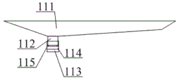
As shown in fig. 2, in the above embodiment, specifically, the waste filtering and discharging frame structure 11 includes an outlet hopper 111, an outlet pipe 112, a threaded pipe 113, a limiting block 114 and an activated carbon filter screen 115, where the outlet pipe 112 is inserted into the left side of the lower portion of the outlet hopper 111; the threaded pipe 113 is screwed on the lower part of the outer side of the delivery pipe 112; the limiting block 114 is glued on the upper part of the inner side of the threaded pipe 113; the activated carbon filter screen 115 is glued to the lower part of the inner side of the threaded pipe 113, and when in use, the liquid led out from the threaded pipe 113 through the leading-out pipe 112 is convenient to filter.
Principle of operation
In the working process of the invention, when in use, the PCB to be cleaned is sequentially placed in the lead-in frame 6, the controller 16 is used for controlling the driving motor 17 to work, the driving motor 17 drives the left conveying roller 3 to rotate through the driving wheel 18 and the left driven wheel 5 respectively by using the driving belt 19, the right conveying roller 131 is driven to rotate through the right driven wheel 133 so as to drive the left conveying belt 4 and the right conveying belt 132 to rotate, thereby conveying the PCB led in the lead-in frame 6 to the right side, when the sensor 10 detects the PCB, a signal is sent to the controller 16 to open the electromagnetic valve 8, water liquid is sprayed to the conveyed PCB from an external water source through the transverse water pipe 7 in the spray head 9, when the PCB passes through the lower rolling brush 124 and the upper rolling brush 126, the residues on the PCB are scraped by using the bristles on the outer sides of the lower rolling brush 124 and the upper rolling brush 126 and then guided to the right conveying belt 132, the rubber support legs 134 are used for supporting the PCB, and meanwhile, the blower 143 is used for blowing out the air heated by the red copper heating pipe 144 downwards, so that the cleaned PCB is convenient to dry, and finally the PCB is guided out of the right side of the fixed outer frame 1 to a storage box for preparation; and the water sprayed on the left side conveyor belt 4 is collected through the guiding hopper 111, then is guided into the guiding pipe 112, and finally is guided to the prepared water tank from the threaded pipe 113 to the lower side so as to be recycled, and meanwhile, the discharged water is filtered by the activated carbon filter screen 115.
The technical solutions of the present invention or similar technical solutions designed by those skilled in the art based on the teachings of the technical solutions of the present invention are all within the scope of the present invention.
Claims (10)
1. The intelligent automatic plate cleaning machine is characterized by comprising a fixed outer frame (1), four longitudinal support legs (2), a left conveying roller (3), a left conveying belt (4), a left driven wheel (5), a leading-in frame (6), a transverse water conveying pipe (7), an electromagnetic valve (8), a spray head (9), a sensor (10), a waste filtering and discharging frame structure (11), a cleaning frame structure (12), a supporting conveying frame structure (13), a drying frame structure (14), a protective cover (15), a controller (16), a driving motor (17), a driving wheel (18) and a driving belt (19), wherein the number of the longitudinal support legs (2) is four, and the longitudinal support legs (2) are arranged at four corners of the lower part of the fixed outer frame (1) through bolts; the number of the left conveying rollers (3) is two, and the left conveying rollers (3) are connected to the left side and the middle position of the fixed outer frame (1) in a shaft mode; the left conveying belt (4) is sleeved outside the left conveying roller (3); the left driven wheel (5) is arranged in the middle of the front side in the fixed outer frame (1) and is connected to the front side of the left conveying roller (3) in a key mode; the horizontal water pipe (7) is arranged at the upper part of the left side of the fixed outer frame (1) through a screw; the electromagnetic valve (8) is in threaded connection with the left side of the transverse water conveying pipe (7); a plurality of spray heads (9) are arranged, and the spray heads (9) are respectively in threaded connection with the lower part of the transverse water conveying pipe (7); the sensor (10) is glued to the left side of the lower part of the transverse water conveying pipe (7); the waste filtering and discharging frame structure (11) is arranged at the left lower side inside the fixed outer frame (1); the cleaning frame structure (12) is arranged at the middle lower part in the fixed outer frame (1); the supporting and conveying frame structure (13) is arranged at the right lower side inside the fixed outer frame (1); the drying rack structure (14) is arranged at the right upper side inside the fixed outer frame (1); the protective cover (15) is arranged on the middle upper part of the fixed outer frame (1) through bolts; the controller (16) is mounted at the top of the protective cover (15) through screws; the driving wheel (18) is connected to the front output shaft of the driving motor (17) in a key way; the cleaning frame structure (12) comprises a bottom mounting seat (121), a side connecting plate (122), a lower fixing rod (123), a lower rolling brush (124), an upper fixing rod (125) and an upper rolling brush (126), wherein the bottom mounting seat (121) is mounted at the middle lower part in the fixed outer frame (1) through bolts; the number of the side connecting plates (122) is two, and the front side and the rear side of the upper part of each side connecting plate (122) are arranged; the lower side fixing rod (123) is inserted into the lower part of the inner side of the side edge connecting plate (122); the lower side rolling brush (124) is axially connected to the outer side of the lower side fixing rod (123); the upper side fixing rod (125) is inserted at the upper part of the side connecting plate (122); the upper side rolling brush (126) is coupled to the outer side of the upper side fixing rod (125).
2. The intelligent automatic plate cleaning machine according to claim 1, wherein the supporting and conveying frame structure (13) comprises a right conveying roller (131), a right conveying belt (132), a right driven wheel (133), a rubber foot (134) and a ventilation opening (135), the right conveying roller (131) is provided with two sides, and the right conveying roller (131) is respectively connected to the right side and the middle position of the fixed outer frame (1) in a shaft manner; the right conveying belt (132) is sleeved outside the right conveying roller (131); the right driven wheel (133) is arranged in the middle of the front side in the fixed outer frame (1) and is connected to the front side of the right conveying roller (131) in a key mode.
3. The intelligent automatic plate cleaning machine according to claim 1, wherein the drying rack structure (14) comprises two ventilating frames (141), a transverse rod (142), a blower (143), a red copper heating pipe (144) and a stainless steel protecting net (145), and the ventilating frames (141) are respectively installed at the right upper side of the inside of the fixed outer frame (1) through screws; the transverse rod (142) is mounted on the top of the inner wall of the ventilation frame (141) through screws; the red copper heating pipe (144) is installed at the lower part of the inner side of the ventilation frame (141) through screws.
4. The intelligent automatic plate cleaning machine according to claim 1, wherein the waste filtering and discharging frame structure (11) comprises a discharge hopper (111), a discharge pipe (112), a threaded pipe (113), a limiting block (114) and an activated carbon filter screen (115), wherein the discharge pipe (112) is inserted into the left side of the lower part of the discharge hopper (111); the threaded pipe (113) is in threaded connection with the lower part of the outer side of the delivery pipe (112); the limiting block (114) is glued on the upper part of the inner side of the threaded pipe (113).
5. The intelligent automatic plate cleaning machine according to claim 1, wherein the lower side rolling brush (124) and the upper side rolling brush (126) are respectively arranged on the inner sides of the side connecting plates (122).
6. The intelligent automatic plate cleaning machine according to claim 3, wherein the blower (143) is disposed inside the ventilating frame (141) while being bolt-mounted on the lower portion of the cross bar (142).
7. The intelligent automatic plate cleaning machine according to claim 2, wherein a plurality of rubber feet (134) are provided, and the rubber feet (134) are respectively arranged at the outer sides of the right side conveyor belts (132).
8. The intelligent automatic plate cleaning machine according to claim 2, wherein a plurality of air vents (135) are provided, and the air vents (135) are provided on the inner side of the rubber support leg (134) and on the right side conveyor belt (132).
9. The intelligent automatic plate cleaning machine according to claim 1, wherein the lead-in frame (6) is mounted on the left side of the inside of the fixed outer frame (1) through bolts, and the lead-in frame (6) is inclined from left to right.
10. The intelligent automatic plate cleaning machine according to claim 2, wherein the driving belt (19) is sleeved outside the driving wheel (18), the left driven wheel (5) and the right driven wheel (133).
Priority Applications (1)
| Application Number | Priority Date | Filing Date | Title |
|---|---|---|---|
| CN202010170977.3A CN111266331A (en) | 2020-03-12 | 2020-03-12 | Intelligent automatic plate cleaning machine |
Applications Claiming Priority (1)
| Application Number | Priority Date | Filing Date | Title |
|---|---|---|---|
| CN202010170977.3A CN111266331A (en) | 2020-03-12 | 2020-03-12 | Intelligent automatic plate cleaning machine |
Publications (1)
| Publication Number | Publication Date |
|---|---|
| CN111266331A true CN111266331A (en) | 2020-06-12 |
Family
ID=70991459
Family Applications (1)
| Application Number | Title | Priority Date | Filing Date |
|---|---|---|---|
| CN202010170977.3A Withdrawn CN111266331A (en) | 2020-03-12 | 2020-03-12 | Intelligent automatic plate cleaning machine |
Country Status (1)
| Country | Link |
|---|---|
| CN (1) | CN111266331A (en) |
Cited By (2)
| Publication number | Priority date | Publication date | Assignee | Title |
|---|---|---|---|---|
| CN113399342A (en) * | 2021-05-17 | 2021-09-17 | 吉林中维科环境科技有限公司 | Environment-friendly material production edulcoration equipment |
| CN114146969A (en) * | 2021-12-15 | 2022-03-08 | 西安电子科技大学 | Cleaning and maintaining equipment for multifunctional integrated circuit |
-
2020
- 2020-03-12 CN CN202010170977.3A patent/CN111266331A/en not_active Withdrawn
Cited By (2)
| Publication number | Priority date | Publication date | Assignee | Title |
|---|---|---|---|---|
| CN113399342A (en) * | 2021-05-17 | 2021-09-17 | 吉林中维科环境科技有限公司 | Environment-friendly material production edulcoration equipment |
| CN114146969A (en) * | 2021-12-15 | 2022-03-08 | 西安电子科技大学 | Cleaning and maintaining equipment for multifunctional integrated circuit |
Similar Documents
| Publication | Publication Date | Title |
|---|---|---|
| CN111266331A (en) | Intelligent automatic plate cleaning machine | |
| CN112171388B (en) | Environment-friendly circuit board processing method | |
| CN111054538A (en) | Intelligent automobile part spraying production system | |
| CN210358228U (en) | Electrostatic dust removal equipment for surface of plate | |
| CN117545207A (en) | Veneer reeling machine control cabinet with good dampproof effect | |
| CN211613648U (en) | Copper-clad plate spraying, cleaning and processing device | |
| CN207665958U (en) | A kind of fruit cleans feed mechanism automatically | |
| CN211637064U (en) | Equipment is used in woodwork processing | |
| CN219150902U (en) | Hydraulic machine part cleaning, repairing and maintaining device | |
| CN220931637U (en) | Energy-saving sugarcane leaf drying equipment | |
| CN111774373A (en) | Intelligent automobile parts processing equipment | |
| KR20100008198A (en) | Device for washing tangerine for both wet and dry type | |
| CN216101020U (en) | Novel paper surface treatment is used in printing device | |
| CN117284728B (en) | Self-cleaning mechanism of garbage classification robot | |
| CN221468967U (en) | Efficient bubble cleaning machine | |
| CN217662336U (en) | Dust removing device of coal conveying system | |
| CN220760295U (en) | Environment-friendly recycling and cleaning mechanism | |
| CN214371396U (en) | A forced air drier for rubber component | |
| CN215466615U (en) | High efficiency axle sleeve mould | |
| CN216373844U (en) | Printing drying device with be convenient for change ink horn | |
| CN212018649U (en) | Transfer tooth washing machine | |
| CN219502910U (en) | Stone material reducing mechanism for construction | |
| CN217349648U (en) | Drying type basket washing machine | |
| CN216328786U (en) | Drilling equipment is used in circuit board processing with function is collected to sweeps | |
| CN217069839U (en) | Mirror board self-cleaning drying-machine |
Legal Events
| Date | Code | Title | Description |
|---|---|---|---|
| PB01 | Publication | ||
| PB01 | Publication | ||
| SE01 | Entry into force of request for substantive examination | ||
| SE01 | Entry into force of request for substantive examination | ||
| WW01 | Invention patent application withdrawn after publication |
Application publication date: 20200612 |
|
| WW01 | Invention patent application withdrawn after publication |