CN111230392B - Aluminum alloy fusion welding ultrasonic degassing device - Google Patents
Aluminum alloy fusion welding ultrasonic degassing device Download PDFInfo
- Publication number
- CN111230392B CN111230392B CN202010219705.8A CN202010219705A CN111230392B CN 111230392 B CN111230392 B CN 111230392B CN 202010219705 A CN202010219705 A CN 202010219705A CN 111230392 B CN111230392 B CN 111230392B
- Authority
- CN
- China
- Prior art keywords
- sliding
- welding
- ultrasonic
- aluminum alloy
- hook
- Prior art date
- Legal status (The legal status is an assumption and is not a legal conclusion. Google has not performed a legal analysis and makes no representation as to the accuracy of the status listed.)
- Active
Links
Images


Classifications
-
- B—PERFORMING OPERATIONS; TRANSPORTING
- B23—MACHINE TOOLS; METAL-WORKING NOT OTHERWISE PROVIDED FOR
- B23K—SOLDERING OR UNSOLDERING; WELDING; CLADDING OR PLATING BY SOLDERING OR WELDING; CUTTING BY APPLYING HEAT LOCALLY, e.g. FLAME CUTTING; WORKING BY LASER BEAM
- B23K37/00—Auxiliary devices or processes, not specially adapted to a procedure covered by only one of the preceding main groups
- B23K37/04—Auxiliary devices or processes, not specially adapted to a procedure covered by only one of the preceding main groups for holding or positioning work
- B23K37/0426—Fixtures for other work
- B23K37/0435—Clamps
-
- B—PERFORMING OPERATIONS; TRANSPORTING
- B23—MACHINE TOOLS; METAL-WORKING NOT OTHERWISE PROVIDED FOR
- B23K—SOLDERING OR UNSOLDERING; WELDING; CLADDING OR PLATING BY SOLDERING OR WELDING; CUTTING BY APPLYING HEAT LOCALLY, e.g. FLAME CUTTING; WORKING BY LASER BEAM
- B23K37/00—Auxiliary devices or processes, not specially adapted to a procedure covered by only one of the preceding main groups
-
- C—CHEMISTRY; METALLURGY
- C22—METALLURGY; FERROUS OR NON-FERROUS ALLOYS; TREATMENT OF ALLOYS OR NON-FERROUS METALS
- C22B—PRODUCTION AND REFINING OF METALS; PRETREATMENT OF RAW MATERIALS
- C22B21/00—Obtaining aluminium
- C22B21/06—Obtaining aluminium refining
-
- C—CHEMISTRY; METALLURGY
- C22—METALLURGY; FERROUS OR NON-FERROUS ALLOYS; TREATMENT OF ALLOYS OR NON-FERROUS METALS
- C22B—PRODUCTION AND REFINING OF METALS; PRETREATMENT OF RAW MATERIALS
- C22B9/00—General processes of refining or remelting of metals; Apparatus for electroslag or arc remelting of metals
- C22B9/02—Refining by liquating, filtering, centrifuging, distilling, or supersonic wave action including acoustic waves
- C22B9/026—Refining by liquating, filtering, centrifuging, distilling, or supersonic wave action including acoustic waves by acoustic waves, e.g. supersonic waves
-
- Y—GENERAL TAGGING OF NEW TECHNOLOGICAL DEVELOPMENTS; GENERAL TAGGING OF CROSS-SECTIONAL TECHNOLOGIES SPANNING OVER SEVERAL SECTIONS OF THE IPC; TECHNICAL SUBJECTS COVERED BY FORMER USPC CROSS-REFERENCE ART COLLECTIONS [XRACs] AND DIGESTS
- Y02—TECHNOLOGIES OR APPLICATIONS FOR MITIGATION OR ADAPTATION AGAINST CLIMATE CHANGE
- Y02P—CLIMATE CHANGE MITIGATION TECHNOLOGIES IN THE PRODUCTION OR PROCESSING OF GOODS
- Y02P10/00—Technologies related to metal processing
- Y02P10/20—Recycling
Abstract
The invention provides an aluminum alloy fusion welding ultrasonic degassing device, which relates to the technical field of welding equipment and comprises a base plate, wherein a plurality of sliding grooves are formed in the base plate, a plurality of hook-shaped clamps capable of moving along the sliding grooves and fixing welding pieces are arranged in the sliding grooves, an ultrasonic vibrator is arranged on the base plate, and the ultrasonic vibrator is electrically connected with an ultrasonic generator. The hook-shaped clamp comprises a sliding block which is embedded in the sliding groove in a sliding mode, a fastening mechanism for fixing the relative position of the sliding block and the sliding groove is adjustably connected onto the sliding block, and a hook-shaped pressing block is elastically connected onto the fastening mechanism. The problem of among the prior art aluminum alloy material easily appear the gas pocket in the welding seam in welding process and influence welding quality is solved.
Description
Technical Field
The invention relates to the technical field of welding equipment, in particular to an ultrasonic degassing device for aluminum alloy fusion welding.
Background
The aluminum alloy material has the advantages of small density, high specific strength, good corrosion resistance, good formability and the like, and has wide application prospects in the fields of aerospace, automobiles, ships and the like. Due to the unique physical and chemical properties of the aluminum alloy, such as large thermal conductivity, large thermal expansion coefficient and large difference of solid and liquid hydrogen solubility, air holes are easy to appear in the welding process, and great difficulty is caused in the welding of the aluminum alloy. How to reduce or eliminate the air holes in the welding line has important significance for improving the safety and reliability of the aluminum alloy welding structural part.
Disclosure of Invention
Aiming at the problems in the prior art, the invention provides an aluminum alloy fusion welding ultrasonic degassing device, which solves the problem that the welding quality is affected by the air holes easily generated in the welding line of the aluminum alloy material in the welding process in the prior art.
In order to achieve the purpose of the invention, the technical scheme adopted by the invention is as follows:
the utility model provides an aluminum alloy melting welding ultrasonic wave gas removal equipment, it includes the backing plate, is provided with a plurality of spouts on the backing plate, is provided with in the spout and can removes and can fix a plurality of types of colluding of weldment and press from both sides along the spout, is provided with the ultrasonic vibrator on the backing plate, and a plurality of ultrasonic vibrator install side by side on the bottom surface of backing plate, and a plurality of ultrasonic vibrator pass through wire and supersonic generator electrical property and hookup.
The hook-shaped clamp comprises a sliding block which is embedded in the sliding groove in a sliding mode, and a fastening mechanism which fixes the relative position of the sliding block and the sliding groove is connected to the sliding block in an adjustable mode. The sliding block can move along the sliding groove so as to fix the welding pieces with different sizes; after the slide block is moved to a proper position, the slide block is fixed in the sliding groove through the locking action of the fastening mechanism.
The fastening mechanism comprises a screw rod connected to the sliding block in a threaded manner, a locking nut is sleeved on the screw rod in a threaded manner, a boss extending towards the inner side is machined on the upper portion of an inner hole of the locking nut, a free rotating ring is inserted into a gap at the lower portion of the locking nut, a disc abutted against the boss in the inner hole of the locking nut is fixed at the bottom end of the free rotating ring, the top end of the free rotating ring is fixedly connected with one end of a spring, a polished rod is arranged on the upper portion of the screw rod and penetrates through the free rotating ring, an external thread is machined on the lower portion of the screw rod, the external diameter of the external thread is larger than that of the polished rod, so that a step is formed between the external thread and the polished rod, a circular cavity is formed between the step;
the locking nut is in threaded connection with the screw, and the locking nut can be rotated to move along the axial direction of the screw, so that whether the locking nut extrudes the top surface of the cushion block or not is determined, sufficient friction force is generated to prevent the sliding block from continuously moving along the sliding groove if the locking nut is extruded, and the sliding block can slide along the sliding groove if the locking nut is not extruded. The locking nut can only move along the screw rod through rotation, so that the spring is fixed on the locking nut, the locking nut can be prevented from moving and loosening when the spring is stretched, and the reliability of the hook-type clamp is improved. The distance between the hook-shaped pressing block and the locking nut can be changed through the elastic deformation of the spring. The screw rod, the locking nut and the spring are standard parts, and the structure is reliable and the cost is low.
The other end fixed connection of spring is on colluding the type briquetting, makes colluding the type briquetting can be drawn high through the spring and makes to have sufficient height to put into the weldment between colluding type briquetting and the backing plate, then removes the last pulling force of applying for colluding the type briquetting, colludes the type briquetting and tightly presses the weldment on the backing plate under the spring action of spring.
The hook-shaped pressing block comprises a sliding sleeve which is sleeved on the screw in a sliding mode, and a pressing portion which extends outwards in the radial direction of the sliding sleeve is fixed on the sliding sleeve. The position of splenium can be adjusted along screw rod axial slip to the sliding sleeve under the spring's elasticity effect, and the splenium that extends along radial outside extends the working face and extends to the place of keeping away from the screw rod, can fully compress tightly the weldment, and the weldment can not lead to the fact the interference to the upper and lower slip of colluding type briquetting again, has improved the rationality and the maneuverability of structure.
Furthermore, pressing strips are symmetrically fixed on two sides of the bottom surface of the pressing portion, the height of each pressing strip is larger than 20 mm, a first clamping groove is formed between each two pressing strips, and second clamping grooves penetrating through two sides of the pressing portion are formed between each two pressing strips and the sliding sleeve. Through the setting of two layering for can form first draw-in groove and second draw-in groove between weldment and the splenium, first draw-in groove and second draw-in groove can be convenient for operator's hand snatch and go up and draw and collude type briquetting, have improved the convenience of operation, accord with human engineering more.
Furthermore, a plurality of chutes are distributed on the top of the backing plate in a staggered manner. The sliding grooves are vertically and horizontally distributed, so that the fixing positions of the hook clamps can be flexibly adjusted along the transverse sliding grooves or the vertical sliding grooves according to the size of the weldment, the weldment is fixed more firmly, and the improvement of welding quality is facilitated.
Further, a marking line aligned with the vibration center of the ultrasonic vibrator is arranged on the top surface of the backing plate. The marking line is convenient for an operator to accurately align the welding line to the vibration center of the ultrasonic vibrator when the welding piece is clamped and fixed by the hook-shaped clamp, and the vibration effect of the ultrasonic vibrator is improved.
The invention has the beneficial effects that: the hook type clamp is installed by arranging the sliding groove on the base plate, so that the position of the hook type clamp for fixing the weldment can be flexibly adjusted according to the shape and size of the weldment, the stability of fixing the weldment is improved, the width of a welding seam is favorably controlled, and the welding quality is improved.
The ultrasonic vibrator arranged on the backing plate generates ultrasonic vibration under the driving of the ultrasonic generator, two weldments to be welded are fixed on the backing plate, in the welding process, the flow of molten aluminum alloy in a molten pool is accelerated through ultrasonic high-frequency vibration, the transmission of heat is promoted to enable the temperature field inside the molten pool to be homogenized, the sufficient overflow of gas in the molten pool is promoted, and the generation of bubble defects in welding seams is avoided. Meanwhile, the ultrasonic vibration is beneficial to the penetration of the molten aluminum alloy to the bottom of the welding seam, the welding defects such as incomplete penetration, undercut and the like are avoided, the formation of the welding seam is improved, and meanwhile, the vibration effect of the ultrasonic on a molten pool can also refine crystal grains and improve the strength of the welding seam. A plurality of ultrasonic vibrators are fixed below the welding seam of a weldment, and can perform ultrasonic vibration on the whole welding seam in the welding process, so that the improvement of the uniformity of the welding seam is facilitated.
Drawings
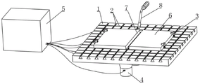
FIG. 1 is a perspective view of an ultrasonic degassing apparatus for aluminum alloy fusion welding.
FIG. 2 is a right side view of an ultrasonic degassing apparatus for aluminum alloy fusion welding.
Fig. 3 is a perspective view of the hook clip.
Fig. 4 is a half sectional view of the hook clip.
Wherein, 1, a backing plate; 2. a chute; 3. a hook-shaped clamp; 31. a slider; 32. a hook-shaped pressing block; 321. a sliding sleeve; 322. a pressing part; 323. layering; 324. a first card slot; 325. a second card slot; 33. a screw; 34. locking the nut; 341. freely rotating; 35. a spring; 4. an ultrasonic vibrator; 5. an ultrasonic generator; 6. welding parts; 7. welding seams; 8. and (4) welding the welding gun.
Detailed Description
The following description of the embodiments of the present invention is provided to facilitate the understanding of the present invention by those skilled in the art, but it should be understood that the present invention is not limited to the scope of the embodiments, and it will be apparent to those skilled in the art that various changes may be made without departing from the spirit and scope of the invention as defined and defined in the appended claims, and all matters produced by the invention using the inventive concept are protected.
As shown in fig. 1 and 2, the ultrasonic degassing device for aluminum alloy fusion welding comprises a base plate 1, wherein a plurality of sliding grooves 2 are formed in the base plate 1, a plurality of hook-shaped clamps 3 which can move along the sliding grooves 2 and can fix welding pieces are arranged in the sliding grooves 2, an ultrasonic vibrator 4 is arranged on the base plate 1, and an ultrasonic generator 5 is electrically connected to the ultrasonic vibrator 4.
As shown in fig. 3, the hook-shaped clamp 3 includes a sliding block 31 embedded in the sliding groove 2 in a sliding manner, a fastening mechanism for fixing the sliding block 31 and the sliding groove 2 at opposite positions is adjustably connected to the sliding block 31, and a hook-shaped pressing block 32 is elastically connected to the fastening mechanism. The fastening mechanism comprises a screw rod 33 in threaded connection with the sliding block 31, a locking nut 34 is sleeved on the screw rod 33 in a threaded manner, the locking nut 34 is connected with one end of a spring 35, and the other end of the spring 35 is fixedly connected to the hook-shaped pressing block 32. The spring 35 is a tension spring.
As shown in fig. 4, in order that the rotation of the locking nut 34 does not affect the direction of the hook type pressing block 32, a boss extending inward is formed on the upper portion of the inner hole of the locking nut 34, a free rotating ring 341 is inserted from the lower portion gap of the locking nut 34, a disk is fixed to the bottom end of the free rotating ring 341 to abut against the boss in the inner hole of the locking nut 34, and the top end of the free rotating ring 341 is fixedly connected with the spring 35. The upper part of the screw 33 is a polished rod and passes through the free swivel 341, the lower part of the screw 33 is processed with an external thread, the external diameter of the external thread is larger than that of the polished rod, so a step is formed between the external thread and the polished rod, a circular cavity is formed between the step and a boss on the inner hole of the locking nut 34, and a disc on the free swivel 341 is positioned in the cavity and can rotate freely. Therefore, the rotation of the lock nut 33 and the rotation of the spring 35 are independent from each other and do not affect each other, and the spring 35 is axially extended, and the upper disc of the free swivel 341 abuts against the boss in the inner hole of the lock nut 34 and can also function as an extension spring.
The section of slider 31 is trapezoidal, and spout 2 is the dovetail groove that corresponds with slider 31, and the top of dovetail groove link up with the top surface of backing plate to screw rod 33 stretches into the backing plate top. The sliding chutes 2 are distributed on the top of the backing plate 1 in a horizontal-vertical staggered manner.
The hook-shaped press block 32 includes a sliding sleeve 321 slidably sleeved on the screw 33, and a press portion 322 extending radially outward is fixed on the sliding sleeve 321. Pressing strips 323 are symmetrically fixed on two sides of the bottom surface of the pressing part 322, the height of the two pressing strips 323 is greater than 20 mm, a first clamping groove 324 is formed between the two pressing strips 323, and second clamping grooves 325 penetrating through two sides of the pressing part 322 are arranged between the two pressing strips 323 and the sliding sleeve 321.
A plurality of ultrasonic transducers 4 are mounted side by side on the bottom surface of the backing plate 1. The plurality of ultrasonic vibrators 4 are electrically connected in parallel with the ultrasonic generator 5 through wires. Be provided with the mark line that aligns with ultrasonic vibrator 4 vibration center on the top surface of backing plate 1 to when fixed weldment, can use the mark line as the reference, adjust the position of welding seam 7 to mark line directly over, on the projection of coplanar, mark the intermediate position that the line is located welding seam 7, with guarantee that welding seam position department vibration is strongest, receives ultrasonic vibration's effect best.
When two weldment 6 of needs welding, place two weldment 6 on backing plate 1 to the position of two weldment 6 of weld width adjustment according to the design, then the removal colludes the type and presss from both sides 3, collude the quantity and the fixed position that the type pressed from both sides 3 according to weldment 6 shape and size selection, for example if weldment 6 is the rectangle piece shown in figure 1, can keep away from the long limit interval of welding seam at the rectangle piece and set up two and collude the type and press from both sides 3, the broadside sets up 1 or 2 and colludes the type and press from both sides 3. After the hook-shaped clamp 3 is slid in place, the lock nut 34 is tightened, the hook-shaped pressing block 32 is pulled upwards to the position above the weldment 6, the hook-shaped pressing block 32 is released, the hook-shaped pressing block 32 is tightly pressed on the weldment 6 by means of the resilience of the spring 33, the weldment 6 is fixed on the base plate 1, then the ultrasonic generator 5 is started, and meanwhile the welding gun 8 is used for welding a welding seam 7 between the two weldments 6.
Claims (4)
1. The ultrasonic degassing device for the aluminum alloy fusion welding is characterized by comprising a base plate (1), wherein a plurality of sliding grooves (2) are formed in the base plate (1), a plurality of hook-shaped clamps (3) which can move along the sliding grooves (2) and can fix welding pieces (6) are arranged in the sliding grooves (2), ultrasonic vibrators (4) are arranged on the base plate (1), the ultrasonic vibrators (4) are arranged on the bottom surface of the base plate (1) side by side, and the ultrasonic vibrators (4) are electrically connected with an ultrasonic generator (5) in parallel through wires;
the hook-shaped clamp (3) comprises a sliding block (31) which is embedded in the sliding groove (2) in a sliding mode, a fastening mechanism which fixes the relative position of the sliding block (31) and the sliding groove (2) is connected to the sliding block (31) in an adjustable mode, the fastening mechanism comprises a screw rod (33) which is connected to the sliding block (31) in a threaded mode, and a locking nut (34) is sleeved on the screw rod (33) in a threaded mode;
a boss extending inwards is machined at the upper part of an inner hole of the locking nut (34), a free rotating ring (341) is inserted into the lower part of the locking nut (34) from a gap, a disc abutting against the boss in the inner hole of the locking nut (34) is fixed at the bottom end of the free rotating ring (341), the top end of the free rotating ring (341) is fixedly connected with one end of a spring (35), the upper part of the screw (33) is a polished rod and penetrates through the free rotating ring (341), external threads are machined at the lower part of the screw (33), the external diameter of the external threads is larger than that of the polished rod, so that a step is formed between the external threads and the polished rod, a circular cavity is formed between the step and the boss on the inner hole of the locking nut (34), and the disc on the free rotating ring (341) is positioned in the cavity and can rotate freely;
the other end fixed connection of spring (35) is on colluding type briquetting (32), collude type briquetting (32) including sliding sleeve joint sliding sleeve (321) on screw rod (33), be fixed with on sliding sleeve (321) along its radial splenium (322) that outwards extend.
2. The aluminum alloy melt welding ultrasonic degassing device according to claim 1, wherein pressing strips (323) are symmetrically fixed on two sides of the bottom surface of the pressing portion (322), the height of the two pressing strips (323) is greater than 20 mm, a first clamping groove (324) is formed between the two pressing strips (323), and second clamping grooves (325) penetrating through two sides of the pressing portion (322) are arranged between the two pressing strips (323) and the sliding sleeve (321).
3. The ultrasonic degassing device for the fusion welding of aluminum alloy according to claim 1, characterized in that a plurality of chutes (2) are distributed on the top of the backing plate (1) in a staggered manner.
4. The ultrasonic degassing device for the fusion welding of aluminum alloy according to claim 1, characterized in that the top surface of the backing plate (1) is provided with a marking line aligned with the vibration center of the ultrasonic vibrator (4).
Priority Applications (1)
| Application Number | Priority Date | Filing Date | Title |
|---|---|---|---|
| CN202010219705.8A CN111230392B (en) | 2020-03-25 | 2020-03-25 | Aluminum alloy fusion welding ultrasonic degassing device |
Applications Claiming Priority (1)
| Application Number | Priority Date | Filing Date | Title |
|---|---|---|---|
| CN202010219705.8A CN111230392B (en) | 2020-03-25 | 2020-03-25 | Aluminum alloy fusion welding ultrasonic degassing device |
Publications (2)
| Publication Number | Publication Date |
|---|---|
| CN111230392A CN111230392A (en) | 2020-06-05 |
| CN111230392B true CN111230392B (en) | 2021-03-16 |
Family
ID=70868386
Family Applications (1)
| Application Number | Title | Priority Date | Filing Date |
|---|---|---|---|
| CN202010219705.8A Active CN111230392B (en) | 2020-03-25 | 2020-03-25 | Aluminum alloy fusion welding ultrasonic degassing device |
Country Status (1)
| Country | Link |
|---|---|
| CN (1) | CN111230392B (en) |
Citations (8)
| Publication number | Priority date | Publication date | Assignee | Title |
|---|---|---|---|---|
| CN201158028Y (en) * | 2008-01-21 | 2008-12-03 | 秦磊 | Assembling workbench |
| KR20090062599A (en) * | 2007-12-13 | 2009-06-17 | 주식회사 포스코 | Fe-al different metals welding appartus and welding method using ultrarsonic vibration |
| CN201544045U (en) * | 2009-09-22 | 2010-08-11 | 广西玉柴机器股份有限公司 | Hook pressure plate clamping mechanism |
| CN103521985A (en) * | 2013-10-29 | 2014-01-22 | 南京南车浦镇城轨车辆有限责任公司 | Automatic flip-over type quick positioning and compacting device |
| CN104785926A (en) * | 2015-04-14 | 2015-07-22 | 西南交通大学 | Ultrasonic field coupled laser-MIG common welding pool aluminum alloy welding technology |
| CN105880852A (en) * | 2016-05-28 | 2016-08-24 | 长春理工大学 | Ultrasonically assisted pulse laser-MIG composite heat source welding device and welding method thereof |
| CN207735774U (en) * | 2018-01-23 | 2018-08-17 | 中山市博汇广告工艺制品有限公司 | Laser Welding word structure with clamping and positioning structure |
| CN207915048U (en) * | 2018-02-28 | 2018-09-28 | 东莞市银辰精密光电股份有限公司 | A kind of inner support packing spring chuck |
-
2020
- 2020-03-25 CN CN202010219705.8A patent/CN111230392B/en active Active
Patent Citations (8)
| Publication number | Priority date | Publication date | Assignee | Title |
|---|---|---|---|---|
| KR20090062599A (en) * | 2007-12-13 | 2009-06-17 | 주식회사 포스코 | Fe-al different metals welding appartus and welding method using ultrarsonic vibration |
| CN201158028Y (en) * | 2008-01-21 | 2008-12-03 | 秦磊 | Assembling workbench |
| CN201544045U (en) * | 2009-09-22 | 2010-08-11 | 广西玉柴机器股份有限公司 | Hook pressure plate clamping mechanism |
| CN103521985A (en) * | 2013-10-29 | 2014-01-22 | 南京南车浦镇城轨车辆有限责任公司 | Automatic flip-over type quick positioning and compacting device |
| CN104785926A (en) * | 2015-04-14 | 2015-07-22 | 西南交通大学 | Ultrasonic field coupled laser-MIG common welding pool aluminum alloy welding technology |
| CN105880852A (en) * | 2016-05-28 | 2016-08-24 | 长春理工大学 | Ultrasonically assisted pulse laser-MIG composite heat source welding device and welding method thereof |
| CN207735774U (en) * | 2018-01-23 | 2018-08-17 | 中山市博汇广告工艺制品有限公司 | Laser Welding word structure with clamping and positioning structure |
| CN207915048U (en) * | 2018-02-28 | 2018-09-28 | 东莞市银辰精密光电股份有限公司 | A kind of inner support packing spring chuck |
Also Published As
| Publication number | Publication date |
|---|---|
| CN111230392A (en) | 2020-06-05 |
Similar Documents
| Publication | Publication Date | Title |
|---|---|---|
| CN206263438U (en) | A kind of sheet material agitating friction weldering splices magic chuck | |
| CN111230392B (en) | Aluminum alloy fusion welding ultrasonic degassing device | |
| CN211759539U (en) | Aluminum alloy fusion welding ultrasonic degassing device | |
| CN218081229U (en) | Welding tool | |
| CN210756166U (en) | Fixture convenient to mount and used for steel pipe welding device for industrial machinery | |
| CN207139102U (en) | A kind of stent of ultrasonic spot welder | |
| CN218136022U (en) | Stainless steel pipe forming equipment | |
| CN113478067B (en) | Two-section type dissimilar material friction stir welding method | |
| CN207930149U (en) | A kind of agitating friction docking welding clamp | |
| CN214641311U (en) | Welding device for transformer heat dissipation plate | |
| CN220093614U (en) | Alloy material welding device | |
| CN107717198A (en) | A kind of firm easily mash welder of clamping | |
| CN216771593U (en) | Magnetic powder flaw detector | |
| CN212682765U (en) | Welding clearance adjustment mechanism | |
| CN215699403U (en) | Building pipe welding device | |
| CN211101982U (en) | Tapping device is used in screw pole processing | |
| CN213969689U (en) | Welding device for spiral pipe production line | |
| CN214518153U (en) | Ultrasonic welding equipment | |
| CN220297877U (en) | Automatic welding equipment for ultrasonic filter screen | |
| CN213827436U (en) | Efficient welding wire distribution adjustable submerged-arc welding device | |
| CN213969413U (en) | Welding head adjusting device of wire harness welding equipment | |
| CN215615901U (en) | Laser machine cutting jig fixing device | |
| CN217197041U (en) | Pipeline material welding device | |
| CN211814914U (en) | Cloth tightening device for embroidery lace of embroidery machine | |
| CN213289213U (en) | Novel assembly welding tool with positioning joint |
Legal Events
| Date | Code | Title | Description |
|---|---|---|---|
| PB01 | Publication | ||
| PB01 | Publication | ||
| SE01 | Entry into force of request for substantive examination | ||
| SE01 | Entry into force of request for substantive examination | ||
| GR01 | Patent grant | ||
| GR01 | Patent grant |