CN111220324B - Calibration device and calibration method for MEMS micro-force-torque sensor - Google Patents
Calibration device and calibration method for MEMS micro-force-torque sensor Download PDFInfo
- Publication number
- CN111220324B CN111220324B CN202010074375.8A CN202010074375A CN111220324B CN 111220324 B CN111220324 B CN 111220324B CN 202010074375 A CN202010074375 A CN 202010074375A CN 111220324 B CN111220324 B CN 111220324B
- Authority
- CN
- China
- Prior art keywords
- force
- sensor
- mems micro
- axis
- platform
- Prior art date
- Legal status (The legal status is an assumption and is not a legal conclusion. Google has not performed a legal analysis and makes no representation as to the accuracy of the status listed.)
- Active
Links
Images


Classifications
-
- G—PHYSICS
- G01—MEASURING; TESTING
- G01L—MEASURING FORCE, STRESS, TORQUE, WORK, MECHANICAL POWER, MECHANICAL EFFICIENCY, OR FLUID PRESSURE
- G01L25/00—Testing or calibrating of apparatus for measuring force, torque, work, mechanical power, or mechanical efficiency
Abstract
The invention relates to a calibration device of an MEMS micro-force-torque sensor, which is characterized by comprising a test platform, a nano-indenter arranged on the test platform, an inclined plane platform component arranged on a placing platform of the nano-indenter, an analog-digital conversion circuit connected with the MEMS micro-force-torque sensor to be tested and a sensor power supply; the inclined plane platform assembly comprises a plurality of inclined plane platform elements with different inclined plane inclination angles; the MEMS micro-force-torque sensor to be measured is a six-axis sensor and comprises a sensor body and an upright post connected with the sensor body; the sensor body is fixed on the inclined plane of the inclined plane platform element; the force application rod of the nanoindenter is aligned with the upright column in the vertical direction. Compared with the prior art, the method has the advantages of low cost, high calibration precision and the like.
Description
Technical Field
The invention relates to a calibration device and a calibration method of an MEMS micro-force-moment sensor.
Background
The contact sensor used in the robot finger is made of semiconductor material monocrystalline silicon, and comprises a hemispherical silica gel shell, a dowel bar, a base, a sensing chip, a circuit board and a wire, wherein the contact sensor can be connected to the fingertip of the robot, and the change of voltage is caused by the pressure between objects, so that force and moment are generated, and the robot can accurately take up the objects by the sensor and identify the objects. The sensor is a six-axis sensor, and applied force can be decomposed by the piezoresistive effect of the six-axis sensor to obtain components in the horizontal direction and the vertical direction, so that the voltage and the applied force can be compared. By integrating such sensor arrays on flexible substrates at high density, high performance sensors are further being manufactured, the targeted functions of such touch sensors are: the first purpose is to recognize an object to be gripped, and to obtain information on the object to be gripped only after visual information such as a dark place or a shadow of a mask cannot be obtained, shape recognition of the object in an environment, and contact of hardness, material, and the like. The second object is to obtain information for performing stable control when the robot hand grips and operates an object. Such information includes a gripping force applied to the object to be gripped, a slip generated between the object to be gripped and the hand, a moment applied to the hand by the self weight of the object to be gripped, and the like. Furthermore, the performance of an artificial tactile sensor that mimics a living organism is far from reaching the sensitivity of a living organism. However, tactile sensors generally have higher resolution than living organisms and can obtain quantitative information. This property is considered suitable for tasks that are difficult for humans to accomplish, such as medical surgery and industrial uses (especially for precision work that requires experience and skill). In addition, it is considered that even in a robot requiring human compatibility such as welfare, home, and entertainment, a tactile sensor having a flexible contact portion can be developed. The future direction is expected to be applied to array, intelligence and sensor fusion. To meet these expectations, integration of sensors and information processing technologies is indispensable, and utilization and advancement of MEMS manufacturing technologies that are increasingly compatible with semiconductor technologies are regarded as important.
Chinese patent CN101109670A discloses a three-way force sensor calibration device. The linear guide rail for X-direction translation provided with the X-direction loading mechanism and the linear guide rail for Y-direction translation provided with the Y-direction loading mechanism are fixed on the calibration workbench in a mutually orthogonal mode, two ends of the cross beam are fixed on a ball screw for lifting the cross beam, the ball screw for lifting the cross beam is vertically arranged on the calibration workbench, and the Z-direction loading mechanism is fixed on the cross beam; the standard force sensors respectively arranged on the X-direction loading mechanism, the Y-direction loading mechanism and the Z-direction loading mechanism are intersected, the positioning loading fixture clamps the calibrated three-way force sensor, the calibrated three-way force sensor is placed on the calibration workbench and positioned at the intersection point of the three sensors, and the motor drives the two ball screws for lifting the cross beam to synchronously and linearly move in the Z direction. The device is limited in practical use, firstly, the sliding beam is driven to move up and down by the rotation of the ball screws, but if the two ball screws cannot rotate synchronously, the heights of the two ends of the beam are inconsistent, so that the Z-direction loading force direction deflects, and the influence on experimental data is great; secondly, calibrating the action point of the force sensor on the loading mechanisms in the X direction, the Y direction and the Z direction to be orthogonal and one point, wherein the loading mechanisms in the three directions can only move in a single direction, but in actual use, the loading mechanisms are required to realize multidirectional movement to meet the measurement requirement, the size of the sensor is limited, and the calibration of the sensor with large size needs to be realized by moving on the basis of the device or adding a complex additional device; in the using process, the loading mechanisms in the X, Y, Z directions need to be controlled respectively, and the operation is inconvenient.
Disclosure of Invention
The invention aims to provide a calibration device and a calibration method of an MEMS micro-force-torque sensor to overcome the defects of poor precision, complex calibration process, inconvenient operation and the like in the prior art.
The purpose of the invention can be realized by the following technical scheme:
a calibration device of an MEMS micro-force-torque sensor is characterized by comprising a test platform, a nano-indenter arranged on the test platform, an inclined platform assembly arranged on a placing platform of the nano-indenter, an analog-to-digital conversion circuit connected with the MEMS micro-force-torque sensor to be tested and a sensor power supply; the inclined plane platform assembly comprises a plurality of inclined plane platform elements with different inclined plane inclination angles; the MEMS micro-force-torque sensor to be measured is a six-axis sensor and comprises a sensor body and an upright post connected with the sensor body; the sensor body is fixed on the inclined plane of the inclined plane platform element; the force application rod of the nanoindenter is aligned with the upright column in the vertical direction.
The inclined plane platform element is a cylinder with an inclined plane at the top.
The inclined plane platform element is made of aluminum materials.
The aluminum material is light and convenient, and the nano-indenter is not easy to damage.
The inclined plane platform element is fixed on a placing platform of the nano-indenter through a double-sided adhesive tape.
The sensor body is fixed on the inclined plane of the inclined plane platform element through a double-sided adhesive tape.
The fixing is completed through the double faced adhesive tape, and as the maximum force applied in the z direction of the nanoindenter is 10N, the component force of the component force divided into the inclined plane is far smaller than the friction force generated by the double faced adhesive tape, the sensor body and the inclined plane platform element cannot move in the horizontal direction.
The force application rod is sleeved with a silica gel rubber sleeve, and the top of the silica gel rubber sleeve is provided with a hemispherical first silica gel pad; a hemispherical second silica gel pad is sleeved on the upright post of the MEMS micro-force-torque sensor to be detected; the spherical surface of the first silica gel pad is in contact connection with the spherical surface of the second silica gel pad.
The invention also provides a use method of the calibration device of the MEMS micro-force-moment sensor, which comprises the following steps:
(1) placing the MEMS micro-force-moment sensor to be tested on a placing platform of a nano-indenter through a double-sided adhesive tape, starting the nano-indenter to enable a force application rod of the nano-indenter to descend, applying a force vertical to the surface of a sensor body to the sensor body through the upright post, measuring the output voltage of the MEMS micro-force-moment sensor to be tested through an analog-to-digital conversion circuit, recording the force and moment values applied by the force application rod, and drawing a change relation graph of the output pressure and the force to serve as comparison data; after the measurement is finished, the force application rod of the nanoindentor retracts and resets;
(2) taking the MEMS micro-force-moment sensor to be tested out of the placing platform, fixing the inclined plane platform element on the placing platform of the nanoindentor through a double faced adhesive tape, then fixing the sensor body on the inclined plane platform element through the double faced adhesive tape, and enabling the Y axis of the sensor body and the downward sliding direction of the inclination of the sensor body to have a phi angle, wherein the phi angle is more than 0 degree and less than 90 degrees; starting the nanoindentor to enable a force application rod of the nanoindentor to descend, applying force to the sensor body through the upright column, measuring output voltages on an X axis, a Y axis and a Z axis of the MEMS micro-force-torque sensor to be measured through the analog-to-digital conversion circuit, decomposing the force applied by the force application rod to the directions corresponding to the X axis, the Y axis and the Z axis by adopting an orthogonal decomposition method to obtain decomposition force values, and obtaining output voltages of the X axis, the Y axis and the Z axis and corresponding data of the decomposition force; after the measurement is finished, the force application rod of the nanoindentor retracts and resets;
(3) and (c) replacing the inclined plane platform elements with different inclination angles, repeating the step (b) to obtain corresponding data of different output voltages and resolving forces, and drawing a change relation graph of the system output pressure and the force in the directions corresponding to the X axis, the Y axis and the Z axis.
In the step (a) and the step (b), the descending speed of the force application rod of the nanoindenter is 0.08-0.12 mm/s, and when the force application rod reaches the target value of the applied force, the force application rod is stopped for 5 seconds and then returns.
In the step (a) and the step (b), the highest point distance between the force application rod and the inclined plane platform element is 4.5-5.5 cm when the nanoindentor is started.
The reason that the distance between the highest point height of the inclined plane platform element and the rod contraction applied by the nano-indenter is about 5CM is that sufficient observation time is provided and a certain working distance is kept.
According to the invention, by designing the platform with the inclined plane, the force in the vertical direction can be orthogonally decomposed in a coordinate system formed by an X axis, a Y axis and a Z axis of the torque sensor, so that the sensor can be loaded in the direction of X, Y, Z, three groups of data can be obtained by one-time measurement, the calibration has multidimensional property, the operation is simpler and more convenient, the measurement cost is reduced, and the precision of the calibration result is increased.
Compared with the prior art, the invention has the following advantages:
(1) by adopting a platform with an inclined plane and orthogonal decomposition of the matching force, the calibration is not limited to the Z direction, and the force can be calibrated in the X-Y-Z directions at the same time; the stress condition of the six-axis sensor is simulated more truly, and the measurement result is more accurate;
(2) the calibration results in the X-Y-Z directions are obtained simultaneously, the operation is simple, the measurement speed is high, and the calibration efficiency is improved;
(3) the force is applied by the nanoindentor, the loading process is high in precision, the loading process is stable and accurate, and the measurement precision is further improved;
(4) the hemispherical rubber is designed on the surfaces of the upright post and the force application rod, pressure is applied through the contact of the hemispherical rubber, the hard contact between the force application rod and the upright post is avoided, and the protection of the force application rod and the upright post is facilitated.
Drawings
FIG. 1 is a schematic structural view of the present invention;
FIG. 2 is an enlarged view of a portion A of FIG. 1;
FIG. 3 is a schematic structural diagram of the MEMS micro-force-moment sensor and the force application rod to be tested according to the present invention;
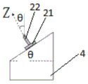
FIG. 4 is a schematic diagram of a force resolution process;
in the figure, 1 is a nanoindentor, 11 is a force application rod, 2 is a micro-force-torque sensor of an MEMS to be detected, 21 is a sensor body, 22 is an upright column, 3 is a power supply, 4 is an inclined plane platform element, 5 is an analog-digital conversion circuit, 6 is a computer, 7 is a first silica gel pad, 8 is a second silica gel pad, and theta is an included angle between the Z axis of the micro-pressure resistance-torque sensor to be detected and the vertical direction.
Detailed Description
The present invention will be described in detail with reference to specific examples. The following examples will assist those skilled in the art in further understanding the invention, but are not intended to limit the invention in any way. It should be noted that variations and modifications can be made by persons skilled in the art without departing from the spirit of the invention. All falling within the scope of the present invention.
Examples
A calibration device of an MEMS micro-force-torque sensor is shown in figure 1 and comprises a test platform, a nano-indenter 1 arranged on the test platform, an inclined plane platform assembly arranged on a placing platform of the nano-indenter 1, an analog-digital conversion circuit 5 connected with an MEMS micro-force-torque sensor 2 to be tested and a sensor power supply 3, wherein the analog-digital conversion circuit 5 is connected with a computer 6 for displaying data in aspect.
The MEMS micro-force-torque sensor 2 to be detected is a six-axis sensor and comprises a sensor body 21 and an upright post 22 connected with the sensor body 21; the sensor body 21 is fixed on the inclined plane of the inclined plane platform element 4; the force application rod 11 of the nanoindenter 1 is aligned in the vertical direction with the pillar 22. The MEMS micro-force-torque sensor 2 to be measured is composed of a PCB, a substrate, a cover, a lead, a sensor, an upright post and a silica gel shell. The sensing chip is adhered to the plastic substrate. The epoxy resin is used for adhesion, and the bonding pad of the sensing chip and the wiring of the circuit board are bonded by gold wires. The plastic housing is bonded with epoxy. The stud is epoxy bonded to the central plate of the sensor chip from the central hole of the housing, and the lid is closed. And then fixing the contact sensor on a nano-indenter.
In the embodiment, the model of the nanoindenter is an island diagram test micro compression tester HMV2000, the force application rod of the nanoindenter is made of aluminum, the strength of the aluminum is below 10n, the speed of the rod is 0.1 mm/second, and after the target force application is reached, the rod is stopped for 5 seconds and returns; the force application rod is used as a load unit to apply force to the upright post 22, and is the load unit with the maximum applicable stress of 10N and the resolution of 0.01N; the nano-indenter is connected with a computer, and the computer can display and record the force on the force application rod.
The inclined plane platform assembly comprises a plurality of inclined plane platform elements 4 with different inclined plane inclination angles, the inclined plane platform elements 4 are cylinders with inclined planes at the tops, and the inclined plane platform elements are made of aluminum materials; during measurement, the inclined plane platform element 4 is fixed on a placing platform of the nano-indenter 1 through double faced adhesive tape; the sensor body 21 is secured to the incline of the incline platform element 4 by double-sided adhesive, as shown in fig. 2. The normal direction of the inclined plane platform element 4 is the extending direction of the upright post 21 of the MEMS micro-force-torque sensor 2 to be measured and also the Z direction of the MEMS micro-force-torque sensor 2 to be measured, and the included angle between the Z axis of the micro-piezoresistive force-torque sensor to be measured and the vertical direction is an angle theta, as shown in fig. 4, the angle theta is also the included angle of the inclined plane platform relative to the horizontal plane; the method comprises the following steps of placing a sensor body 21 on an inclined plane of an inclined plane platform, enabling an X axis and a Y axis of the sensor body 21 to coincide with the X axis and the Y axis of the inclined plane platform respectively, taking the X axis and the Y axis as reference positions, rotating the sensor body 21 by a phi angle, namely enabling an included angle between horizontal rotation of the sensor body 21 and an initial X axis to be the phi angle, and enabling the sensor body 21 to have three inclined plane test states in total, wherein theta is 30 degrees and phi is 45 degrees respectively corresponding to the three inclined plane test states; θ is 30 °, Φ is 0 °; theta is 30 deg., phi is 90 deg.. A silica gel rubber sleeve is sleeved on the force application rod 11, and a hemispherical first silica gel pad 7 is arranged at the top of the silica gel rubber sleeve; a hemispherical second silica gel pad 8 is sleeved on the upright column 22 of the MEMS micro-force-torque sensor 2 to be detected; the spherical surface of the first silicone pad 7 is in contact connection with the spherical surface of the second silicone pad 8, as shown in fig. 3.
The power supply can be a 5V power supply, and provides power for the MEMS micro-force-torque sensor 2 to be detected.
The analog-to-digital conversion circuit 5 is connected between the MEMS micro-force-moment sensor 2 to be tested and the computer 6, and converts digital signals into analog signals in the form of current, voltage or charge. The Computer cannot directly process such signals, and therefore the output voltage from the sensor chip is converted from analog to digital by using a keyence analog-to-digital converter NR-250(A/D converter), and monitored by using PC, LAVIE-NX and LW40H/1(Computer) produced by NEC. And then converted into a digital signal which can be identified by a computer.
The computer 6 receives the digital signal from the analog-to-digital conversion circuit 5, and the digital signal can be converted into a line graph through the existing software, so that the output of the force can be intuitively represented in proportion to the change of the voltage.
The method for calibrating the MEMS micro-force-moment sensor by adopting the calibration device comprises the following steps:
a, placing an MEMS micro-force-torque sensor 2 to be tested on a placing platform of a nano-indenter 1 through a double-sided adhesive tape, starting the nano-indenter 1 to enable a force application rod 11 of the nano-indenter 1 to descend, enabling the distance between the force application rod 11 and the highest point of an inclined platform element 4 to be 5cm when the nano-indenter 1 is started, applying a force vertical to the surface of a sensor body 21 to the sensor body 21 through an upright post 22, measuring the output voltage of the MEMS micro-force-torque sensor 2 to be tested through an analog-to-digital conversion circuit 5, recording the force and torque values applied by the force application rod 11, and drawing a change relation graph of the output pressure and the force to serve as comparison data; after the measurement is finished, the force application rod 11 of the nanoindentor 1 retracts and resets;
b, taking the MEMS micro-force-torque sensor 2 to be tested out of the placing platform, fixing the inclined plane platform element 4 on the placing platform of the nano-indenter 1 through a double-sided adhesive tape, fixing the sensor body 21 on the inclined plane platform element 4 through the double-sided adhesive tape, starting the nano-indenter 1 to enable the force application rod 11 of the nano-indenter 1 to descend, applying force to the sensor body 21 through the upright column 22, measuring output voltages on the X axis, the Y axis and the Z axis of the MEMS micro-force-torque sensor 2 to be tested through the analog-to-digital conversion circuit 5, decomposing the force applied by the force application rod 11 to the directions corresponding to the X axis, the Y axis and the Z axis by adopting an orthogonal decomposition method to obtain decomposition force values, and obtaining output voltages of the X axis, the Y axis and the Z axis and corresponding data of the decomposition force; after the measurement is finished, the force application rod 11 of the nanoindentor 1 retracts and resets; the output voltage of the applied force of 100mN, 200mN, 300mN, 400mN is tested in sequence, each time the force of the force applying rod 11 first applies a force to the upright 22, the force applying rod 11 is set to apply a force increasing from 100mN to 500mN in steps of 100 mN.
And c, replacing the inclined plane platform element 4 with different inclination angles, repeating the step 2 to obtain different output voltages and corresponding data of the decomposition force, and drawing a change relation graph of the system output pressure and the force in the directions corresponding to the X axis, the Y axis and the Z axis.
The force applied by the force applying rod 11 is F, and the forces are respectively F in the directions corresponding to the X-axis, the Y-axis and the Z-axisx、Fy、FzThen, then


Fz=Fcosθ
The embodiment provides a novel calibration method for completing the test of the MEMS array sensor, which can be used for the multi-azimuth and multi-angle simultaneous test of the micro-force-torque sensor, and compared with the prior art, the embodiment has the following advantages: 1. the self-built test instrument is adopted, so that the device has independence, reliability and lower cost. 2. The silicon single crystal has good linear piezoresistive coefficient, and has no hysteresis and repeatability error caused by mechanical defect and strain pasting, so that the test can achieve high precision. 3. The line graph representation at the later stage of the data can more intuitively see that the change of the force and the voltage of the sensor presents linearity. 4. The use of the inclined surface enables the calibration to be not limited to the Z direction, and the magnitude of the force can be calibrated in the X-Y-Z three directions at the same time.
In conclusion, the test of the invention greatly ensures the high sensitivity and the high performance of the sensor element array, and also proves that the stress and the voltage change of the sensor are linear changes.
The foregoing description of specific embodiments of the present invention has been presented. It is to be understood that the present invention is not limited to the specific embodiments described above, and that various changes and modifications may be made by one skilled in the art within the scope of the appended claims without departing from the spirit of the invention.
Claims (9)
1. A calibration device of an MEMS micro-force-torque sensor is characterized by comprising a test platform, a nano-indenter (1) arranged on the test platform, an inclined platform component arranged on a placing platform of the nano-indenter (1), an analog-digital conversion circuit (5) connected with the MEMS micro-force-torque sensor (2) to be tested and a sensor power supply (3); the inclined plane platform component comprises a plurality of inclined plane platform elements (4) with different inclined plane inclination angles theta; the MEMS micro-force-moment sensor (2) to be detected is a six-axis sensor and comprises a sensor body (21) and an upright post (22) connected with the sensor body (21); the sensor body (21) is fixed on the inclined surface of the inclined surface platform element (4); the Y-axis direction of the sensor body (21) and the downward sliding inclination direction of the sensor body (21) on the inclined plane platform element (4) form a phi angle, 0 & lt phi & lt 90 DEG, and the force application rod (11) of the nanoindenter (1) is aligned with the upright post (22) in the vertical direction.
2. The calibration device of the MEMS micro force-torque sensor as claimed in claim 1, wherein the inclined platform element (4) is a cylinder with an inclined top.
3. The calibration device of the MEMS micro-force-torque sensor as claimed in claim 2, wherein the inclined platform element (4) is made of aluminum.
4. The calibration device of the MEMS micro-force-torque sensor as claimed in claim 1, wherein the inclined platform element (4) is fixed on the placement platform of the nanoindenter (1) by a double-sided adhesive tape.
5. The calibration device of the MEMS micro force-moment sensor as claimed in claim 1, wherein the sensor body (21) is fixed on the inclined plane of the inclined plane platform element (4) by a double-sided adhesive tape.
6. The calibration device of the MEMS micro-force-torque sensor as claimed in claim 1, wherein the force application rod (11) is sleeved with a silica gel rubber sleeve, and the top of the silica gel rubber sleeve is provided with a hemispherical first silica gel pad (7); a hemispherical second silica gel pad (8) is sleeved on the upright column (22) of the MEMS micro-force-moment sensor (2) to be detected; the spherical surface of the first silica gel pad (7) is in contact connection with the spherical surface of the second silica gel pad (8).
7. A method for calibrating a MEMS micro-force-moment sensor using the calibration apparatus of claim 1, comprising the steps of:
(a) placing the MEMS micro-force-moment sensor (2) to be tested on a placing platform of a nano-indenter (1) through a double-sided adhesive tape, starting the nano-indenter (1) to enable a force application rod (11) of the nano-indenter (1) to descend, applying a force perpendicular to the surface of the sensor body (21) to the sensor body (21) through an upright post (22), measuring the output voltage of the MEMS micro-force-moment sensor (2) to be tested through an analog-to-digital conversion circuit (5), recording the force and moment numerical values applied by the force application rod (11), and drawing a change relation graph of output pressure and force as comparison data; after the measurement is finished, the force application rod (11) of the nano-indenter (1) retracts and resets;
(b) taking the MEMS micro-force-moment sensor (2) to be tested out of the placing platform, fixing the inclined platform element (4) on the placing platform of the nanoindentor (1) through double faced adhesive tape, then the sensor body (21) is fixed on the inclined plane platform element (4) through double-sided adhesive tape, the nano-indenter (1) is started to lead the force application rod (11) of the nano-indenter (1) to descend, exerting force on the sensor body (21) through the upright column (22), measuring output voltages on an X axis, a Y axis and a Z axis of the MEMS micro-force-torque sensor (2) to be measured through the analog-to-digital conversion circuit (5), the force applied by the force applying rod (11) is decomposed to the directions corresponding to the X axis, the Y axis and the Z axis by adopting an orthogonal decomposition method to obtain a decomposition force numerical value, and corresponding data of output voltages of the X axis, the Y axis and the Z axis and the decomposition force are obtained; after the measurement is finished, the force application rod (11) of the nano-indenter (1) retracts and resets;
(c) and (c) replacing the inclined plane platform element (4) with different inclination angles, repeating the step (b) to obtain different output voltage and corresponding data of the decomposition force, and drawing a change relation graph of the system output pressure and the force in the directions corresponding to the X axis, the Y axis and the Z axis.
8. The method for calibrating the MEMS micro-force-torque sensor according to claim 7, wherein in the step (a) and the step (b), the descending speed of the force application rod (11) of the nanoindenter (1) is 0.08-0.12 mm/sec, and when the force application rod (11) reaches the target value of the applied force, the force application rod (11) is stopped for 5 seconds and then returns.
9. The method for calibrating the MEMS micro-force-torque sensor as claimed in claim 7, wherein in the step (a) and the step (b), the distance between the highest point of the force application rod (11) and the inclined platform element (4) is 4.5-5.5 cm when the nanoindenter (1) is started.
Priority Applications (1)
| Application Number | Priority Date | Filing Date | Title |
|---|---|---|---|
| CN202010074375.8A CN111220324B (en) | 2020-01-22 | 2020-01-22 | Calibration device and calibration method for MEMS micro-force-torque sensor |
Applications Claiming Priority (1)
| Application Number | Priority Date | Filing Date | Title |
|---|---|---|---|
| CN202010074375.8A CN111220324B (en) | 2020-01-22 | 2020-01-22 | Calibration device and calibration method for MEMS micro-force-torque sensor |
Publications (2)
| Publication Number | Publication Date |
|---|---|
| CN111220324A CN111220324A (en) | 2020-06-02 |
| CN111220324B true CN111220324B (en) | 2021-09-28 |
Family
ID=70827256
Family Applications (1)
| Application Number | Title | Priority Date | Filing Date |
|---|---|---|---|
| CN202010074375.8A Active CN111220324B (en) | 2020-01-22 | 2020-01-22 | Calibration device and calibration method for MEMS micro-force-torque sensor |
Country Status (1)
| Country | Link |
|---|---|
| CN (1) | CN111220324B (en) |
Families Citing this family (2)
| Publication number | Priority date | Publication date | Assignee | Title |
|---|---|---|---|---|
| CN115648285B (en) * | 2022-09-19 | 2023-07-21 | 重庆智能机器人研究院 | Zero external calibration method for robot body |
| CN115711701A (en) * | 2022-11-09 | 2023-02-24 | 上海交通大学 | Indentation-based visual touch sensor mechanical parameter in-situ calibration method |
Citations (12)
| Publication number | Priority date | Publication date | Assignee | Title |
|---|---|---|---|---|
| EP0719405A1 (en) * | 1993-09-14 | 1996-07-03 | Werner Kluft | Force-measuring device |
| JPH10160599A (en) * | 1996-12-04 | 1998-06-19 | Toyota Motor Corp | Torque detecting device |
| CN101354296A (en) * | 2008-08-04 | 2009-01-28 | 东华大学 | Fabric three-dimensional pressure simulation test system |
| CN101865737A (en) * | 2009-04-15 | 2010-10-20 | 友达光电(厦门)有限公司 | Pressure testing device and method |
| CN202562819U (en) * | 2012-04-28 | 2012-11-28 | 长沙理工大学 | Water-permeability asphalt mixture water stability testing device |
| CN203606067U (en) * | 2013-11-19 | 2014-05-21 | 广州广电计量检测无锡有限公司 | Force sensor detection support |
| CN105115840A (en) * | 2015-09-25 | 2015-12-02 | 山东交通学院 | Fatigue test device and fatigue test method for equal-thickness pavement structure on basis of MTS |
| CN106525294A (en) * | 2016-11-15 | 2017-03-22 | 中南大学 | Three-directional force calibration device and method for TBM (Tunnel Boring Machine) hob |
| CN106556516A (en) * | 2016-11-26 | 2017-04-05 | 启东锦桥轴承有限公司 | A kind of BVT noise test chargers for eliminating resonance |
| CN108534970A (en) * | 2018-06-01 | 2018-09-14 | 南京理工大学 | High-precision line slideway auxiliary Static stiffness comprehensive measurement device and method |
| CN109883611A (en) * | 2019-03-14 | 2019-06-14 | 上海交通大学 | A kind of easy force sensor caliberating device and method |
| CN209541987U (en) * | 2018-11-12 | 2019-10-25 | 中国铁道科学研究院集团有限公司铁道建筑研究所 | The caliberating device of piezoelectric pressure indicator |
Family Cites Families (2)
| Publication number | Priority date | Publication date | Assignee | Title |
|---|---|---|---|---|
| CN204314004U (en) * | 2014-11-07 | 2015-05-06 | 中国矿业大学 | A kind of construction vertical suspension rope and steady rope tension on-line measuring device |
| CN109374268A (en) * | 2018-05-02 | 2019-02-22 | 中南大学 | A kind of shield machine/TBM hob tool apron fatigue stress and life testing method and its device |
-
2020
- 2020-01-22 CN CN202010074375.8A patent/CN111220324B/en active Active
Patent Citations (12)
| Publication number | Priority date | Publication date | Assignee | Title |
|---|---|---|---|---|
| EP0719405A1 (en) * | 1993-09-14 | 1996-07-03 | Werner Kluft | Force-measuring device |
| JPH10160599A (en) * | 1996-12-04 | 1998-06-19 | Toyota Motor Corp | Torque detecting device |
| CN101354296A (en) * | 2008-08-04 | 2009-01-28 | 东华大学 | Fabric three-dimensional pressure simulation test system |
| CN101865737A (en) * | 2009-04-15 | 2010-10-20 | 友达光电(厦门)有限公司 | Pressure testing device and method |
| CN202562819U (en) * | 2012-04-28 | 2012-11-28 | 长沙理工大学 | Water-permeability asphalt mixture water stability testing device |
| CN203606067U (en) * | 2013-11-19 | 2014-05-21 | 广州广电计量检测无锡有限公司 | Force sensor detection support |
| CN105115840A (en) * | 2015-09-25 | 2015-12-02 | 山东交通学院 | Fatigue test device and fatigue test method for equal-thickness pavement structure on basis of MTS |
| CN106525294A (en) * | 2016-11-15 | 2017-03-22 | 中南大学 | Three-directional force calibration device and method for TBM (Tunnel Boring Machine) hob |
| CN106556516A (en) * | 2016-11-26 | 2017-04-05 | 启东锦桥轴承有限公司 | A kind of BVT noise test chargers for eliminating resonance |
| CN108534970A (en) * | 2018-06-01 | 2018-09-14 | 南京理工大学 | High-precision line slideway auxiliary Static stiffness comprehensive measurement device and method |
| CN209541987U (en) * | 2018-11-12 | 2019-10-25 | 中国铁道科学研究院集团有限公司铁道建筑研究所 | The caliberating device of piezoelectric pressure indicator |
| CN109883611A (en) * | 2019-03-14 | 2019-06-14 | 上海交通大学 | A kind of easy force sensor caliberating device and method |
Non-Patent Citations (2)
| Title |
|---|
| 《航向测量系统中三轴磁传感器标定的等效两步法》;石岗等;《仪器仪表学报》;20170228;402-407 * |
| 《钢轨轮廓全断面高精度动态视觉测量方法研究》;占栋等;《铁道学报》;20150930;96-106 * |
Also Published As
| Publication number | Publication date |
|---|---|
| CN111220324A (en) | 2020-06-02 |
Similar Documents
| Publication | Publication Date | Title |
|---|---|---|
| Kim et al. | A novel six-axis force/torque sensor for robotic applications | |
| CN111220324B (en) | Calibration device and calibration method for MEMS micro-force-torque sensor | |
| KR102189054B1 (en) | Retroreflective multi-axis force torque sensors | |
| US9869597B1 (en) | Compound strain gage carrier for multi-axis force/torque sensing | |
| Suwanratchatamanee et al. | Robotic tactile sensor system and applications | |
| Vogt et al. | A soft multi-axis force sensor | |
| Kim et al. | Design of flexible tactile sensor based on three-component force and its fabrication | |
| Lincoln et al. | An optical 3D force sensor for biomedical devices | |
| Xi et al. | A flexible tactile sensor array based on pressure conductive rubber for three-axis force and slip detection | |
| Zhou et al. | A force decoupling method for simultaneously measuring vertical and shear force | |
| Wang et al. | A flexible tactile sensor array based on pressure conductive rubber for contact force measurement and slip detection | |
| Fiedler et al. | A low-cost modular system of customizable, versatile, and flexible tactile sensor arrays | |
| Black et al. | Towards differential magnetic force sensing for ultrasound teleoperation | |
| Zhao et al. | A tri-axial touch sensor with direct silicon to PC-board packaging | |
| CN114235230B (en) | Flexible six-dimensional force sensor based on mortise and tenon structure | |
| Kim et al. | Displacement sensor integrated into a remote center compliance device for a robotic assembly | |
| Zhang et al. | SkinCell: A Modular Tactile Sensor Patch for Physical Human–Robot Interaction | |
| Kawashima et al. | Shear-force sensor with point-symmetric electrodes driven by LTPS TFT active matrix backplane | |
| Park et al. | Three-Axis Flat and Lightweight Force/Torque Sensor for Enhancing Kinesthetic Sensing Capability of Robotic Hand | |
| Li et al. | F-touch sensor for three-axis forces measurement and geometry observation | |
| Morton et al. | Soft 3-Axis Capacitive Force Sensor for Robotic E-Skin on Curved Surfaces | |
| CN112284438A (en) | Multifunctional finger sensor calibration tool | |
| Peng et al. | Modular artificial tactile receptors based on mechanical field sensing | |
| Drimus et al. | Novel approaches for bio-inspired mechano-sensors | |
| Kaneta et al. | Redesigned microcantilevers for sensitivity improvement of microelectromechanical system tactile sensors |
Legal Events
| Date | Code | Title | Description |
|---|---|---|---|
| PB01 | Publication | ||
| PB01 | Publication | ||
| SE01 | Entry into force of request for substantive examination | ||
| SE01 | Entry into force of request for substantive examination | ||
| GR01 | Patent grant | ||
| GR01 | Patent grant |