CN111214190A - Washing type dirt-removing separating electric mop cleaning tool - Google Patents
Washing type dirt-removing separating electric mop cleaning tool Download PDFInfo
- Publication number
- CN111214190A CN111214190A CN202010187523.7A CN202010187523A CN111214190A CN 111214190 A CN111214190 A CN 111214190A CN 202010187523 A CN202010187523 A CN 202010187523A CN 111214190 A CN111214190 A CN 111214190A
- Authority
- CN
- China
- Prior art keywords
- mop
- electric mop
- cleaning
- electric
- area
- Prior art date
- Legal status (The legal status is an assumption and is not a legal conclusion. Google has not performed a legal analysis and makes no representation as to the accuracy of the status listed.)
- Pending
Links
Images


Classifications
-
- A—HUMAN NECESSITIES
- A47—FURNITURE; DOMESTIC ARTICLES OR APPLIANCES; COFFEE MILLS; SPICE MILLS; SUCTION CLEANERS IN GENERAL
- A47L—DOMESTIC WASHING OR CLEANING; SUCTION CLEANERS IN GENERAL
- A47L13/00—Implements for cleaning floors, carpets, furniture, walls, or wall coverings
- A47L13/10—Scrubbing; Scouring; Cleaning; Polishing
- A47L13/50—Auxiliary implements
- A47L13/58—Wringers for scouring pads, mops, or the like, combined with buckets
Landscapes
- Cleaning Implements For Floors, Carpets, Furniture, Walls, And The Like (AREA)
Abstract
The invention discloses a washing type dirt-cleaning separation electric mop cleaning tool, which comprises an electric mop and a mop bucket, wherein the mop bucket comprises a clean water area and a sewage area which are mutually independent, a dry area separated from the clean water area is arranged above the clean water area, a washing component used for cleaning a wiping object is arranged in the dry area, a channel communicated with the sewage area is arranged in the dry area, a water pumping device is arranged in the clean water area, water in the clean water area can be pumped out and sprayed on the wiping object to be cleaned through the work of the water pumping device, sewage generated by cleaning and dewatering can flow into the sewage area, the separation of the clean water and the sewage is realized, and the electric mop can be washed by clean water and dewatered in the dry area without water, has a better cleaning effect and is convenient and rapid to use.
Description
Technical Field
The invention belongs to the technical field of cleaning supplies, and particularly relates to an electric mop cleaning tool.
Background
Along with the continuous improvement of the living standard of people and the continuous improvement of the quality requirements of people on life, the household cleaning articles are also gradually developed from a manual tool to the automation direction, and the birth of the electric mop is also because of the household cleaning articles, the electric mop not only reduces the labor capacity of people, but also has better cleaning effect;
the existing electric mop has the following application numbers: 201911043447.6 discloses an electric mop and a mop bucket kit, wherein the mop bucket can not be separated during cleaning and dewatering, that is, the electric mop is in the same environment during cleaning and dewatering, either immersed in water or in a water-free state, and the user often only uses the mop bucket to clean when using, and the dewatering can be manually taken up to be separated from the drying or dried in other places, so the use is very inconvenient; and the mop bucket in the prior art also does not realize the separation of clear water and sewage, liquid is completely concentrated in one position in the mop bucket, and after the mop is dried, although the surface of a wiping object is cleaner, the mop bucket is dried after being rinsed in sewage, so that the temporary solution and the permanent solution are not treated.
Disclosure of Invention
The invention mainly solves the technical problem of providing a washing type dirt-cleaning separation electric mop cleaning tool, water in a clean water area can be pumped out through the work of a water pumping device and sprayed on a wiping object for cleaning, sewage generated by cleaning and dehydration can flow into a sewage area, the separation of clean water and sewage is realized, and the electric mop can be washed by clean water and dehydrated in a dry area without water, has a better cleaning effect and is convenient and fast to use.
In order to solve the above technical problems, one technical solution adopted by the present invention is as follows:
the utility model provides a washing type cleans dirty separation electric mop burnisher, includes electric mop and mop bucket, electric mop includes mop pole and mop head, be equipped with on the mop head by the rotatory wiper of motor drive, the mop bucket is including mutual independent clear water district and sewage district, the top in clear water district be equipped with clear water district divided dry district, be equipped with in the dry district and be used for the cleanness the washing part of wiper, dry district is equipped with the intercommunication the passageway in sewage district, clear water district is equipped with pumping device.
Further, when the water pumping device works, water in the clean water area can be pumped out and sprayed on the wiper for cleaning, and sewage generated by cleaning is adsorbed on the wiper or flows into the sewage area through the channel; when the water pumping device stops working or no water exists in the clean water area, the mop head rotates to dewater, and sewage generated by dewatering flows into the sewage area through the channel.
Furthermore, the water pumping device is provided with a linkage part penetrating to the dry area, and when the electric mop is arranged in the dry area, the mop head of the electric mop can be clamped with the linkage part, so that the water pumping device is driven to work by a motor of the electric mop.
Further, pumping device includes driving tooth and impeller pump, linkage portion fixed connection in driving tooth or with driving tooth structure as an organic whole, impeller pump be equipped with the driven tooth that driving tooth meshed, the number of teeth of driving tooth is greater than the number of teeth of driven tooth.
Further, the dry area is provided with a supporting part for supporting the electric mop, and the electric mop is abutted against the supporting part and has a high position and a low position;
when the electric mop is positioned at the low position, the mop head is clamped with the linkage part, and the water pumping device is driven by the motor of the electric mop to pump water to flush the mop; when the mop head is positioned at the high position, the mop head is separated from the linkage part, the water pumping device stops, and the electric mop is rotated to dewater.
The mop head is provided with a rotary disc for mounting the wiping materials, the rotary disc is driven by a motor to rotate, the linkage part is a rod-shaped linkage shaft, the rotary disc is provided with a linkage hole for inserting the linkage shaft, and the linkage part is circumferentially stopped after being inserted into the linkage hole.
Further, the mop bucket comprises a first bucket body and a second bucket body, the first bucket body is provided with the separated clean water area and the separated sewage area, and the second bucket body is positioned above the first bucket body and forms the dry area;
or, the mop bucket comprises a first bucket body and a second bucket body, the second bucket body is contained in the first bucket body, the first bucket body forms the sewage area, the second bucket body is of a double-layer structure, the lower layer of the second bucket body is the clean water area, and the upper layer of the second bucket body is the dry area.
Further, the scrubbing means includes at least one of a washing brush, a washing blade, or a washing roller.
Furthermore, the dry area is provided with a plurality of water spraying ports, all the water spraying ports are distributed below the wiping object when the electric mop is inserted into the cleaning device for cleaning, and the water spraying ports are communicated with the water outlet of the water pumping device.
Further, the wipes of the electric mop have at least two rotational speeds.
The supporting part comprises a high-position supporting part fixedly arranged on the mop bucket, and when the electric mop is abutted against the high-position supporting part, the electric mop is positioned at the high position; when the electric mop is abutted against the washing component, the electric mop is positioned at the low position;
or the supporting part comprises a high-position supporting part and a low-position supporting part which are fixedly arranged on the mop bucket, and the electric mop can be respectively abutted against the high-position supporting part and the low-position supporting part.
Furthermore, the lifting device is further provided, the supporting part is arranged on the lifting device, and the supporting part can be located at the high position or the low position through the lifting device.
Furthermore, the lifting device comprises a fixed seat and a lifting column, and the upper end of the lifting column is the supporting part;
the fixed seat is fixedly connected with the mop bucket, the lifting columns are connected with the fixed seat in a penetrating and sleeving manner and can slide along the axial direction of the lifting columns and rotate along the circumferential direction of the lifting columns, high-position steps are arranged on the side wall of the fixed seat and are uniformly distributed along the circumferential direction of the side wall, a low-position step is further arranged between every two adjacent high-position steps, and a positioning block capable of being arranged on the high-position step or the low-position step is arranged on the side wall of each lifting column;
the mop head is provided with a positioning hole into which the upper end of the lifting column can be inserted, and a clamping structure capable of clamping the lifting column and driving the lifting column to ascend is arranged in the positioning hole.
Furthermore, the low-position steps are the bottom of the mop bucket, and a channel for the positioning block to slide is arranged between the adjacent high-position steps.
Furthermore, the fixing seat is provided with a ratchet, the tooth end of the ratchet is arranged downwards, the upper surface of the positioning block is an inclined plane, when the lifting column rises, the inclined plane is abutted to the ratchet and can drive the lifting column to rotate, and the positioning block can sequentially fall into the high-level step and the low-level step through the rising rotation of the lifting column at each time.
Furthermore, the clamping structure is a protrusion which is arranged on the side wall of the positioning hole, extends towards the positioning hole, and has elasticity, and the clamping action is completed through the elastic protrusion.
Furthermore, the lifting device comprises a supporting column, the upper end of the supporting column is the supporting part, the supporting column or the mop head is also provided with an elastic part, and the elasticity of the elastic part is greater than the weight of the electric mop;
when in use, the electric mop is placed on the supporting part and driven to be positioned at the high position by the elastic part for dewatering; the electric mop is pressed down to overcome the elasticity of the elastic part so that the electric mop is positioned at the low position for cleaning.
Further, the support column is arranged on the mop bucket and can move along the axial direction of the support column, the elastic component is located between the support column and the mop bucket, and the elastic component drives the support column to move towards the direction far away from the mop bucket.
The upper end of the supporting column is provided with the linkage part, the lower part of the supporting column is positioned in the clean water area, and the lower part of the supporting column is provided with a driving tooth capable of driving the water pumping device to work;
when the supporting column supports the electric mop to be positioned at a high position, the driving teeth are separated from the water pumping device, and the electric mop is rotated to dewater; and pressing the electric mop downwards to enable the supporting column to descend to a low position, wherein the driving teeth are meshed with the water pumping device, and the water pumping device works to clean the electric mop.
Furthermore, the support column is fixedly arranged on the mop barrel, the mop head is provided with a telescopic part, the elastic component is positioned between the telescopic part and the mop head, and the acting force of the elastic component drives the telescopic part to move towards the direction far away from the mop head.
Furthermore, the mop head is provided with a positioning groove matched with the supporting part, and the supporting part can be accommodated in the positioning groove.
The lifting device comprises a slide for limiting the movement track of the electric mop, the slide is arranged on the mop barrel or the electric mop and is provided with a high-position supporting part and a low-position supporting part, the electric mop can move to the high-position supporting part or the low-position supporting part along the track of the slide, and the slide is also provided with a blocking part for switching the falling position of the mop head;
the electric mop can fall into the high-position supporting part or the low-position supporting part when moving downwards, and can block the upward movement of the electric mop through the blocking part when moving upwards, and the downward movement direction of the electric mop can be switched through the blocking part.
Furthermore, the slide way is positioned on the side wall of the mop barrel, the side wall of the mop head is provided with a slide column which can be contained in the slide way, and an opening of the slide way for the slide column to enter is arranged upwards;
or the slide way is positioned on the side wall of the mop head, the side wall of the mop bucket is provided with a slide post which can be contained in the slide way, and an opening of the slide way for the slide post to enter is arranged downwards.
The invention has the beneficial effects that:
the cleaning tool is provided with a water pumping device, the water pumping device can pump water in the clean water area and spray the water on the wiper for cleaning, and sewage generated by cleaning is adsorbed on the wiper or flows into the sewage area through the channel; when the water pumping device stops working or no water exists in the clean water area, the mop head rotates to dewater, sewage generated by dewatering flows into the sewage area through the channel, so that the clean water and the sewage are separated, and the electric mop can be flushed by clean water and dewatered in a dry area without water, has a good cleaning effect and is convenient and quick to use;
the electric mop is lifted to form the clutch with the water pumping device, so that the water pumping device is turned on or turned off, namely, the mop is driven to work to pump water and flush when being positioned at a low position, and is separated from the water pumping device when being positioned at a high position, so that the mop is dewatered, the operation logic is very simple and clear, and the use is also very convenient;
the supporting part is arranged on the lifting device, the supporting part can be positioned at a high position or a low position through the lifting device, the operation logic is very simple, the seamless switching between cleaning and dewatering can be realized only by lifting or pressing, the redundant operation of a user is not needed, the higher learning cost is not needed, and the use is very convenient.
The foregoing description is only an overview of the technical solutions of the present invention, and in order to make the technical solutions of the present invention more clearly understood and to implement them in accordance with the contents of the description, the following detailed description is given with reference to the preferred embodiments of the present invention and the accompanying drawings.
Drawings
FIG. 1 is a schematic view showing the overall structure of a cleaning tool in embodiment 1;
FIG. 2 is an exploded view of the cleaning tool in embodiment 1;
FIG. 3 is a schematic view showing the structure of the electric mop in embodiment 1;
FIG. 4 is a schematic view showing the structure of a brush means in embodiment 1;
FIG. 5 is a schematic structural view of the water pumping device in example 1;
FIG. 6 is a schematic view showing the overall structure of a cleaning tool according to embodiment 2;
FIG. 7 is a sectional view of the elevating device in embodiment 2;
FIG. 8 is a view in the direction A of FIG. 6 (the mop in the raised position);
FIG. 9 is a view taken along line A of FIG. 6 (with the mop in the lowered position);
FIG. 10 is a view of section B of FIG. 8 (a cross-sectional view of the clamping structure);
FIG. 11 is a sectional view of another holding structure in embodiment 2;
FIG. 12 is a schematic view showing the overall construction of a cleaning tool according to embodiment 3;
FIG. 13 is a schematic structural view of a lifting device in embodiment 3;
FIG. 14 is a schematic structural view of a holder according to embodiment 3;
FIG. 15 is a schematic view of a holding structure in embodiment 3;
FIG. 16 is a first construction schematic view of a cleaning tool according to embodiment 4;
FIG. 17 is a sectional view of the elevating device in the first structure of embodiment 4;
FIG. 18 is a second construction schematic view of the cleaning tool of embodiment 4;
FIG. 19 is a schematic view showing the construction of a lifting device in a second construction according to embodiment 4;
FIG. 20 is a schematic view showing a third construction of the cleaning tool of embodiment 4;
FIG. 21 is an enlarged view of section C of FIG. 20;
FIG. 22 is an exploded perspective view of a first structure of a cleaning tool according to embodiment 5;
FIG. 23 is a schematic view showing a slide sliding locus in embodiment 5;
FIG. 24 is a schematic view showing a slide sliding locus (another stopper) in example 5;
FIG. 25 is an exploded perspective view of a second structure of a cleaning tool according to embodiment 5;
Detailed Description
The following detailed description of the preferred embodiments of the present invention, taken in conjunction with the accompanying drawings, will make the advantages and features of the invention easier to understand by those skilled in the art, and thus will clearly and clearly define the scope of the invention.
Example 1:
a rinse-off dirt-cleaning separating electric mop cleaning tool, as shown in fig. 1 and 2: including electronic mop 1 and mop bucket 2, electronic mop includes mop pole 11 and mop head 12, be equipped with on the mop head by the rotatory wiping thing 13 of motor drive, its characterized in that: the mop bucket comprises a clean water area 21 and a sewage area 22 which are mutually independent, a dry area 25 separated from the clean water area is arranged above the clean water area, a washing and brushing part 3 used for cleaning the wiping matters is arranged in the dry area, and a channel 251 communicated with the sewage area is arranged in the dry area;
the clean water area is provided with a water pumping device 6, the water pumping device can pump water in the clean water area and spray the water on the wiper for cleaning, and sewage generated by cleaning is adsorbed on the wiper or flows into the sewage area through the channel; when the water pumping device stops working or no water exists in the clean water area, the mop head rotates to dewater, and sewage generated by dewatering flows into the sewage area through the channel.
According to the cleaning tool, two ways of dewatering the electric mop are provided, namely starting and stopping control of the water pumping device is realized, water in the cleaning area is used as a disposable consumable, and when the water in the clean water area is used up, the electric mop can enter a dewatering state after continuously rotating, or the two ways are combined; the water pumping device can be driven by a motor, a person (such as stepping) or an electric mop, and the like.
In the embodiment, the water pumping device is driven by the electric mop, and the cleaning state and the dehydration state are switched by controlling the starting and stopping of the water pumping device;
the mop comprises a dry area, a water pumping device, a mop head, a linkage part, a channel and a channel, wherein the dry area is provided with a supporting part for supporting the electric mop, the electric mop is abutted against the supporting part and has a high position and a low position, the water pumping device is provided with the linkage part 61 penetrating to the dry area, when the electric mop is positioned at the low position, the mop head is clamped with the linkage part, the water pumping device is driven by a motor to pump water in a clean water area and spray the water on a wiper for cleaning, and sewage generated by cleaning is adsorbed on the wiper or flows into a sewage area through the channel;
when the mop head is positioned at the high position, the mop head is separated from the linkage part, the mop head is rotated to dewater, and sewage generated by dewatering flows into the sewage area through the channel.
The electric mop of the present invention is provided with a driving motor for driving the wiping material to rotate, and the type of the electric mop is not limited, and the electric mop can be a rotary head type flat mop, a rotary belt mop and/or a horizontal roller type rotary mop, and in the present embodiment, as shown in fig. 3: the electric mop is an electric flat mop, the mop head is provided with a rotary disc 126 for installing the wiping material, and the rotary disc is driven by a motor to rotate;
in the invention, the wiping object is detachably connected to the turntable through a magic tape;
in this embodiment, the linkage structure is as shown in fig. 2 and 3: the linkage part is a rod-shaped linkage shaft, the turntable is provided with a linkage hole 127 into which the linkage shaft can be inserted, and the linkage part is circumferentially stopped after being inserted into the linkage hole.
As shown in fig. 2: the mop bucket comprises a first bucket body 23 and a second bucket body 24, the first bucket body is provided with the separated clean water area and sewage area, and the second bucket body is positioned above the first bucket body and forms the dry area;
or, the mop bucket comprises a first bucket body 23 and a second bucket body 24, the second bucket body is accommodated in the first bucket body, the first bucket body forms the sewage area, the second bucket body is of a double-layer structure, the lower layer of the second bucket body is the clean water area, and the upper layer of the second bucket body is the dry area;
that is to say, the clean water area and the sewage area share one barrel body and one barrel body with the dry area respectively, but the embodiment adopts a double-barrel structure, so that the manufacture and assembly of the mop barrel are facilitated, and the first barrel body and the second barrel body which are stacked up and down can be detached and cleaned conveniently by a user;
however, the structure is not limited to the above, for example, only one mop bucket is provided with a sewage area and a clean water area, a detachable plate-shaped part is arranged above the clean water area and is placed above the clean water area so as to be divided into independent dry areas, and the structure is actually the same as the embodiment, and only the bucket body is distinguished and replaced by a partition plate;
the embodiment adopts a double-barrel structure, and the clean water area and the sewage area share one barrel body respectively.
In this embodiment, the brushing component is disposed at the bottom of the second barrel, the second barrel not only covers the clean water region, but also covers the dirty water region, and the channel for draining water is a through hole disposed at the bottom of the second barrel and above the dirty water region.
As shown in fig. 4: the brushing means includes at least one of a washing brush 32, a washing blade 33, or a washing roller 34;
the washing means may comprise any washing device in the prior art, such as a washing brush, a washing roller, etc., and as is well known, mop wipers are various in variety, such as flat cloth mops, plate-shaped or brush-shaped washing means are good in washing effect, such as a plurality of strip-shaped wipers, and it is reasonable to directly rotate and wash in water, such as collodion mops (sponge, foam cotton), and washing brushes or washing rollers are used, so that the washing members arranged on the washing disc are various in combination, and the invention is only exemplified by a few typical modes.
The washing and brushing part is fixedly connected with the mop barrel, is in a fixed state when the mop is washed, and performs cleaning operation through the rotation of the electric mop wiper;
of course, the scrubbing means may be positively rotatable in a direction opposite to that of the power mop wipe.
As shown in fig. 4: the dry area is provided with a plurality of water spraying nozzles 31, all the water spraying nozzles are arranged and distributed below the wiping object when the electric mop is inserted into the cleaning device for cleaning, and the water spraying nozzles are communicated with the water outlet of the water pumping device.
In this embodiment, the dry area is provided with a water collecting cavity, the water collecting cavity is of a structure with a cavity and is communicated with a water outlet of the water pumping device, and all water spraying ports are distributed on the wall of the water collecting cavity.
As shown in fig. 5: the water pumping device comprises a driving gear 62 and an impeller pump 63, water pumped by the impeller pump is sprayed to a dry area (wiping material) through a pipeline 64, a linkage part is fixedly connected with the driving gear or is in an integral structure with the driving gear, the impeller pump is provided with a driven gear 631 meshed with the driving gear, the number of the driving gear is greater than that of the driven gear, namely, the transmission ratio of the driving gear to the driven gear is greater than 1, the rotating speed of the impeller pump can be increased, so that the flow of the water pump is increased, the preferred transmission ratio is 2-3, and in the embodiment, the transmission ratio of the gear is 2.4.
The impeller pump of the present invention is a centrifugal impeller pump which can be made thin, thereby reducing the overall volume of the mop bucket.
The wipes of the electric mop have at least two rotational speeds; one of the two speeds is the rotating speed during mopping and cleaning, the other one is the rotating speed during dehydration, and the higher rotating speed can improve the dehydration effect;
three speeds can be set, and the three speeds respectively correspond to mopping, cleaning and dewatering, so that the effect of each function is better.
The embodiment realizes the structure that the electric mop can be respectively positioned at the high position and the low position as shown in figures 1 and 2: the supporting part comprises a high-position supporting part 35 fixedly arranged on the mop bucket, and when the electric mop is abutted against the high-position supporting part, the electric mop is positioned at the high position; when the electric mop is abutted against the washing component, the electric mop is positioned at the low position;
or the supporting part comprises a high supporting part 35 and a low supporting part 36 which are fixedly arranged on the mop bucket, and the electric mop can be respectively abutted against the high supporting part and the low supporting part.
In this embodiment, the high-position support portion 35 and the low-position support portion 36 are located on the inner side wall of the mop bucket, the electric mop has a positioning portion 123 capable of abutting against the high-position support portion or the low-position support portion, when in use, the electric mop is manually operated, the position of the electric mop can be selected according to requirements, the switching is also performed through manual operation of a user, the electric mop can be rotationally dewatered when being placed on the high-position support portion, when the electric mop is placed on the low-position support portion or directly placed on a washing component, the mop head can be clamped with the linkage portion, the water pumping device is driven to work through a motor of the electric mop, and water spraying, washing and cleaning operations are performed;
the high-level and low-level implementation mode is simple, other structures are not needed, the preparation cost is low, and the damage is not easy to occur.
In addition, when the clear water in the clear water area is pumped and water needs to be injected into the clear water area again, the water injection mode is various, for example, an external water tank, an external water pipe and a faucet are arranged, or simple manual water injection is carried out, and the water injection control can be completed through an automatic device such as an electromagnetic valve.
Example 2:
the present embodiment is different from embodiment 1 in that: the electric mop can be positioned at a high position and a low position;
the cleaning tool is also provided with a lifting device 4, the supporting part is arranged on the lifting device, and the supporting part can be positioned at the high position or the low position through the lifting device, so that the electric mop abutted against the supporting part has the high position and the low position.
As shown in fig. 6 to 9: the lifting device comprises a fixed column 41, a moving tube 42 and a positioning rod 43, the fixed column is fixedly connected to the mop bucket, the moving tube is sleeved outside the fixed column, the positioning rod passes through the moving tube and is inserted into an insertion hole in the center of the fixed column, the positioning rod and the fixed column are relatively stopped rotating, and the upper end of the positioning rod is a supporting part;
the fixed column is sleeved with a transmission piece 44, the transmission piece is in spiral connection transmission with the moving pipe, the moving pipe can move up and down to drive the transmission piece to rotate, and a ratchet structure 441 capable of being meshed is arranged between the transmission piece and the moving pipe;
a rotation stopping structure 431 is arranged between the inner peripheral surface of the moving pipe and the positioning rod, and the positioning rod can move along the axial direction of the positioning rod, so that the rotation stopping structure can be engaged or disengaged;
when the movable pipe is meshed with the fixed column, the movable pipe and the positioning rod are circumferentially stopped, and the positioning rod and the fixed column are circumferentially stopped, so that the movable pipe cannot rotate at the moment, and when the movable pipe is separated from the fixed column, the movable pipe can rotate;
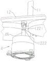
the mop head is provided with a positioning hole 121 for inserting the upper end of the moving pipe, and a clamping structure 122 capable of clamping the moving pipe and driving the moving pipe to ascend is arranged in the positioning hole.
When the lifting device is in a normal state, the moving pipe and the positioning rod are both positioned at the low position, the electric mop is abutted against the positioning rod (or directly abutted against the washing component), and the mop head is clamped with the linkage part at the moment, the electric mop is started, and the water pumping device is rotationally driven to work to spray water to the wiping objects and scrape and clean the wiping objects with the washing component;
when the dewatering operation is required after cleaning, the electric mop is lifted, the clamping structure and the moving pipe are clamped to drive the moving pipe to move upwards, the positioning rod is driven to move upwards in the continuous upward movement process, the rotation stopping structure is engaged after the positioning rod moves upwards, and the ratchet structure of the transmission part is engaged, so that the moving pipe cannot rotate at the moment (the moving mode of the moving pipe can only rotate due to the spiral connection mode between the moving pipe and the transmission part, and the moving pipe moves up and down due to rotation), therefore, the moving pipe cannot move up and down, the moving pipe (and the positioning rod) is kept at a high position, and the electric mop is kept at the high position;
after the dewatering operation is finished, the electric mop is separated from the lifting device, at the moment, the moving pipe is not clamped by the mop head, and can slightly fall by one end distance (the falling distance is the distance for enabling the rotation stopping structure to be disengaged from the occlusion), so that the rotation stopping structure is disengaged, and at the moment, the moving pipe can rotate and fall until the normal state is recovered.
The clamping structure is shown in fig. 10 and 11: the clamping device comprises an elastic protruding part 1221 which is arranged on the side wall of the positioning hole and extends towards the inside of the positioning hole, and clamping action is completed through the elastic protruding part;
the elastic protrusion may be a snap structure realized by the elasticity of the material thereof, as shown in fig. 10: the protruding part is of an integral structure and has elasticity, and the clamped part is provided with a flange or a concave ring 1222 matched with the protruding part;
it is also possible as shown in fig. 11: the elastic member 1223 drives the holding head 1224 to protrude into the positioning hole, thereby achieving elastic holding.
In the embodiment, in consideration of the height of the lifting device and the overall height of the mop bucket, the lifting device is arranged in the clean water area and extends out of the clean water area to the dry area, so that the height of the mop bucket can be reduced to the maximum extent, the volume of the mop bucket is reduced, the mop bucket is lighter and the cost can be reduced; but actually, the lifting device can also be arranged in the upper dry area, and at the moment, because the lifting stroke of the lifting device needs to be ensured, the whole height of the mop bucket is inevitably increased by arranging the lifting device in the dry area under the same stroke.
The lifting device of the embodiment can realize coaxial lifting and positioning of the mop in the mop bucket, so that the mop can be cleaned at a low position, the mop is lifted to a position above the water level through the lifting mechanism after being cleaned to be dewatered, and the cleaning and dewatering are coaxially performed, so that the cleaning and dewatering water are combined into one and are coaxially performed, the structure is simplified, the operation is convenient and fast, the volume of the mop bucket can be reduced, the packaging, the transportation, the storage and the storage are convenient, and the use is more labor-saving; the lifting mechanism is simple in structure, easy to manufacture and assemble, low in cost and beneficial to market popularization.
The structure of the lifting device in this embodiment is disclosed in chinese patent application No. 201810014543.7.
Example 3:
the present embodiment is different from embodiment 2 in the structure of the lifting device, as shown in fig. 12 to 14: the lifting device comprises a fixed seat 45 and a lifting column 46, and the upper end of the lifting column is the supporting part;
the fixed seat is fixedly connected with the mop bucket, the lifting columns are connected with the fixed seat in a penetrating and sleeving manner and can slide along the axial direction of the lifting columns and rotate along the circumferential direction of the lifting columns, high steps 451 are arranged on the side wall of the fixed seat and are uniformly distributed along the circumferential direction of the side wall, a low step 452 is further arranged between every two adjacent high steps, and a positioning block 461 capable of being arranged on the high step or the low step is arranged on the side wall of each lifting column;
like embodiment 2, the mop head has a positioning hole 121 for inserting the upper end of the lifting column, and a clamping structure 122 is arranged in the positioning hole and can clamp the lifting column and drive the lifting column to ascend.
This embodiment is shown in fig. 15: the clamping structure is a mutually matched buckling structure, a protruding part 1221 is arranged in the positioning hole, and a concave ring 1222 for clamping the protruding part is arranged on the periphery of the lifting column;
when the electric mop is abutted against the supporting part, the lifting column can be driven to ascend by clamping the lifting column through the clamping structure, positioning blocks on the lifting column can be respectively arranged on the high-position step or the low-position step, so that the electric mop can be positioned at the low position for cleaning and positioned at the high position for dewatering, and when the electric mop is positioned at the low position, the linkage hole 127 on the mop head is meshed with the linkage part 61, so that the water pumping device is driven to work, and water is sprayed towards the wiping matters of the electric mop;
in this embodiment, the lifting column penetrates through the fixing seat, the high-order step and the low-order step are disposed on the inner side wall of the fixing seat, and the positioning blocks are disposed on the outer side wall of the lifting column.
In addition, in consideration of the height of the lifting device and the overall height of the mop bucket, the lifting device is arranged in the clean water area, so that the size of the mop bucket is reduced, the mop bucket is lighter and lighter, and the cost can be reduced.
According to the lifting device, the cleaning and the dewatering are coaxially carried out, the cleaning and the dewatering are combined into one and are coaxially carried out, the structure is simplified, the operation is convenient, the size of the mop bucket can be reduced, the packaging, the transportation, the storage and the storage are convenient, and the labor is saved during the use; the lifting mechanism is simple in structure, easy to manufacture and assemble, low in cost and beneficial to market popularization.
In the implementation of the present embodiment, as shown in fig. 13 and 14: and the low-position supporting part is omitted, the low-position step is the bottom of the mop bucket, and a channel for the positioning block to slide is arranged between the adjacent high-position steps.
Namely, the low step is cancelled, so that the lifting column directly descends to the bottom of the mop barrel to form a low state, and the low step part of the side wall of the fixing seat is a channel for the positioning block to slide through, thereby being beneficial to simplifying the structure of the fixing seat and reducing the preparation difficulty and cost.
It can be understood that, the above structure can rotate the lifting column by an angle through manual operation to realize the switching of the abutting state of the positioning block between the high step and the low step;
the most preferred embodiment of this embodiment also provides a way to rotate the angle without manual operation, as shown in fig. 13 and 14: the fixing seat is provided with a ratchet 453, the tooth end of the ratchet is arranged downwards, the upper surface of the positioning block is an inclined surface 4611, when the lifting column rises, the inclined surface is abutted to the ratchet and can drive the lifting column to rotate, and the positioning block can sequentially fall into the high-level step and the low-level step through the rising rotation of the lifting column at each time.
Of course, the inclined plane on the positioning block can also be independently arranged, that is, not arranged together with the positioning block, the inclined plane can also be arranged on the upper surface of the independently arranged protruding structure.
More specifically, the ratchet, the high-position step and the low-position step are arranged in a staggered manner, the positioning block is separated from the high-position step or the low-position step and moves upwards to contact with the inclined surface of the ratchet, and the shifting of the circumferential angle of the lifting column is completed through the inclined surface (wedge principle), and the high-position step and the low-position step are arranged at intervals, so that the positioning block can sequentially fall into the high-position step and the low-position step by the action of switching every time the lifting column moves upwards, and the electric mop is supported on the high-position step and the low-position step to be switched;
the ratchet structure can be convenient to realize the sequential switching of the high position and the low position, is convenient and quick, does not need manual intervention operation, and greatly reduces the learning cost of a user.
Example 4:
the present embodiment is different from embodiment 2 in the structure of the lifting device, as shown in fig. 16 and 17: the lifting device comprises a supporting column 47, the upper end of the supporting column is provided with the supporting part, the supporting column or the mop head is also provided with an elastic part 471, and the elasticity of the elastic part is greater than the weight of the electric mop;
when in use, the electric mop is placed on the supporting part and driven to be positioned at the high position by the elastic part for dewatering; the electric mop is pressed down to overcome the elasticity of the elastic part so that the electric mop is positioned at the low position for cleaning.
According to the lifting device, the high-position dehydration of the electric mop is realized through the elastic component, and when the electric mop is placed on the support column, the electric mop is positioned at the high position because the elasticity of the elastic component is greater than the self weight of the electric mop; when the mop needs to be cleaned, the mop rod is pressed downwards to overcome the elasticity of the elastic component, so that the wiping materials of the mop head are contacted with the washing component to complete the cleaning operation;
the lifting device in the embodiment has simple and clear lifting logic and very simple operation, has simple structure and fewer parts, reduces actual effect risk, has simple volume, is favorable for reducing the whole volume of the mop bucket, and is convenient for packaging, transportation, storage and storage.
The elasticity providing unit of the elastic member may be an elastic element such as a coil spring, a leaf spring, a torsion spring, etc., preferably a coil spring.
In the first embodiment of this embodiment, the elastic member is disposed in the mop bucket, and the elastic member acts on the supporting pillar: the support column is arranged on the mop bucket, the support column can move along the axial direction of the support column, the elastic component is located between the support column and the mop bucket, and the elastic component drives the support column to move towards the direction far away from the mop bucket.
In addition, in the present embodiment, since the spring structure is simple, the overall height of the lifting device can be reduced in the same stroke, and therefore, the lifting device is preferably disposed in the dry area.
In more detail, as shown in fig. 16 and 17: the supporting column is sleeved on the fixing seat 45 in a penetrating mode, the supporting column can move axially, the fixing seat is fixedly connected to the mop bucket, the elastic component is arranged between the supporting column and the fixing seat or between the supporting column and the mop bucket, namely acting forces at two ends of the elastic component are respectively arranged between the supporting column and the mop bucket and drive the supporting column to move upwards, the upward movement stroke of the supporting column is limited by the fixing seat, and when the supporting column is in a normal state, the supporting portion of the supporting column is in a high-position state located at the upward vertex of the supporting column under the action of the elastic component.
There are additional preferred embodiments of the support post of this embodiment: as shown in fig. 18 and 19: the upper end of the supporting column is provided with the linkage part, the lower part of the supporting column is positioned in the clean water area, and the lower part of the supporting column is provided with a driving tooth 62 capable of driving the water pumping device to work;
when the supporting column supports the electric mop to be positioned at a high position, the driving teeth are separated from the water pumping device, and the electric mop is rotated to dewater; and pressing the electric mop downwards to enable the supporting column to descend to a low position, wherein the driving teeth are meshed with the water pumping device, and the water pumping device works to clean the electric mop.
The concrete structure of this embodiment is, the lower periphery of the said support column has driving teeth 62, the said pumping device also includes the impeller pump 63, the said impeller pump has driven teeth 631 that can engage with said driving teeth, the said driving teeth mesh with said driven teeth when lowering to the low position, the said driving teeth disengage from said driven teeth when rising to the high position;
at this time, the linkage hole 127 and the positioning groove 124 have the same characteristic, and the support pillar 47 and the linkage shaft 61 have the same characteristic, so that the structure is simplified.
In the above embodiment, the elastic member is disposed on the supporting column, and the elastic supporting column is used for lifting, and conversely, the elastic member is disposed in the mop head;
it should be noted here that in this embodiment, since only 1 pumping device is required, if there are a plurality of lifting devices, the other lifting device only needs to adopt the supporting column structure of the previous embodiment, and is preferably arranged coaxially with the rotation axis of the wiper.
In addition, an elastic member can be disposed in the mop head, as shown in fig. 20 and 21: the support column is fixedly arranged on the mop bucket, the mop head is provided with a telescopic part 128, the elastic component is positioned between the telescopic part and the mop head, and the acting force of the elastic component drives the telescopic part to move towards the direction far away from the mop head.
The principle of this embodiment is the same as that of the first embodiment, except that the elastic member is arranged in the mop head, and the mop head is provided with the telescopic part and is driven by the elastic member to realize the same function.
The elastic member in this embodiment is a coil spring, but is not limited thereto.
In order to ensure the stability of the mop head during cleaning or dewatering, the mop head is provided with a positioning groove 124 matched with the supporting part, and the supporting part can be accommodated in the positioning groove.
Correspondingly, when the supporting column and the linkage part are combined, the positioning groove has the clamping effect with the linkage part, the circumferential linkage structure of the linkage shaft and the linkage hole is adopted in the embodiment, the supporting column of the lifting device and the linkage shaft of the water pumping device are combined, and the integral structure is simplified;
similarly, when the elastic component is arranged in the mop bucket, the positioning groove is used for positioning the mop head and the supporting column; when the elastic component is arranged on the mop head, the telescopic part is positioned in the positioning groove and can move along the depth direction of the positioning groove, so that the positioning groove and the telescopic part are combined together, and the mop head simplifies the mechanism and achieves multiple purposes.
In addition, the lifting device in this embodiment does not need to be provided with the clamping structure in embodiments 2 and 3 on the electric mop.
Example 5:
the embodiment is different from the embodiment 2 in the structure of the lifting device, as shown in fig. 22 and 23: the lifting device comprises a slide way 48 for limiting the movement track of the electric mop, the slide way is arranged on the mop bucket or the electric mop, two ends of the slide way are respectively a high-position supporting part 481 and a low-position supporting part 482, the electric mop can move to the high-position supporting part or the low-position supporting part along the track of the slide way, the slide way is also provided with a blocking part 483 for switching the falling position of the mop head, and the blocking part is arc-shaped or inclined;
the electric mop can fall into the high-position supporting part or the low-position supporting part when moving downwards, and can block the upward movement of the electric mop through the blocking part when moving upwards, and the downward movement direction of the electric mop can be switched through the blocking part.
As shown in fig. 23 and 24: the blocking part can be arc-shaped or inclined, the structure of the blocking part is not limited, and the blocking part can be used for blocking the upward movement of the electric mop and guiding the electric mop to move to the slide way where the low-position supporting part is located.
When the electric mop is inserted into the low-position supporting part for cleaning and dewatering, the electric mop firstly falls into the low-position supporting part, at the moment, the wiping matter of the electric mop can be contacted with the washing and brushing part, the electric mop rotates to complete the cleaning action, the electric mop is lifted up after the cleaning action is completed, the electric mop falls into the high-position supporting part along the slide way through the blocking of the blocking part, at the moment, the wiping matter of the electric mop is separated from the washing and brushing part, and the electric mop rotates to realize the spin-drying and dewatering;
the high-order and the low-order switching of electric mop is realized through the passageway of restriction movement track, and the track can set up the lateral wall at the mop bucket, can make elevating gear need not to set up the aquatic in the bucket, can improve the life of device on the one hand, and on the other hand, the structure of slide is also comparatively retrencied, need not the lift that many parts cooperation realized electric mop, reduces the die sinking cost.
More specifically, this embodiment has two embodiments, as shown in fig. 22: the slide way is positioned on the side wall of the mop bucket, the side wall of the mop head is provided with a slide column 125 which can be contained in the slide way, and an opening 484 of the slide way for the slide column to enter is arranged upwards;
alternatively, as shown in fig. 25: the slide way is positioned on the side wall of the mop head, the side wall of the mop bucket is provided with a slide post 125 which can be contained in the slide way, and the opening of the slide way for the slide post to enter is arranged downwards.
The opening is an opening for allowing the sliding column on the electric mop to enter the sliding way.
In this embodiment, the slide way is two U-shaped grooves located on the side wall of the mop bucket, the openings of the two U-shaped grooves face upward, the two U-shaped grooves are connected, the horizontal positions of the bottoms of the two U-shaped grooves are different, the bottoms of the two U-shaped grooves respectively form the high-position support part and the low-position support part, the side wall of the mop head is provided with a sliding column 125 which protrudes out of the surface of the side wall and can be accommodated in the two U-shaped grooves, when the sliding column is located at the high-position support part, the electric mop is located at the high position, when the sliding column is located at the low-position support part, the electric mop is located at the low position, the blocking part is located at the mouth parts of the two U-shaped grooves, the blocking part is of an arc-shaped structure, the concave part of the arc-shaped structure faces the U-shaped groove, the sliding column contacting the arc, namely falls into the other support part, thereby realizing the switching of the electric mop between the high position and the low position;
when the electric mop is used, the mop head of the electric mop is inserted into the mop bucket, specifically, a sliding column on the mop head is inserted in a way of aligning with an opening of the slideway, according to general operation steps, the electric mop is firstly inserted into a U-shaped groove corresponding to the low-position supporting part, at the moment, the electric mop is positioned at a low position, the cleaning part can clean the wiping matters, after the cleaning is finished, the electric mop is lifted up, the electric mop stops when the sliding column of the electric mop contacts the blocking part, the bucket blocking part is dragged to change the position, at the moment, the electric mop is operated to descend, and the electric mop falls into the low-position supporting part to perform dewatering operation;
similarly, the structure of the slideway is the same as that described above when it is located on the mop head, and it will be appreciated that the opening of the slideway is now oriented downwards to facilitate entry of the slide post.
In addition, the lifting device in this embodiment does not need to be provided with the holding structure in embodiment 2.
Finally, it should be noted that, the number of the lifting devices in embodiments 2 to 5 can be set to 1 or more, and when 1 lifting device is set, the lifting device is supported at the central position of the mop head, so that the horizontal balance of the mop head can be ensured, and the 1 lifting device is beneficial to controlling the cost; 2 lifting devices are arranged, so that the balance type of the mop head during cleaning and dewatering can be improved; of course, 3 are also provided, thereby further improving the balance.
The above description is only an embodiment of the present invention, and not intended to limit the scope of the present invention, and all equivalent structural changes made by using the contents of the present specification and the drawings, or applied directly or indirectly to other related technical fields, are included in the scope of the present invention.
Claims (23)
1. The utility model provides a dirty separation electric mop burnisher of washing formula purification, includes electric mop (1) and mop bucket (2), electric mop includes mop pole (11) and mop head (12), be equipped with on the mop head by rotatory wiping material (13) of motor drive, its characterized in that: the mop bucket comprises a clean water area (21) and a sewage area (22) which are mutually independent, a dry area (25) separated from the clean water area is arranged above the clean water area, a washing component (3) used for cleaning the wiping objects is arranged in the dry area, a channel (251) communicated with the sewage area is arranged in the dry area, and a water pumping device (6) is arranged in the clean water area.
2. A rinse-off dirt-cleaning separating electric mop cleaning tool as claimed in claim 1, characterized in that: when the water pumping device works, water in the clean water area can be pumped out and sprayed on the wiper for cleaning, and sewage generated by cleaning is adsorbed on the wiper or flows into the sewage area through the channel; when the water pumping device stops working or no water exists in the clean water area, the mop head rotates to dewater, and sewage generated by dewatering flows into the sewage area through the channel.
3. A rinse-off dirt-cleaning separating electric mop cleaning tool as claimed in claim 1 or 2, characterized in that: the water pumping device is provided with a linkage part (61) penetrating to the dry area, and when the electric mop is arranged in the dry area, the mop head of the electric mop can be clamped with the linkage part, so that the water pumping device is driven to work by a motor of the electric mop.
4. A rinse-off dirt-cleaning separating electric mop cleaning tool as claimed in claim 3, characterized in that: the pumping device comprises a driving gear (62) and an impeller pump (63), the linkage part is fixedly connected with the driving gear or the driving gear is of an integrated structure, the impeller pump is provided with a driven gear (631) meshed with the driving gear, and the number of teeth of the driving gear is greater than that of the driven gear.
5. A rinse-off dirt-cleaning separating electric mop cleaning tool as claimed in claim 3, characterized in that: the dry area is provided with a supporting part for supporting the electric mop, and the electric mop is abutted against the supporting part and is provided with a high position and a low position;
when the electric mop is positioned at the low position, the mop head is clamped with the linkage part, and the water pumping device is driven by the motor of the electric mop to pump water to flush the mop; when the mop head is positioned at the high position, the mop head is separated from the linkage part, the water pumping device stops, and the electric mop is rotated to dewater.
6. A rinse-off dirt-cleaning separating electric mop cleaning tool as claimed in claim 3, characterized in that: the mop head is provided with a rotary disc (126) for installing the wiping material, the rotary disc is driven by a motor to rotate, the linkage part is a rod-shaped linkage shaft, the rotary disc is provided with a linkage hole (127) for the linkage shaft to be inserted, and the linkage part is inserted into the linkage hole and then is prevented from rotating in the circumferential direction.
7. A rinse-off dirt-cleaning separating electric mop cleaning tool as claimed in claim 1, characterized in that: the mop bucket comprises a first bucket body (23) and a second bucket body (24), the first bucket body is provided with the separated clean water area and sewage area, and the second bucket body is positioned above the first bucket body and forms the dry area;
or the mop bucket comprises a first bucket body (23) and a second bucket body (24), the second bucket body is contained in the first bucket body, the first bucket body forms the sewage area, the second bucket body is of a double-layer structure, the lower layer of the second bucket body is the clean water area, and the upper layer of the second bucket body is the dry area.
8. A rinse-off dirt-cleaning separating electric mop cleaning tool as claimed in claim 1, characterized in that: the brushing means includes at least one of a washing brush (32), a washing blade (33), or a washing roller (34).
9. A rinse-off dirt-cleaning separating electric mop cleaning tool as claimed in claim 1, characterized in that: the dry area is provided with a plurality of water spraying nozzles (31), all the water spraying nozzles are arranged and distributed below the wiping material when the electric mop is inserted into the cleaning device for cleaning, and the water spraying nozzles are communicated with a water outlet of the water pumping device.
10. A rinse-off dirt-cleaning separating electric mop cleaning tool as claimed in claim 1, characterized in that: the mops of the power mop have at least two rotational speeds.
11. A rinse-off dirt-cleaning separating electric mop cleaning tool as claimed in claim 5, characterized in that: the supporting part comprises a high-position supporting part (35) fixedly arranged on the mop bucket, and when the electric mop is abutted against the high-position supporting part, the electric mop is positioned at the high position; when the electric mop is abutted against the washing component, the electric mop is positioned at the low position;
or the supporting part comprises a high-position supporting part (35) and a low-position supporting part (36) which are fixedly arranged on the mop bucket, and the electric mop can be respectively abutted against the high-position supporting part and the low-position supporting part.
12. The rinse-off dirt-cleaning separating electric mop cleaning tool of claim 5, characterized in that: the lifting device (4) is further arranged, the supporting part is arranged on the lifting device, and the supporting part can be located at the high position or the low position through the lifting device.
13. The rinse-off dirt-cleaning separating electric mop cleaning tool of claim 12, characterized in that: the lifting device comprises a fixed seat (45) and a lifting column (46), and the upper end of the lifting column is the supporting part;
the fixed seat is fixedly connected with the mop bucket, the lifting columns are connected with the fixed seat in a penetrating and sleeving manner and can slide along the axial direction of the lifting columns and rotate along the circumferential direction of the lifting columns, high steps (451) are arranged on the side wall of the fixed seat and are uniformly distributed along the circumferential direction of the side wall, a low step (452) is further arranged between every two adjacent high steps, and a positioning block (461) capable of being placed on the high step or the low step is arranged on the side wall of each lifting column;
the mop head is provided with a positioning hole (121) for inserting the upper end of the lifting column, and a clamping structure (122) capable of clamping the lifting column and driving the lifting column to ascend is arranged in the positioning hole.
14. The rinse-off dirt-cleaning separating electric mop cleaning tool as claimed in claim 13, wherein: the lower steps are the bottom of the mop barrel, and a channel for the positioning block to slide is arranged between the adjacent high steps.
15. The rinse-off dirt-cleaning separating electric mop cleaning tool as claimed in claim 13, wherein: the fixing seat is provided with a ratchet (453), the tooth end of the ratchet is arranged downwards, the upper surface of the positioning block is an inclined surface, when the lifting column rises, the inclined surface is abutted to the ratchet and can drive the lifting column to rotate, and the positioning block can sequentially fall into the high-level step and the low-level step through the rising rotation of the lifting column at each time.
16. A rinse-off dirt-cleaning separating electric mop cleaning tool as claimed in any one of claims 13 to 15, characterized in that: the clamping structure is a protrusion which is arranged on the side wall of the positioning hole, extends towards the positioning hole, and has elasticity, and clamping action is completed through the elastic protrusion.
17. A rinse-off dirt-cleaning separating electric mop cleaning tool as claimed in claim 12, characterized in that: the lifting device comprises a supporting column (47), the upper end of the supporting column is provided with the supporting part, the supporting column or the mop head is also provided with an elastic part (471), and the elasticity of the elastic part is greater than the weight of the electric mop;
when in use, the electric mop is placed on the supporting part and driven to be positioned at the high position by the elastic part for dewatering; the electric mop is pressed down to overcome the elasticity of the elastic part so that the electric mop is positioned at the low position for cleaning.
18. A rinse-off dirt-cleaning separating electric mop cleaning tool as claimed in claim 17, characterized in that: the support column is arranged on the mop bucket, the support column can move along the axial direction of the support column, the elastic component is located between the support column and the mop bucket, and the elastic component drives the support column to move towards the direction far away from the mop bucket.
19. A rinse-off dirt-cleaning separating power mop cleaning tool as defined in claim 18, further comprising: the upper end of the supporting column is provided with the linkage part, the lower part of the supporting column is positioned in the clean water area, and the lower part of the supporting column is provided with a driving tooth (62) capable of driving the water pumping device to work;
when the supporting column supports the electric mop to be positioned at a high position, the driving teeth are separated from the water pumping device, and the electric mop is rotated to dewater; and pressing the electric mop downwards to enable the supporting column to descend to a low position, wherein the driving teeth are meshed with the water pumping device, and the water pumping device works to clean the electric mop.
20. A rinse-off dirt-cleaning separating electric mop cleaning tool as claimed in claim 17, characterized in that: the support column is fixedly arranged on the mop bucket, the mop head is provided with a telescopic part (128), the elastic component is positioned between the telescopic part and the mop head, and the acting force of the elastic component is used for driving the telescopic part to move towards the direction far away from the mop head.
21. A rinse-off dirt-cleaning separating electric mop cleaning tool as claimed in any one of claims 17 to 20, characterized in that: the mop head is provided with a positioning groove (124) matched with the supporting part, and the supporting part can be contained in the positioning groove.
22. A rinse-off dirt-cleaning separating electric mop cleaning tool as claimed in claim 12, characterized in that: the lifting device comprises a slide way (48) for limiting the movement track of the electric mop, the slide way is arranged on the mop bucket or the electric mop and is provided with a high-position supporting part (481) and a low-position supporting part (482), the electric mop can move to the high-position supporting part or the low-position supporting part along the track of the slide way, and the slide way is also provided with a blocking part (483) for switching the falling position of the mop head;
the electric mop can fall into the high-position supporting part or the low-position supporting part when moving downwards, and can block the upward movement of the electric mop through the blocking part when moving upwards, and the downward movement direction of the electric mop can be switched through the blocking part.
23. A rinse-off dirt-cleaning separating power mop cleaning tool as defined in claim 22, further comprising: the slideway is positioned on the side wall of the mop bucket, the side wall of the mop head is provided with a sliding column (125) which can be contained in the slideway, and an opening (484) of the slideway for the sliding column to enter is arranged upwards;
or the slide way is positioned on the side wall of the mop head, the side wall of the mop bucket is provided with a slide post (125) capable of being contained in the slide way, and an opening of the slide way for the slide post to enter is arranged downwards.
Priority Applications (1)
| Application Number | Priority Date | Filing Date | Title |
|---|---|---|---|
| CN202010187523.7A CN111214190A (en) | 2020-03-17 | 2020-03-17 | Washing type dirt-removing separating electric mop cleaning tool |
Applications Claiming Priority (1)
| Application Number | Priority Date | Filing Date | Title |
|---|---|---|---|
| CN202010187523.7A CN111214190A (en) | 2020-03-17 | 2020-03-17 | Washing type dirt-removing separating electric mop cleaning tool |
Publications (1)
| Publication Number | Publication Date |
|---|---|
| CN111214190A true CN111214190A (en) | 2020-06-02 |
Family
ID=70826433
Family Applications (1)
| Application Number | Title | Priority Date | Filing Date |
|---|---|---|---|
| CN202010187523.7A Pending CN111214190A (en) | 2020-03-17 | 2020-03-17 | Washing type dirt-removing separating electric mop cleaning tool |
Country Status (1)
| Country | Link |
|---|---|
| CN (1) | CN111214190A (en) |
Cited By (8)
| Publication number | Priority date | Publication date | Assignee | Title |
|---|---|---|---|---|
| CN112220419A (en) * | 2020-10-09 | 2021-01-15 | 苏州亿倍智能清洁股份有限公司 | Clean bucket of sewage separation's electronic mop |
| CN113413104A (en) * | 2021-03-08 | 2021-09-21 | 杭州博乐工业设计股份有限公司 | Charging device for steam mop |
| WO2022007294A1 (en) * | 2020-07-08 | 2022-01-13 | 河北洁仕宝日用塑料制品有限公司 | Self-lifting and rotating mop |
| WO2022007293A1 (en) * | 2020-07-08 | 2022-01-13 | 河北洁仕宝日用塑料制品有限公司 | Water-spraying mop bucket |
| WO2022007292A1 (en) * | 2020-07-08 | 2022-01-13 | 河北洁仕宝日用塑料制品有限公司 | Self-lifting/lowering mop cleaning tool |
| WO2022007295A1 (en) * | 2020-07-08 | 2022-01-13 | 河北洁仕宝日用塑料制品有限公司 | Piston-type water-spraying mop bucket |
| WO2022030744A1 (en) * | 2020-08-03 | 2022-02-10 | 삼성전자주식회사 | Mop cleaning device and cleaning system including same |
| WO2022228491A1 (en) * | 2021-04-29 | 2022-11-03 | 追觅创新科技(苏州)有限公司 | Cleaning device |
-
2020
- 2020-03-17 CN CN202010187523.7A patent/CN111214190A/en active Pending
Cited By (11)
| Publication number | Priority date | Publication date | Assignee | Title |
|---|---|---|---|---|
| WO2022007294A1 (en) * | 2020-07-08 | 2022-01-13 | 河北洁仕宝日用塑料制品有限公司 | Self-lifting and rotating mop |
| WO2022007293A1 (en) * | 2020-07-08 | 2022-01-13 | 河北洁仕宝日用塑料制品有限公司 | Water-spraying mop bucket |
| WO2022007292A1 (en) * | 2020-07-08 | 2022-01-13 | 河北洁仕宝日用塑料制品有限公司 | Self-lifting/lowering mop cleaning tool |
| WO2022007295A1 (en) * | 2020-07-08 | 2022-01-13 | 河北洁仕宝日用塑料制品有限公司 | Piston-type water-spraying mop bucket |
| GB2600268A (en) * | 2020-07-08 | 2022-04-27 | Hebei Jieshibao Daily Plastic Products Co Ltd | Self-lifting/lowering mop cleaning tool |
| US11832776B2 (en) | 2020-07-08 | 2023-12-05 | Hebei Jieshibao Daily Plastic Products Co., Ltd. | Mop self-lifting cleaning tool |
| GB2600268B (en) * | 2020-07-08 | 2024-05-22 | Hebei Jieshibao Daily Plastic Products Co Ltd | Mop self-lifting cleaning tool |
| WO2022030744A1 (en) * | 2020-08-03 | 2022-02-10 | 삼성전자주식회사 | Mop cleaning device and cleaning system including same |
| CN112220419A (en) * | 2020-10-09 | 2021-01-15 | 苏州亿倍智能清洁股份有限公司 | Clean bucket of sewage separation's electronic mop |
| CN113413104A (en) * | 2021-03-08 | 2021-09-21 | 杭州博乐工业设计股份有限公司 | Charging device for steam mop |
| WO2022228491A1 (en) * | 2021-04-29 | 2022-11-03 | 追觅创新科技(苏州)有限公司 | Cleaning device |
Similar Documents
| Publication | Publication Date | Title |
|---|---|---|
| CN111214190A (en) | Washing type dirt-removing separating electric mop cleaning tool | |
| CN111195111A (en) | Rotary dewatering cleaning tool for electric mop | |
| CN111248823A (en) | Dirt-cleaning separating electric mop cleaning tool | |
| CN214048712U (en) | Flat mop cleaning bucket | |
| CN109717800B (en) | Indoor floor and wall cleaning device for daily life | |
| CN211933945U (en) | Washing type dirt-removing separating electric mop cleaning tool | |
| CN215457773U (en) | Rotary mop bucket with centrifugal lifting mechanism | |
| CN111227736A (en) | Electric mop cleaning tool | |
| CN211674087U (en) | Circulating filtration cleaning barrel | |
| CN111214186A (en) | Water storage type electric mop cleaning tool | |
| CN212281256U (en) | Cleaning device for electric mop | |
| WO2021007993A1 (en) | Circulating and filtering cleaning bucket and cleaning method | |
| CN211834258U (en) | Rotary dewatering cleaning tool for electric mop | |
| JP3236176U (en) | Mop with centrifugal lift mechanism | |
| CN114246517B (en) | Ground cleaning system and automatic cleaning method thereof | |
| CN212630679U (en) | Dirt-cleaning separating electric mop cleaning tool | |
| CN113545722A (en) | Cleaning assembly for mop bucket | |
| CN211834256U (en) | Electric mop cleaning tool | |
| CN214128450U (en) | Cleaning device for mopping equipment | |
| CN212037423U (en) | Flat mop cleaning barrel | |
| CN218220134U (en) | Separation and reunion formula rotatory mop burnisher | |
| CN211834257U (en) | Water storage type electric mop cleaning tool | |
| CN214342160U (en) | Cleaning device for floor cleaning equipment | |
| WO2021129097A1 (en) | Wiping object cleaning apparatus of floor mopping machine | |
| CN217365745U (en) | Rotatory mop suit with centrifugal elevating system |
Legal Events
| Date | Code | Title | Description |
|---|---|---|---|
| PB01 | Publication | ||
| PB01 | Publication | ||
| SE01 | Entry into force of request for substantive examination | ||
| SE01 | Entry into force of request for substantive examination |