CN212630679U - Dirt-cleaning separating electric mop cleaning tool - Google Patents
Dirt-cleaning separating electric mop cleaning tool Download PDFInfo
- Publication number
- CN212630679U CN212630679U CN202020334250.XU CN202020334250U CN212630679U CN 212630679 U CN212630679 U CN 212630679U CN 202020334250 U CN202020334250 U CN 202020334250U CN 212630679 U CN212630679 U CN 212630679U
- Authority
- CN
- China
- Prior art keywords
- mop
- water area
- clean water
- column
- electric mop
- Prior art date
- Legal status (The legal status is an assumption and is not a legal conclusion. Google has not performed a legal analysis and makes no representation as to the accuracy of the status listed.)
- Expired - Fee Related
Links
- 238000004140 cleaning Methods 0.000 title claims abstract description 106
- XLYOFNOQVPJJNP-UHFFFAOYSA-N water Substances O XLYOFNOQVPJJNP-UHFFFAOYSA-N 0.000 claims abstract description 225
- 238000000926 separation method Methods 0.000 claims abstract description 32
- 239000010865 sewage Substances 0.000 claims abstract description 28
- 230000009471 action Effects 0.000 claims abstract description 9
- 238000005406 washing Methods 0.000 claims description 46
- 230000000903 blocking effect Effects 0.000 claims description 32
- 230000001680 brushing effect Effects 0.000 claims description 18
- 230000033001 locomotion Effects 0.000 claims description 15
- 230000001174 ascending effect Effects 0.000 claims description 6
- 230000018044 dehydration Effects 0.000 claims description 6
- 238000006297 dehydration reaction Methods 0.000 claims description 6
- 230000000149 penetrating effect Effects 0.000 claims description 6
- 230000000630 rising effect Effects 0.000 claims description 3
- 230000000694 effects Effects 0.000 abstract description 12
- 230000005484 gravity Effects 0.000 abstract description 4
- 230000003028 elevating effect Effects 0.000 description 8
- 238000007789 sealing Methods 0.000 description 8
- 230000005540 biological transmission Effects 0.000 description 7
- 238000003860 storage Methods 0.000 description 7
- 230000008901 benefit Effects 0.000 description 5
- 230000006870 function Effects 0.000 description 4
- 238000002347 injection Methods 0.000 description 4
- 239000007924 injection Substances 0.000 description 4
- 239000000463 material Substances 0.000 description 4
- 238000007790 scraping Methods 0.000 description 4
- 238000005201 scrubbing Methods 0.000 description 4
- 238000001035 drying Methods 0.000 description 3
- 238000004806 packaging method and process Methods 0.000 description 3
- 238000000746 purification Methods 0.000 description 3
- 230000009286 beneficial effect Effects 0.000 description 2
- 239000011538 cleaning material Substances 0.000 description 2
- 238000010276 construction Methods 0.000 description 2
- 230000006872 improvement Effects 0.000 description 2
- 230000007246 mechanism Effects 0.000 description 2
- 238000000034 method Methods 0.000 description 2
- 230000008569 process Effects 0.000 description 2
- 229920000742 Cotton Polymers 0.000 description 1
- 239000004744 fabric Substances 0.000 description 1
- 230000002349 favourable effect Effects 0.000 description 1
- 239000006260 foam Substances 0.000 description 1
- 238000005187 foaming Methods 0.000 description 1
- 238000003780 insertion Methods 0.000 description 1
- 230000037431 insertion Effects 0.000 description 1
- 239000007788 liquid Substances 0.000 description 1
- 238000004519 manufacturing process Methods 0.000 description 1
- 239000002184 metal Substances 0.000 description 1
- 230000002093 peripheral effect Effects 0.000 description 1
- 238000002360 preparation method Methods 0.000 description 1
- 230000002035 prolonged effect Effects 0.000 description 1
- 239000000243 solution Substances 0.000 description 1
- 208000024891 symptom Diseases 0.000 description 1
Images


Abstract
The utility model discloses a clean dirty separation electric mop burnisher, including electric mop and mop bucket, be equipped with the wiper by motor drive on the mop head, the mop bucket is including mutually independent clear water district and sewage district, be equipped with in the clear water district and be used for the cleanness the part is washhed to the wiper, clear water district liftable just has high-order and low level. The electric mop is cleaned in a clean water area, after the cleaning is finished, the clean water area is operated to ascend, when the clean water area ascends to a high position, water in the clean water area flows into a lower sewage area under the action of gravity, at the moment, the clean water area is in an anhydrous state, the electric mop can be dewatered in a dry area, and when the cleaning is needed again, water is injected into the clean water area again; the electric mop realizes separation of clean water and sewage after cleaning, and the electric mop respectively cleans in water and dehydrates in a dry area, has better cleaning effect, simple operation logic and convenient use.
Description
Technical Field
The utility model belongs to the technical field of cleaning products, especially, relate to an electronic mop burnisher of dirty separation of purification.
Background
Along with the continuous improvement of the living standard of people and the continuous improvement of the quality requirements of people on life, the household cleaning articles are also gradually developed from a manual tool to the automation direction, and the birth of the electric mop is also because of the household cleaning articles, the electric mop not only reduces the labor capacity of people, but also has better cleaning effect;
the existing electric mop has the following application numbers: 201911043447.6 discloses an electric mop and a mop barrel kit, wherein the mop barrel can not be separated during cleaning and dewatering, that is, the electric mop is in the same environment during cleaning and dewatering, either immersed in water or in a water-free state, and the user often only uses the mop barrel to clean when using, and the dewatering can be manually taken up to be separated from the drying or be dewatered in other places, so the use is very inconvenient; and the mop bucket in the prior art also does not realize the separation of clear water and sewage, liquid is completely concentrated in one position in the mop bucket, and after the mop is dried, although the surface of a wiping object is cleaner, the mop bucket is still dried after being rinsed in sewage, so that the effect of treating symptoms is not permanent.
SUMMERY OF THE UTILITY MODEL
The utility model discloses the main technical problem who solves provides a clean dirty separation electric mop burnisher, clear water when can realizing electric mop washing and the sewage separation after the washing, and electric mop washs and dry district dehydration in aqueous respectively, has better cleaning performance, and the operation logic is simple, convenient to use.
In order to solve the technical problem, the utility model discloses a technical scheme of adoption as follows:
a cleaning tool for an electric mop with dirt purification and separation functions comprises an electric mop and a mop barrel, wherein the electric mop comprises a mop rod and a mop head, a wiper driven by a motor to rotate is arranged on the mop head, the mop barrel comprises a clean water area and a sewage area which are mutually independent, a washing component for cleaning the wiper is arranged in the clean water area, the clean water area can be lifted and has a high position and a low position, and the washing component can be lifted and lowered along with the clean water area;
when the clean water area is positioned at a low position, the electric mop is placed in the clean water area for cleaning; after cleaning, the clean water area is operated to move upwards to a high position, the clean water area is communicated with the sewage area, water in the clean water area can flow into the sewage area through the communicated channel, and the electric mop can dewater in the clean water area.
The mop bucket comprises a first bucket body and a second bucket body, the second bucket body can be contained in the first bucket body and can be lifted to the high position and lowered to the low position, the first bucket body forms the sewage area, and the second bucket body forms the clean water area.
Furthermore, a water outlet is formed in the side wall of the second barrel body, and a baffle attached to the water outlet is arranged in the first barrel body;
when the second barrel body is positioned at a low position, the water outlet is closed after being shielded by the baffle, when the second barrel body is positioned at a high position, the water outlet is opened after being separated from the baffle, and the opened water outlet forms a channel communicated with the sewage area.
Furthermore, the clean water area is connected to a lifting device, and the clean water area can be located at the high position or the low position through the lifting device.
Furthermore, a clamping structure is arranged between the mop head and the clean water area, and the clean water area can be clamped and driven to ascend or descend by the clamping structure.
Furthermore, the clamping structure comprises a positioning column and a positioning hole which are matched with each other, wherein a protruding part which extends towards the inside of the positioning hole and has elasticity is arranged on the side wall of the positioning hole, and the positioning column can be clamped by the protruding part when inserted into the positioning hole.
Further, the positioning hole and the positioning column are coaxially arranged with the rotation axis of the wiper.
Furthermore, the lifting device comprises a fixed seat and a lifting column, and the clean water area is fixedly connected or detachably connected with the lifting column;
the fixing base fixed connection in the mop bucket, the lift post with the fixing base is worn to overlap and is connected, just the lift post can be followed its axial slip and along its circumference rotation, the lateral wall of fixing base is equipped with high-order step, high-order step is followed the circumference equipartition of lateral wall, and is every adjacent still be equipped with low level step between the high-order step, the lateral wall of lift post is equipped with and can arranges in the high-order step or the locating piece of low level step.
Furthermore, the upper end of the lifting column penetrates through the bottom surface of the clean water area, the clean water area can lift along with the lifting column, and the clamping structure is arranged between one end, penetrating out of the lifting column, of the lifting column and the mop head.
Furthermore, the low-position steps are the bottom of the mop bucket, and a channel for the positioning block to slide is arranged between the adjacent high-position steps.
Furthermore, the fixing seat is provided with a ratchet, the tooth end of the ratchet is arranged downwards, the upper surface of the positioning block is an inclined plane, when the lifting column rises, the inclined plane is abutted to the ratchet and can drive the lifting column to rotate, and the positioning block can sequentially fall into the high-level step and the low-level step through the rising rotation of the lifting column at each time.
Furthermore, the lifting device comprises an elastic component arranged between the clean water area and the mop bucket, the elastic component acts on the clean water area and drives the clean water area to be positioned at the high position, and the elasticity of the elastic component can support the total weight of the electric mop when the electric mop is positioned at the clean water area;
when in use, the electric mop is pressed downwards to overcome the elasticity of the elastic part so that the clean water area and the electric mop are positioned at a low position for cleaning; after cleaning, the downward pressure is released, and under the action of the elastic component, the clean water area and the electric mop are positioned at high positions for dewatering.
Further, the lifting device comprises a supporting column, the supporting column can move along the axial direction of the supporting column, the clean water area is fixedly connected or detachably connected with the supporting column, and the elastic part is located between the supporting column and the mop bucket.
Furthermore, a positioning structure is arranged between the mop head and the washing component, and the positioning structure comprises a positioning column and a positioning hole which are matched with each other;
the positioning column is arranged on the mop head and the positioning hole is arranged on the washing component, or the positioning column is arranged on the washing component and the positioning hole is arranged on the mop head.
Furthermore, the upper end of the supporting column penetrates through the clean water area and the brushing component, the penetrating end of the supporting column forms a positioning column, and the mop head is provided with a positioning hole for inserting the positioning column.
The mop bucket comprises a mop bucket body, a lifting device and a lifting device, wherein the mop bucket body is provided with a mop bucket body, the lifting device comprises a slide way for limiting the movement track of the clean water area, the slide way is arranged on the mop bucket body or the clean water area and is provided with a high-position supporting part and a low-position supporting part, the clean water area can move to the high-position supporting part or the low-position supporting part along the track of the slide way, and the slide way is also provided with a blocking part for switching the falling position of the clean water area;
when the device is used, the clear water area is positioned on the low-position supporting part or the high-position supporting part, when the clear water area moves upwards, the clear water area can block the upward movement through the blocking part, and the downward movement direction of the clear water area can be switched through the blocking part.
The slide way comprises an upper way and a lower way which are respectively positioned at two sides of the high-position supporting part, the blocking part is positioned above the high-position supporting part and comprises a first blocking part and a second blocking part, and the low-position supporting part is positioned at the outlet position of the lower way;
the clear water area stops when ascending to the first blocking part on the ascending channel and descends and falls back to the high-level supporting part under the guidance of the first blocking part; and the lower supporting part is arranged at the lower part of the lower supporting part, and the lower supporting part is arranged at the lower part of the lower supporting part.
Furthermore, the lower supporting part is the bottom of the mop bucket, and the washing brush is located at the lower position when falling into the bottom of the mop bucket.
Furthermore, the slide way is positioned on the side wall of the mop bucket, and the side wall of the clean water area is provided with a slide column which can be contained in the slide way to slide;
or the slide way is positioned on the side wall of the clean water area, and the side wall of the mop bucket is provided with a slide column which can be contained in the slide way to slide.
Furthermore, the number of the lifting devices is 1, and the 1 lifting device is positioned at the center of the mop head when the electric mop is inserted into the mop for cleaning;
or the lifting devices are provided with a plurality of lifting devices which support the clean water area together.
Further, the scrubbing means includes at least one of a washing brush, a washing blade, or a washing roller.
Further, the wipes of the electric mop have at least two rotational speeds.
The utility model has the advantages that:
the cleaning tool for the electric mop with the dirt purification and separation function of the utility model has the advantages that the cleaning of the electric mop is carried out in the clean water area, after the cleaning is completed, the clean water area is operated to go up, when going up to a high position, the water in the clean water area flows to the lower sewage area under the action of gravity, at the moment, the clean water area is in a water-free state, the electric mop can be dewatered in the dry area, and when the cleaning is needed again, water is injected into the clean water area again; the electric mop realizes separation of clean water and sewage after cleaning, and the electric mop respectively cleans in water and dehydrates in a dry area, has better cleaning effect, simple operation logic and convenient use.
The cleaning tool of the utility model adopts the dewatering mode of scraping, extruding and dewatering the cleaning object and the washing and brushing part, and the rotation of the cleaning object can also carry out centrifugal dewatering (spin-drying) while scraping and dewatering, and the two modes simultaneously act to improve the dewatering efficiency and effect of the electric mop;
the utility model discloses a clear water district locates elevating gear realizes its high-order or low-order switching through elevating gear and keeps, and operating logic is very simple, only needs to lift or push down just can realize wasing and the seamless switching between the dehydration, need not the unnecessary operation of user, need not higher learning cost, and it is very convenient to use.
The above description is only an overview of the technical solution of the present invention, and in order to make the technical means of the present invention clearer and can be implemented according to the content of the description, the following detailed description is made with reference to the preferred embodiments of the present invention and accompanying drawings.
Drawings
FIG. 1 is a schematic view showing the overall structure of a cleaning tool in embodiment 1;
FIG. 2 is a schematic view showing the structure of the mop bucket in example 1 (the clean water zone is at a low position);
FIG. 3 is a schematic view showing the structure of the mop bucket in example 1 (the clean water zone is at a high position);
FIG. 4 is a schematic view showing the structure of a brush means in embodiment 1;
FIG. 5 is another schematic structural view of the scrubbing member of example 1;
FIG. 6 is a sectional view of the elevating device in embodiment 1;
FIG. 7 is a view taken along line A of FIG. 1 (with the mop in the lowered position);
FIG. 8 is a view taken along line A of FIG. 1 (with the mop in the raised position);
FIG. 9 is a view of section B of FIG. 7 (a cross-sectional view of the clamping structure);
FIG. 10 is a sectional view of another holding structure in embodiment 1;
FIG. 11 is a schematic view showing the overall structure of a cleaning tool according to embodiment 2;
FIG. 12 is a schematic view of the construction of a lifting device in embodiment 2;
FIG. 13 is a schematic structural view of a holder according to embodiment 2;
FIG. 14 is a schematic structural view of another embodiment of the cleaning tool of example 2;
FIG. 15 is a schematic view of a holding structure in embodiment 2;
FIG. 16 is a schematic view showing the whole construction of a cleaning tool according to embodiment 3;
FIG. 17 is a sectional view of the elevating device in embodiment 3;
FIG. 18 is a schematic structural view of another embodiment of the cleaning tool of example 3;
FIG. 19 is an exploded perspective view of a cleaning tool according to embodiment 4;
FIG. 20 is a schematic view showing a slide sliding locus in embodiment 4;
FIG. 21 is a schematic view showing a slide track of the slide according to embodiment 4 (second lower support);
FIG. 22 is an exploded schematic view of another embodiment of the cleaning tool of example 4;
FIG. 23 is an exploded perspective view of a cleaning tool according to example 5;
FIG. 24 is a schematic structural view of a lifting device in embodiment 5;
FIG. 25 is an exploded perspective view of the elevating device in accordance with embodiment 5;
FIG. 26 is a sectional view of the elevating device in embodiment 5;
Detailed Description
The following detailed description of the preferred embodiments of the present invention will be provided in conjunction with the accompanying drawings, so as to enable those skilled in the art to more easily understand the advantages and features of the present invention, and thereby define the scope of the invention more clearly and clearly.
Example 1:
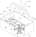
a dirt-cleaning separating electric mop cleaning tool, as shown in figure 1: the electric mop comprises an electric mop 1 and a mop bucket 2, wherein the electric mop comprises a mop rod 11 and a mop head 12, a wiping object 13 driven by a motor to rotate is arranged on the mop head, the mop bucket comprises a clean water area 21 and a sewage area 22 which are mutually independent, a washing component 3 for cleaning the wiping object is arranged in the clean water area, the clean water area can be lifted and has a high position and a low position, and the washing component can be lifted and lowered along with the clean water area;
when the clean water area is positioned at a low position, the clean water area can store water and the electric mop is placed in the clean water area for cleaning; after cleaning, the clean water is operated to move upwards to a high position, at the moment, the clean water area is communicated with the sewage area, water of sewage generated by cleaning in the clean water area can flow into the sewage area through the communicated channel, and at the moment, the electric mop can be dewatered in the clean water area.
The cleaning tool of the utility model stores the clear water in the clear water area before use, the sewage area is empty at the moment, the cleaning of the electric mop is carried out in the clear water area, after the cleaning is finished, the clear water area is operated to go up, when going up to a high position, the water in the clear water area flows to the lower sewage area under the action of gravity, at the moment, the clear water area is in an anhydrous state, and the electric mop can be dewatered in the dry area; when the cleaning is needed again, water is injected into the clean water area again, the water injection mode is various, for example, an external water tank, an external water pipe and a faucet are arranged, or manual water injection is carried out, and water injection control can be completed through automatic devices such as an electromagnetic valve;
in the embodiment, the clear water area and the sewage area are arranged in the horizontal direction, so that the height of the mop bucket can be reduced; the sewage area is arranged at one side of the clean water area or around the clean water area, so that the length, the width or the diameter of the mop bucket can be reduced while the water storage capacity is ensured, and the size of the mop bucket is reduced, so that the mop bucket can be used and stored more conveniently.
In addition, the dewatering mode is scraping and squeezing dewatering of the wiping objects and the washing and brushing part, the rotation of the wiping objects can also carry out centrifugal dewatering (spin-drying) while scraping and dewatering, and the two modes simultaneously act, so that the dewatering efficiency and the dewatering effect of the electric mop are improved.
The utility model discloses an electric mop is equipped with the drive the rotatory driving motor of wiper, its kind form is not limited, can be rotatory hair style flat mop, rotation type band mop and/or horizontal roller-type rotatory mop.
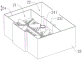
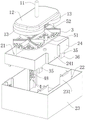
As shown in fig. 1 to 3: the mop bucket of this embodiment includes a first bucket body 23 and a second bucket body 24, the second bucket body can be accommodated in the first bucket body and can be lifted to the high position and lowered to the low position, the first bucket body constitutes the sewage area, and the second bucket body constitutes the clean water area.
When the sealing structure is implemented, a sealing element is arranged between the second barrel body and the first barrel body, and the sealing element can be any existing sealing structure, preferably a rubber strip sealing structure, and comprises a sealing strip, a foaming sealing structure or a sealing element with a metal framework.
The side wall of the second barrel body is provided with a water outlet 241, and a baffle 231 attached to the water outlet is arranged in the first barrel body;
when the second barrel body is positioned at a low position, the water outlet is closed after being shielded by the baffle, when the second barrel body is positioned at a high position, the water outlet is opened after being separated from the baffle, and the opened water outlet forms a channel communicated with the sewage area.
The water outlet can also be arranged as a through hole penetrating through the side wall of the second barrel body, and the through hole is close to the bottom of the second barrel body so as to facilitate the clean flowing of the sewage;
also in practice, a seal is provided between the water outlet and the baffle.
As shown in fig. 4 and 5: the brushing means includes at least one of a washing brush 32, a washing blade 33, or a washing roller 34;
the washing parts include any washing devices in the prior art such as a washing brush and a washing roller, as is well known, mop cleaning materials are various, such as a flat cloth mop, the plate-shaped or brush-shaped washing parts have good cleaning effect, such as multi-beam strip-shaped cleaning materials, and direct rotary washing in water is reasonable, such as a collodion mop (sponge and foam cotton), the washing brush or the washing roller can be used, therefore, the washing parts arranged on the washing disc have various combination modes, and the utility model discloses several typical modes have also been just enumerated.
In this embodiment, the brushing member further includes a cleaning disc 31, the cleaning brush, the cleaning scraper, or the cleaning roller are all fixedly disposed on the cleaning disc, the cleaning disc is fixedly disposed in the cleaning area, and of course, the brushing member may also be directly mounted in the clean water area.
The washing and brushing part of the utility model is fixedly connected, is in a fixed state when cleaning the mop, and implements cleaning operation by the rotation of the electric mop wiper;
of course, the scrubbing means may be actively rotatable, the rotating means being said cleaning disc and being rotated in a direction opposite to the direction of rotation of the electric mop wiper.
In addition, as shown in fig. 5: when there are a plurality of wipes, a plurality of cleaning disks corresponding to the wipes may be provided independently or may be combined to form an integral structure.
The wiping material of the electric mop of the utility model has at least two rotating speeds, wherein one of the rotating speeds is lower for the rotating speed during mopping and cleaning, the other rotating speed is higher for the rotating speed during dehydration, and the higher rotating speed can improve the dehydration effect;
three speeds can be set, and the three speeds respectively correspond to mopping, cleaning and dewatering, so that the effect of each function is better.
The way of realizing the lifting of the clear water area in this embodiment is shown in fig. 1: the clear water area is connected to a lifting device 4, by which the clear water area can be located at the high position or at the low position.
The connection mode of the clean water area and the lifting device can be a fixed connection mode, an integrally formed structure, a detachable connection mode and the like, preferably the detachable connection mode is adopted, the clean water area and the lifting device are relatively fixed when in use, and a washing component of the clean water area can also be detached for cleaning or replacement;
in this embodiment, the clean water area is formed by the second barrel body, and the second barrel body is fixedly installed on the lifting device.
A clamping structure 5 is arranged between the mop head and the clean water area, and the clean water area can be clamped and driven to ascend or descend by the clamping structure.
In the embodiment, the clamping structure is arranged between the electric mop and the brushing part, and the electric mop is contacted with the brushing part for cleaning and dewatering, so that the clamping structure matched with the electric mop and the brushing part is reasonable; certainly, a clamping structure can be arranged between the side wall of the clean water area (the second barrel body) and the electric mop, so that the electric mop can be clamped with the mop head, and the upward movement of the clean water area can be driven.
The clamping structure of this embodiment is shown in fig. 9 and 10: the positioning device comprises a positioning column 51 and a positioning hole 52 which are matched with each other, wherein a protrusion 521 which extends towards the inside of the positioning hole and has elasticity is arranged on the side wall of the positioning hole, and the positioning column can be clamped by the protrusion when inserted into the positioning hole.
Obviously, the positioning column and the positioning hole are respectively disposed in the electric mop and the clean water area, and the elastic protrusion may be a snap structure realized by elasticity of its own material, as shown in fig. 9: the protruding part is of an integral structure and has elasticity, and the clamped positioning column is provided with a flange 511 clamped with the protruding part;
it is also possible as shown in fig. 10: the protrusion is a movably mounted clamping head 5211, which is driven by an elastic member 5212 to extend into the positioning hole, thereby achieving elastic clamping.
Preferably, the positioning hole and the positioning column are arranged coaxially with the rotation axis of the wiper, and the coaxial axis refers to the rotation axis of the wiper when the electric mop is inserted for cleaning or dewatering.
The lifting device of the present embodiment is shown in fig. 6 to 8: the mop bucket comprises a fixed column 41, a moving tube 42 and a positioning rod 43, wherein the fixed column is fixedly connected to the mop bucket, the moving tube is sleeved outside the fixed column, the positioning rod passes through the moving tube and is inserted into an insertion hole in the center of the fixed column, the positioning rod and the fixed column are relatively stopped rotating, and the upper end of the positioning rod is a supporting part;
the moving pipe penetrates through the clean water area and is axially fixed with the clean water area so that the clean water area can lift along with the moving pipe, and the moving pipe penetrates to one end of the clean water area to form the positioning column;
the fixed column is sleeved with a transmission piece 44, the transmission piece is in spiral connection transmission with the moving pipe, the moving pipe can move up and down to drive the transmission piece to rotate, and a ratchet structure 441 capable of being meshed is arranged between the transmission piece and the moving pipe;
a rotation stopping structure 431 is arranged between the inner peripheral surface of the moving pipe and the positioning rod, and the positioning rod can move along the axial direction of the positioning rod, so that the rotation stopping structure can be engaged or disengaged; when the movable pipe is meshed with the fixed column, the movable pipe and the positioning rod are circumferentially stopped, and the positioning rod and the fixed column are circumferentially stopped, so that the movable pipe cannot rotate and cannot descend; when disengaged, the movable tube may be rotated down.
In detail, when the lifting device is in a normal state, the moving pipe and the positioning rod are both located at the low position, that is, the washing component is also located at the low position, and the electric mop is abutted against the positioning rod and is cleaned by the washing component;
when the dewatering operation is required after cleaning, the electric mop is lifted up, the movable pipe and the clean water area can be driven to move upwards through the clamping structure, the positioning rod is driven to move upwards in the continuous upward movement process, after the electric mop moves upwards to the terminal point, the electric mop can push the positioning rod to move downwards (manually or under the action of gravity) and enable the rotation stopping structure to be occluded, and the ratchet structure of the transmission part is also engaged at the moment, so that the movable pipe cannot rotate at the moment (the movable pipe and the transmission part can only rotate in a moving mode in a spiral connection mode, and the movable pipe can move up and down in a rotating mode), therefore, the movable pipe cannot move up and down, and the movable pipe (with the positioning rod and the clean water area) can be kept at a high position;
after the dewatering operation is finished, the electric mop is separated from the lifting device, at the moment, the moving pipe is not clamped by the mop head, and slightly falls by a distance (the falling distance is the distance for enabling the rotation stopping structure to be disengaged from the occlusion) to enable the rotation stopping structure to be disengaged, at the moment, the moving pipe can rotate and fall, and meanwhile, the brushing component also descends until the normal state is recovered.
The lifting device of the embodiment can realize coaxial lifting and positioning of the mop in the mop bucket, so that the mop can be cleaned at a low position, the mop is lifted to a position above the water level through the lifting mechanism after being cleaned to be dewatered, and the cleaning and dewatering are coaxially performed, so that the cleaning and dewatering water are combined into one and are coaxially performed, the structure is simplified, the operation is convenient and fast, the volume of the mop bucket can be reduced, the packaging, the transportation, the storage and the storage are convenient, and the use is more labor-saving; and the utility model discloses an its simple structure of elevating system easily makes and assembles, and is with low costs, does benefit to marketing.
The structure of the lifting device in this embodiment is disclosed in the chinese utility model patent application No. 201810014543.7.
Since the lifting devices of the present embodiment are axial supporting structures, the number of the lifting devices is preferably the same as the number of the wipers, and the lifting devices and the wipers are preferably coaxially disposed, so that a more stable supporting function can be provided;
of course, a single lifting device can be arranged, and the lifting device is positioned at the center of the mop head; or a plurality of lifting devices are arranged but are not coaxially arranged with the wiping object, and two lifting devices are symmetrically arranged; or a plurality of lifting devices are arranged and support the clean water area together;
the central position of the lifting device is provided with 1, the central position can ensure the horizontal balance of the mop head, and the lifting device 1 is beneficial to controlling the cost; 2 lifting devices are arranged to improve the balance of the mop head during cleaning and dewatering; of course, 3 are also provided, thereby further improving the balance.
Example 2:
the present embodiment is different from embodiment 1 in that the structure of the lifting device is as shown in fig. 11 to 13: the device comprises a fixed seat 45 and a lifting column 46, wherein the clean water area is fixedly connected or detachably connected with the lifting column;
the fixing base fixed connection in the mop bucket, the lift post with the fixing base is worn to overlap and is connected, just the lift post can be followed its axial slip and along its circumference rotation, the lateral wall of fixing base is equipped with high-order step 451, high-order step is followed the circumference equipartition of lateral wall, and is every adjacent still be equipped with low level step 452 between the high-order step, the lateral wall of lift post is equipped with and can arranges in high-order step or the locating piece 461 of low level step.
When the electric mop is placed in the clear water area, the lifting column can be driven to ascend by the aid of the clamping structure for clamping the lifting column, and positioning blocks on the lifting column are respectively arranged on the high-position step or the low-position step, so that the clear water area can be located in the low-position cleaning mode and the high-position dewatering mode.
In this embodiment, the lifting column penetrates through the fixing seat, the high-order step and the low-order step are disposed on the inner side wall of the fixing seat, and the positioning blocks are disposed on the outer side wall of the lifting column.
According to the lifting device, the cleaning and the dewatering are coaxially carried out, the cleaning and the dewatering are combined into one and are coaxially carried out, the structure is simplified, the operation is convenient, the size of the mop bucket can be reduced, the packaging, the transportation, the storage and the storage are convenient, and the labor is saved during the use; and the utility model discloses an its simple structure of elevating system easily makes and assembles, and is with low costs, does benefit to marketing.
In this embodiment, the lifting device is an axial lifting mechanism, and preferably, the lifting device and the wiper are coaxially arranged, and as a preferred embodiment, the lifting column and the positioning column are the same piece, that is, the upper end of the lifting column passes through the bottom surface of the clean water area and is fixedly or detachably connected with the bottom surface, and the end, through which the lifting column passes, constitutes the positioning column.
In this embodiment, in order to obtain the maximum lifting stroke in the end lifting device, the low support portion is eliminated, as shown in fig. 12 and 13: the lower steps are the bottom of the mop barrel, and a channel for the positioning block to slide is arranged between the adjacent high steps.
The lower step is cancelled, so that the lifting column directly descends to the bottom of the mop barrel to form a lower state, and the lower step part of the side wall of the fixing seat is a channel for the positioning block to slide through, thereby being beneficial to simplifying the structure of the fixing seat and reducing the preparation difficulty and cost.
It can be understood that the above structure is that the lifting column can be rotated by a certain angle through manual operation to realize the switching of the abutting state of the positioning block between the high-position step and the low-position step, and this embodiment also provides a mode without manual operation of the rotation angle as a best mode, as shown in fig. 12 and 13: the fixing seat is provided with a ratchet 453, the tooth end of the ratchet is arranged downwards, the upper surface of the positioning block is an inclined surface 4611, when the lifting column rises, the inclined surface is abutted to the ratchet and can drive the lifting column to rotate, and the positioning block can sequentially fall into the high-level step and the low-level step through the rising rotation of the lifting column at each time.
Of course, the inclined plane on the positioning block can also be independently arranged, that is, not arranged together with the positioning block, the inclined plane can also be arranged on the upper surface of the independently arranged protruding structure.
More specifically, the ratchets, the high-position steps and the low-position steps are arranged in a staggered manner, the positioning blocks are separated from the high-position steps or the low-position steps and move upwards to contact the inclined surface parts of the ratchets, and the shifting of the circumferential angles of the lifting column is completed through the inclined surfaces, and the high-position steps and the low-position steps are arranged at intervals, so that the positioning blocks can sequentially fall into the high-position steps and the low-position steps by the action of switching every time the lifting column moves upwards, and the electric mop is switched between the high-position steps and the low-position steps; the ratchet structure can be convenient to realize the sequential switching of the high position and the low position, is convenient and quick, does not need manual intervention operation, and greatly reduces the learning cost of a user.
This embodiment also provides another implementation, as shown in fig. 14: the lifting device and the wiping object are not coaxially arranged, but can be arranged;
as in embodiment 1, this embodiment also has a clamping structure, and the clamping structure of this embodiment is shown in fig. 15: the positioning device comprises a positioning column 51 and a positioning hole 52 which are matched with each other, wherein a protrusion 521 which extends towards the inside of the positioning hole and has elasticity is arranged on the side wall of the positioning hole, and the clamped positioning column is provided with a concave ring 511 which is clamped with the protrusion.
Example 3:
the present embodiment is different from embodiment 1 in the structure of the lifting device, as shown in fig. 16 and 17: the lifting device comprises an elastic component 471 arranged between the clean water area and the mop bucket, the elastic component acts on the clean water area and drives the clean water area to be positioned at the high position, and the elasticity of the elastic component can support the total weight of the electric mop when the electric mop is positioned in the clean water area;
when in use, the electric mop is pressed downwards to overcome the elasticity of the elastic part so that the clean water area and the electric mop are positioned at a low position for cleaning; after cleaning, the downward pressure is released, and under the action of the elastic component, the clean water area and the electric mop are positioned at high positions for dewatering.
According to the lifting device, the high-position dehydration of the electric mop is realized through the elastic component, and the electric mop and the clean water area are positioned at the high positions because the elasticity of the elastic component is greater than the dead weight of the electric mop and the clean water area when the electric mop is placed in the clean water area; when cleaning is needed, the mop rod is pressed downwards to overcome the elasticity of the elastic component, so that the wiping material and the clean water area of the mop head both move downwards to a low position, then water is injected into the clean water area, so that the wiping material is immersed into the water or partially immersed into the water, and the cleaning operation can be carried out, and the water injection mode is the same as that of the embodiment 1;
the lifting device in the embodiment has simple and clear lifting logic and very simple operation, has simple structure and fewer parts, reduces actual effect risk, has simple volume, is favorable for reducing the whole volume of the mop bucket, and is convenient for packaging, transportation, storage and storage.
The elasticity providing unit of the elastic member may be an elastic element such as a coil spring, a leaf spring, a torsion spring, etc., preferably a coil spring.
In this embodiment, the lifting device further includes a supporting column 47, the supporting column can move along an axial direction of the supporting column, the clean water area is fixedly connected or detachably connected to the supporting column, and the elastic member is located between the supporting column and the mop bucket.
More specifically, the supporting column is sleeved on a fixing seat 45, the supporting column can move along the axial direction of the supporting column, the fixing seat is fixedly connected to the mop bucket, the elastic component is arranged between the supporting column and the fixing seat or between the supporting column and the mop bucket, namely acting forces at two ends of the elastic component are respectively arranged between the supporting column and the mop bucket, and are used for driving the supporting column to move upwards, the upward movement stroke of the supporting column is limited by the fixing seat, and when the supporting column is in a normal state, a supporting part of the supporting column is located at an upward vertex of the supporting column under the action of the elastic component, namely, in a high state, so that the clean water area is also located in a high state;
in the embodiment, a clamping structure is not needed between the electric mop and the brushing component, which is well understood, the lifting device of the embodiment is normally located at a high position, and the operation of switching to the low position is to press the mop downwards, so that the clamping structure is not needed to drive the brushing component to move upwards;
however, in order to ensure that the electric mop has better stability when being placed in a clean water area for cleaning or dewatering, a positioning structure is arranged between the mop head and the scrubbing component, and comprises a positioning column 51 and a positioning hole 52 which are matched with each other; the positioning column is arranged on the mop head and the positioning hole is arranged on the washing component, or the positioning column is arranged on the washing component and the positioning hole is arranged on the mop head.
The lifting device of the present embodiment is also configured to lift axially, and the lifting device of the above embodiment is disposed coaxially with the wiper, and the positioning post and the positioning hole are also disposed coaxially, so that it is preferable to configure the positioning post and the supporting post as a same piece in this configuration. Namely as shown in fig. 16: the upper end of the supporting column penetrates through the clean water area and the washing component, the penetrating end of the supporting column forms a positioning column, and the mop head is provided with a positioning hole for the positioning column to insert.
This example also shows another embodiment, as shown in fig. 18: the lifting device and the wiper are arranged non-coaxially, and the corresponding positioning column changes positions along with the lifting device;
however, the positions of the lifting device and the positioning post are not necessarily the same (not necessarily coaxial), and they can be matched arbitrarily, which is also easy to understand and implement.
Example 4:
the present embodiment is different from embodiment 1 in the structure of the lifting device, as shown in fig. 19 and 20: the clean water area is movably connected with the mop bucket, the lifting device comprises a slide way 48 for limiting the movement track of the clean water area, the slide way is arranged on the mop bucket or the clean water area, the slide way is provided with a high-position supporting part 481 and a low-position supporting part 482, the clean water area can move to the high-position supporting part or the low-position supporting part along the track of the slide way, and the slide way is also provided with a blocking part 483 for switching the falling position of the clean water area;
when the device is used, the clear water area is positioned on the low-position supporting part or the high-position supporting part, when the clear water area moves upwards, the clear water area can block the upward movement through the blocking part, and the downward movement direction of the clear water area can be switched through the blocking part.
The complete cleaning and dewatering process comprises the following steps: the clean water area is positioned on the low-position supporting part to clean the electric mop, the clean water area is driven to move upwards through the clamping structure after being cleaned, the upward movement is stopped through the blocking of the blocking part, the clean water area can be guided to fall into the high-position supporting part along the slide way, and the electric mop is operated to dewater when being positioned on the high-position supporting part;
the high-order and low-order switching is realized through the passageway of restriction movement track, and the track can set up the lateral wall at the mop bucket, and the structure of slide is also comparatively retrencied, need not the lift that many parts cooperation realized electronic mop, reduce cost.
The slide of this embodiment is shown in fig. 20: the high-position support part comprises an upper channel 485 and a lower channel 486 which are respectively positioned at two sides of the high-position support part, the blocking part is positioned above the high-position support part and comprises a first blocking part 4831 and a second blocking part 4832, and the low-position support part is positioned at the outlet position of the lower channel;
the clear water area stops when ascending to the first blocking part on the ascending channel and descends and falls back to the high-level supporting part under the guidance of the first blocking part; and the lower supporting part is arranged at the lower part of the lower supporting part, and the lower supporting part is arranged at the lower part of the lower supporting part.
The setting mode of slide includes:
(1) the slide way is located on the side wall of the mop bucket, the side wall of the clean water area is provided with a slide column 35 which can be contained in the slide way to slide, as shown in fig. 19: the slideway is arranged on the side wall of the mop bucket;
(2) the slide way is located on the side wall of the clean water area, the side wall of the mop bucket is provided with a slide column 35 which can be contained in the slide way to slide, as shown in fig. 22: the clean water area of the slide way has the same structure principle as that of the above-mentioned embodiment, but the directions of the slide way and the high-level supporting part and the low-level supporting part are opposite, because the moving directions of the washing component and the mop bucket are opposite, so the directions of the slide way and the mop bucket are opposite.
In this embodiment, the first blocking part and the second blocking part are adjacently arranged and both have inclined guide surfaces, and the tail end of the guide surface of the first blocking part is located above the high-position supporting part or is deviated to the upper part of the high-position supporting part, so that the clean water area can be guided to fall into the high-position supporting part when moving downwards; the tail end of the guide surface of the second blocking part is positioned at the inlet of the lower channel, and can guide the clear water area to fall into the lower channel when the clear water area descends, and then the motion track of the clear water area is limited by the lower channel, so that the clear water area falls into the lower supporting part; and sequentially switching between the high position and the low position in a circulating mode.
In the embodiment, in order to simplify the structure of the slide way and reduce the overall height of the slide way, the lower support part of the body is cancelled, namely the lower support part is the bottom of the mop bucket, the lower support part is cancelled when the washing brush falls into the bottom of the mop bucket, and the washing brush directly falls to the bottom of the mop bucket, so that the structure of the slide way is simplified, the service life of the lifting device is prolonged, and the manufacturing cost of the cleaning tool can be controlled.
In this embodiment, the brushing means further has a pad 36, when the brushing means is located at the low position, the pad is supported on the bottom of the mop bucket, the horizontal height of the low position is set by the height of the pad, and in this embodiment, the sliding column 35 is disposed on the sidewall of the pad.
Example 5:
the present embodiment is also different from embodiment 4 in the structure of the chute, as shown in fig. 23 to 26: the slideway is arranged on a swing frame 49 which is rotatably connected with a box body 491, the swing frame is provided with an elastic piece 492 driving the swing frame to deflect towards one side, the box body is provided with a vertically arranged guide groove 4911, and the slideway can be exposed from the guide groove part.
In this embodiment, the swing frame, the box body and the elastic member are all mounted by being sleeved on the pin 493, the box body is fixedly connected to the mop bucket, two ends of the elastic member respectively act on the box body and the swing frame to enable the swing frame to deflect towards one side, and the box body limits the deflection angle of the swing frame, so that the swing frame can rotate back and forth within a certain angle range, and is fixedly deflected towards one side in a normal state when no external force exists;
through the combination of guide way 4911 and slide 48, the restriction the orbit of clear water district makes it can get into in proper order under the effect of blocking part high-order supporting part or low level supporting part, and the rethread the effect of elastic component realizes going upward once more after breaking away from high-order supporting part and can get into again the slide realizes the circulation switching of high low position.
The structure of the lifting device used in this embodiment is disclosed in chinese utility model patent application No. 201510518015.1.
The above only is the embodiment of the present invention, not limiting the scope of the present invention, all the equivalent structure changes made in the specification and the attached drawings or directly or indirectly applied to other related technical fields are included in the same principle as the present invention.
Claims (23)
1. The utility model provides a clean dirty separation electric mop burnisher, includes electric mop (1) and mop bucket (2), electric mop includes mop pole (11) and mop head (12), be equipped with on the mop head by the rotatory wiping thing (13) of motor drive, its characterized in that: the mop bucket comprises a clean water area (21) and a sewage area (22) which are mutually independent, a brushing component (3) for cleaning the wiping objects is arranged in the clean water area, the clean water area can be lifted and has a high position and a low position, and the brushing component can be lifted and lowered along with the clean water area;
when the clean water area is positioned at a low position, the electric mop can be cleaned in the clean water area; when the clear water district is located the high position, the water in the clear water district flows into through the intercommunication passageway the sewage district, electronic mop in clear water district can accomplish the dehydration.
2. The dirt separation electric mop cleaning tool of claim 1, wherein: the mop bucket comprises a first bucket body (23) and a second bucket body (24), the second bucket body can be contained in the first bucket body and can be lifted to the high position and lowered to the low position, the first bucket body forms the sewage area, and the second bucket body forms the clean water area.
3. The dirt separation electric mop cleaning tool of claim 2, wherein: a water outlet (241) is formed in the side wall of the second barrel body, and a baffle (231) attached to the water outlet is formed in the first barrel body;
when the second barrel body is positioned at a low position, the water outlet is closed after being shielded by the baffle, when the second barrel body is positioned at a high position, the water outlet is opened after being separated from the baffle, and the opened water outlet forms a channel communicated with the sewage area.
4. The dirt separation electric mop cleaning tool of claim 1, 2 or 3, wherein: the clear water area is connected to a lifting device (4), by means of which the clear water area can be located at the high position or at the low position.
5. The dirt separation electric mop cleaning tool of claim 4, wherein: a clamping structure (5) is arranged between the mop head and the clean water area, and the clean water area can be clamped and driven to ascend or descend by the clamping structure.
6. The dirt separation electric mop cleaning tool of claim 5, wherein: the clamping structure comprises a positioning column (51) and a positioning hole (52) which are matched with each other, wherein a protrusion (521) which extends towards the inside of the positioning hole and has elasticity is arranged on the side wall of the positioning hole, and the positioning column can be clamped by the protrusion when inserted into the positioning hole.
7. The dirt separation electric mop cleaning tool of claim 6, wherein: the positioning hole and the positioning column are coaxially arranged with the rotation axis of the wiping object.
8. The dirt separation electric mop cleaning tool of claim 5, 6 or 7, wherein: the lifting device comprises a fixed seat (45) and a lifting column (46), and the clean water area is fixedly connected or detachably connected with the lifting column;
fixing base fixed connection in the mop bucket, the lift post with the fixing base is worn the cover to be connected, just the lift post can be followed its axial slip and along its circumference rotation, the lateral wall of fixing base is equipped with high-order step (451), high-order step is followed the circumference equipartition of lateral wall, and is every adjacent still be equipped with low level step (452) between the high-order step, the lateral wall of lift post is equipped with and can arranges in high-order step or the locating piece (461) of low level step.
9. The dirt separation electric mop cleaning tool of claim 8, wherein: the upper end of the lifting column penetrates through the bottom surface of the clean water area, the clean water area can lift along with the lifting column, and the clamping structure is arranged between one end, penetrating out of the lifting column, of the lifting column and the mop head.
10. The dirt separation electric mop cleaning tool of claim 8, wherein: the lower steps are the bottom of the mop barrel, and a channel for the positioning block to slide is arranged between the adjacent high steps.
11. The dirt separation electric mop cleaning tool of claim 8, wherein: the fixing seat is provided with a ratchet (453), the tooth end of the ratchet is arranged downwards, the upper surface of the positioning block is an inclined surface, when the lifting column rises, the inclined surface is abutted to the ratchet and can drive the lifting column to rotate, and the positioning block can sequentially fall into the high-level step and the low-level step through the rising rotation of the lifting column at each time.
12. The dirt separation electric mop cleaning tool of claim 4, wherein: the lifting device comprises an elastic component (471) arranged between the clean water area and the mop bucket, the elastic component acts on the clean water area and drives the clean water area to be positioned at the high position, and the elasticity of the elastic component can support the total weight of the electric mop when the electric mop is placed in the clean water area;
when in use, the electric mop is pressed downwards to overcome the elasticity of the elastic part so that the clean water area and the electric mop are positioned at a low position for cleaning; after cleaning, the downward pressure is released, and under the action of the elastic component, the clean water area and the electric mop are positioned at high positions for dewatering.
13. The dirt separation electric mop cleaning tool of claim 12, wherein: the lifting device comprises a supporting column (47), the supporting column can move along the axial direction of the supporting column, the clean water area is fixedly connected or detachably connected with the supporting column, and the elastic component is positioned between the supporting column and the mop bucket.
14. The dirt separation electric mop cleaning tool of claim 12, wherein: a positioning structure is arranged between the mop head and the washing component, and the positioning structure comprises a positioning column (51) and a positioning hole (52) which are matched with each other;
the positioning column is arranged on the mop head and the positioning hole is arranged on the washing component, or the positioning column is arranged on the washing component and the positioning hole is arranged on the mop head.
15. The dirt separation electric mop cleaning tool of claim 13, wherein: the upper end of the supporting column penetrates through the clean water area and the washing component, the penetrating end of the supporting column forms a positioning column, and the mop head is provided with a positioning hole for the positioning column to insert.
16. The dirt separation electric mop cleaning tool of claim 5, 6 or 7, wherein: the clean water area is movably connected with the mop bucket, the lifting device comprises a slide way (48) for limiting the movement track of the clean water area, the slide way is arranged on the mop bucket or the clean water area, the slide way is provided with a high-position supporting part (481) and a low-position supporting part (482), the clean water area can move to the high-position supporting part or the low-position supporting part along the track of the slide way, and the slide way is also provided with a blocking part (483) for switching the falling position of the clean water area;
when the device is used, the clear water area is positioned on the low-position supporting part or the high-position supporting part, when the clear water area moves upwards, the clear water area can block the upward movement through the blocking part, and the downward movement direction of the clear water area can be switched through the blocking part.
17. The dirt separation electric mop cleaning tool of claim 16, wherein: the slideway comprises an upper slideway (485) and a lower slideway (486) which are respectively positioned at two sides of the high-position supporting part, the blocking part is positioned above the high-position supporting part, the blocking part comprises a first blocking part (4831) and a second blocking part (4832), and the low-position supporting part is positioned at an outlet position of the lower slideway;
the clear water area stops when ascending to the first blocking part on the ascending channel and descends and falls back to the high-level supporting part under the guidance of the first blocking part; and the lower supporting part is arranged at the lower part of the lower supporting part, and the lower supporting part is arranged at the lower part of the lower supporting part.
18. The dirt separation electric mop cleaning tool of claim 16, wherein: the low-position supporting part is the barrel bottom of the mop barrel, and the washing component is positioned at the low position when falling into the barrel bottom of the mop barrel.
19. The dirt separation electric mop cleaning tool of claim 16, wherein: the slideway is positioned on the side wall of the mop bucket, and the side wall of the clean water area is provided with a sliding column (35) which can be contained in the slideway to slide;
or the slide way is positioned on the side wall of the clean water area, and the side wall of the mop bucket is provided with a slide column (35) which can be contained in the slide way to slide.
20. The dirt separation electric mop cleaning tool of claim 17 or 18, wherein: the slideway is positioned on the side wall of the mop bucket, and the side wall of the clean water area is provided with a sliding column (35) which can be contained in the slideway to slide;
or the slide way is positioned on the side wall of the clean water area, and the side wall of the mop bucket is provided with a slide column (35) which can be contained in the slide way to slide.
21. The dirt separation electric mop cleaning tool of claim 4, wherein: 1 lifting device is arranged, and the 1 lifting device is positioned at the central position of the mop head when the electric mop is inserted into the mop for cleaning;
or the lifting devices are provided with a plurality of lifting devices which support the clean water area together.
22. The dirt separation electric mop cleaning tool of claim 1, wherein: the brushing means includes at least one of a washing brush (32), a washing blade (33), or a washing roller (34).
23. The dirt separation electric mop cleaning tool of claim 1, wherein: the mops of the power mop have at least two rotational speeds.
Priority Applications (1)
| Application Number | Priority Date | Filing Date | Title |
|---|---|---|---|
| CN202020334250.XU CN212630679U (en) | 2020-03-17 | 2020-03-17 | Dirt-cleaning separating electric mop cleaning tool |
Applications Claiming Priority (1)
| Application Number | Priority Date | Filing Date | Title |
|---|---|---|---|
| CN202020334250.XU CN212630679U (en) | 2020-03-17 | 2020-03-17 | Dirt-cleaning separating electric mop cleaning tool |
Publications (1)
| Publication Number | Publication Date |
|---|---|
| CN212630679U true CN212630679U (en) | 2021-03-02 |
Family
ID=74768302
Family Applications (1)
| Application Number | Title | Priority Date | Filing Date |
|---|---|---|---|
| CN202020334250.XU Expired - Fee Related CN212630679U (en) | 2020-03-17 | 2020-03-17 | Dirt-cleaning separating electric mop cleaning tool |
Country Status (1)
| Country | Link |
|---|---|
| CN (1) | CN212630679U (en) |
-
2020
- 2020-03-17 CN CN202020334250.XU patent/CN212630679U/en not_active Expired - Fee Related
Similar Documents
| Publication | Publication Date | Title |
|---|---|---|
| CN111248823A (en) | Dirt-cleaning separating electric mop cleaning tool | |
| CN111214190A (en) | Washing type dirt-removing separating electric mop cleaning tool | |
| CN108852212B (en) | Water-saving mop bucket | |
| CN107049189B (en) | Water-saving mop bucket | |
| CN111195111A (en) | Rotary dewatering cleaning tool for electric mop | |
| EP3841945B1 (en) | Water discharge control structure of washing bucket capable of separating clean water from dirty water for washing cleaning tool | |
| CN214048712U (en) | Flat mop cleaning bucket | |
| CN111227736A (en) | Electric mop cleaning tool | |
| CN212630679U (en) | Dirt-cleaning separating electric mop cleaning tool | |
| CN211933945U (en) | Washing type dirt-removing separating electric mop cleaning tool | |
| CN211834258U (en) | Rotary dewatering cleaning tool for electric mop | |
| CN214511070U (en) | Cleaning device for flat mop | |
| CN110664334A (en) | Cleaning tool | |
| CN211834256U (en) | Electric mop cleaning tool | |
| CN112493953A (en) | Cleaning tool with spin dryer tube | |
| CN211355272U (en) | Cleaning tool | |
| CN216535207U (en) | Flat mop cleaning barrel capable of efficiently cleaning dirt | |
| CN217338477U (en) | Cleaning tool | |
| CN212879165U (en) | Cleaning equipment for electric mop, electric mop and cleaning system | |
| CN210931246U (en) | Flat mop cleaning tool without lifting | |
| CN216495172U (en) | Mop bucket | |
| CN214595776U (en) | Cleaning tool | |
| CN211484431U (en) | Mop cleaning tool | |
| CN210408303U (en) | Flat mop cleaning tool with in-situ cleaning and spin-drying functions | |
| CN216090366U (en) | Mop cleaning tool capable of cleaning and separating dirt |
Legal Events
| Date | Code | Title | Description |
|---|---|---|---|
| GR01 | Patent grant | ||
| GR01 | Patent grant | ||
| CF01 | Termination of patent right due to non-payment of annual fee |
Granted publication date: 20210302 |
|
| CF01 | Termination of patent right due to non-payment of annual fee |