Therefore, the objective of the invention is to, provide a kind of certain hour needn't be placed and the installation method of the action button that undesirable element is few, reliability is high by the fixing mechanism afterwards of action button.
To achieve these goals, the method for fastening operating button of the present invention's the 1st scheme is that action button with thermoplastic resin system is installed in the installation method on the action bars that plate makes, and it is characterized in that:
On action bars, form drop-proof hole and stop protuberance;
On action button, setting is formed with the installation portion with a pair of I-shaped groove of the both sides of the edge sliding gomphosis of action bars, and on installation portion, form the pressurized portion overlapping and relative, and form the only fastener on the stop protuberance of card with drop-proof hole with a side of action bars;
At the installation portion of action button and action bars is chimeric, the fastener card ends under the state on the stop protuberance, the another side of action bars is supported on the limit with supporting station, the limit with pressurizing tool towards a side of action bars to pressurized pressurization, form and give prominence to the protuberance that the anti-avulsion in drop-proof hole is used.
The method for fastening operating button of the present invention's the 2nd scheme be on the basis of the 1st scheme further, make that pressurizing tool is a columned metallic salient angle (horm), its top is roughly hemisphere.
The method for fastening operating button of the present invention's the 3rd scheme is on the basis of the 1st or the 2nd scheme, further make the anti-avulsion edge part of the pressing position of the pressurized relatively portion of pressurizing tool, and pressurizing tool is applied in the dither of small amplitude when pressurization near the action bars drop-proof hole.
The method for fastening operating button of the present invention's the 4th scheme, be further on the basis of scheme 1,2 or 3, when the pressurized parts that pressurize with pressurizing tool, with button press instrument pressing operation button, so that pressurized of the action button upper side crimping with action bars, and the fastener of action bars and the crimping of stop protuberance.
The method for fastening operating button of the present invention's the 5th scheme, be on the basis of scheme 1,2,3 or 4 further, the stop protuberance of action bars forms from cutting to dig to a side of action bars with the edge part of the anti-avulsion edge part opposition side of drop-proof hole, the stop projection of supporting station in drop-proof hole of supporting action bars has raised line, and the protuberance of the action button that is processed into by pressurizing tool of pressurized portion is formed between anti-avulsion edge part and the raised line.
The method for fastening operating button of the present invention's the 6th scheme, be in scheme 1-5 on each the basis further, order is added in vibration frequency on the pressurizing tool for below 20KHz, amplitude is below 15 μ m.
The method for fastening operating button of the present invention's the 7th scheme, be in scheme 1-6 on each the basis further, when pressurized of pressurizing tool pressurization, not forcibly to establish block at its compression aspect, but with moulding pressure of setting and the overhang that limits protuberance pressing time.
The present invention has following effect.
The method for fastening operating button of the 1st scheme according to the present invention, end on the stop protuberance at action bars and tabling until the fastener card of action button in the slippage of action bars both sides of the edge because be the groove that makes action button earlier, use the pressurized portion of pressurizing tool pressurized heat moldable resin system then, so that protuberance protrudes in the drop-proof hole of action bars, so, can be installed on the action bars action button is instantaneous.Therefore compare with conventional case, because of not using bonding agent, so needn't in action button placement mechanism afterwards be installed for the curing of bonding agent, also the action that causes of adhesive-free is bad, can obtain the high stabilized quality of reliability, and can enhance productivity.
The method for fastening operating button of the 2nd scheme according to the present invention because be on the basis of scheme 1 further, make that pressurizing tool is columned metallic salient angle, its top is roughly hemispherical, so except the effect of scheme 1, the pressurizing tool after the pressurization is also extracted easily.
The method for fastening operating button of the 3rd scheme according to the present invention, because be further on the basis of scheme 1 or 2, make the anti-avulsion edge part of pressurizing tool to the close action bars drop-proof hole of pressing position of pressurized portion, and pressurizing tool is applied in the dither of small amplitude when pressurization, so, except the effect of scheme 1,2, can also make protuberance outstanding from pressurized easily by dither, and outstanding more, so can prevent action button loosening after fixing effectively at the anti-avulsion edge part of drop-proof hole.
Method for fastening operating button according to the present invention program 4, because be in scheme 1, further on 2 or 3 the basis, when pressurization part being pressurizeed with pressurizing tool, utilize button press instrument crimping operation button, so that pressurized of action button upper side crimping with action bars, and the fastener that makes action bars compresses the stop protuberance, so, except scheme 1, outside 2 or 3 the effect, when pressurizing tool pressurizes, can also make action button definitely positioning and fixing on action bars, especially, even apply dither to pressurizing tool, the deviating from of action button in the time of also preventing to pressurize, and prevent the loosening of fixing back action bars.
Method for fastening operating button according to the present invention program 5, because be in scheme 1,2, on 3 or 4 the basis further, the stop protuberance of action bars forms from cutting to dig to a side of action bars with the edge part of the stop edge portion opposition side of stop hole, the stop projection of supporting station in stop hole of supporting action bars has raised line, and the protuberance of the action button that is formed by pressurizing tool of pressurized portion is formed between anti-avulsion edge part and raised line, so, except scheme 1,2, outside 3 or 4 the effect, drop-proof hole can be bigger, the incision of stop protuberance is dug easily, and can be definitely forms protuberance at the anti-avulsion edge part of drop-proof hole because of raised line.
Method for fastening operating button according to the present invention program 6, the thermoplastic resin of pressurized portion can not become the state that dissolves completely, promptly do not stretch out resin thorn (hereinafter referred to as burr), can form protuberance at compression aspect effectively to the opposite direction fusion of the machine direction of pressurizing tool.
According to the present invention program 7 method for fastening operating button, though action bars deform or the situation of pressurized variable thickness under, as long as make the actuating pressure of pressurizing tool and time certain, the protrusion amount of protuberance that just can make formation is for certain substantially.
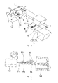
Describe an embodiment of method for fastening operating button of the present invention in detail referring now to Fig. 1 to Fig. 4.Fig. 1 is the main cutaway view that just action button has been installed in the state on the action bars, and Fig. 2 is its partial enlarged drawing, and Fig. 3 is a stereogram, and Fig. 4 is its partial enlarged drawing.
In Fig. 1 and Fig. 3, the 1st, the action bars of the mechanism 2 of operation boxlike phonograph etc. is made by the plate that is provided with drop-proof hole 3 and stop protuberance 4,5.Stop protuberance 4 is in a side opposite with the anti-avulsion edge part 3a of drop-proof hole 3, cuts from a side of action bars 1 to dig and integrally formed on action bars 1.Stop protuberance 5 is to the opposite direction bending of stop protuberance 4 and form with the narrow on action bars 1 top.The 10th, the location hole of action bars 1.In addition, in the mechanism 2 of boxlike phonograph, the 24th, motor, the 25th, flywheel, the 26th, base plate, the 27th, mounting flange.
The 6th, the action button of thermoplastic resin system, be formed with a pair of I-shaped groove 7 on its installation portion 13 with the both sides of the edge sliding gomphosis of action bars 1, on installation portion 13, also be formed with overlapping with a side of action bars 1 and relative pressurized 8, and card ends the fastener 11,12 on stop protuberance 4,5 with anti-avulsion machine 3.In the present embodiment, action button 6 has bar-shaped installation portion 13 and operation knob portion 14, installation portion 13 is made and the chimeric square tube shape of action bars 1 energy, thereby at the both sides of the edge chimeric a pair of I-shaped groove 7 of both sides formation with action bars 1, and offer in the bottom of top ends and to allow cutting that stop protuberance 5 interts meet 21, be provided with the otch 20 chimeric with stop protuberance 4 on the top of top ends.Fastener 11,12 is formed by the marginal portion of otch 20 and joint-cutting 21.In addition, in the both sides of joint-cutting 21, in order to support action bars 1, also be provided with the rise part 32 that protrudes upward.
The method for fastening operating button of this embodiment, to be about to the method that action button 6 is installed on the action bars 1 as follows: block respectively under the state only with stop protuberance 4,5 at the installation portion 13 of action button and action bars is 1 chimeric, fastener 11,12, another side with supporting station 15 supporting action bars 1, anti-avulsion that formation to drop-proof hole 3 in give prominence to protuberance 17 pressurize towards a side of action bars 1 to pressurized 8 with pressurizing tool 16 simultaneously.
In the case, being provided with the pin on supporting station 15 is the positioning convex 18 of embodiment, and this positioning convex 18 is chimeric with the location hole 10 of action bars 1, and action bars 1 is positioned on the supporting station 15.
Again, the also outstanding raised line 22 that is provided with on supporting station 15, under the chimeric state of the installation portion 13 of action button 6 and action bars 1, this raised line 22 is positioned at stop protuberance 4 sides of drop-proof hole 3, its width is narrower than the width of drop-proof hole 3, and protuberance 17 is formed between anti-avulsion edge part 3a and the raised line 22.
Have again, when pressurizeing with 16 pairs pressurized 8 of pressurizing tool, with button press instrument 23 crimping operation buttons 6, make pressurized 8 of action button 6 with action bars 1 crimping, and with fastener 11,12 by being pressed on the stop protuberance 4,5.
In addition, pressurizing tool 16 is cylindric metal salient angles, and its top 30 is roughly hemisphere.In the present embodiment, corresponding with the quantity of the action button 6 of installing simultaneously, this pressurizing tool 16 is provided with a plurality of on body 28 side by side.In addition, make pressurizing tool 16 towards pressurized 8 pressing position anti-avulsion edge 3a near the drop-proof hole 3 of action bars 1, and when pressurization, pressurizing tool 16 is applied the dither of small amplitude.
Below specify the installation order of this embodiment action button.At first mechanism 2 is arranged on the supporting station 15.At this moment, action bars 1 and supporting station 15 butts, the location hole 10 of action bars 1 is positioned the positioning convex 18 of supporting station 15 simultaneously.Then make the groove 7 of installation portion 13 of action button 6 chimeric with action bars 1, and be inserted into always make its fastener 11,12 abut on the stop protuberance 4,5 till, with button press instrument 23 bulldozing operation buttons 6.Under this state, from the top of the position relative, as 16 pairs pressurized 8 compressing of pressurizeing of pressurizing tool of dither with the drop-proof hole 3 of action bars 1.Like this, pressurized 8 resin is pushed in the space between the anti-avulsion edge part 3a of raised line 22 and drop-proof hole 3, forms protuberance 17.Why the top 30 of pressurizing tool 16 being made roughly hemispherically here, is for after forming protuberance 17, in pressurizing tool 16 can not be snapped and stay in pressurized 8 and can easily extract upward.And button press instrument 23 is in order to prevent that action button 6 from deviating from because of the influence of the pressurizing tool 16 of dither, and eliminate action button 6 in fixing back loosening in the glide direction of action bars 1.
According to present embodiment, because be the groove 7 of action button 6 is slided in the both sides of the edge of action bars 1, end on the stop protuberance 4,5 at action bars 1 and tabling until fastener 11,12 card of action button 6, then, pressurized 8 with 16 pairs of thermoplastic resin systems of pressurizing tool is pressurizeed, protuberance 17 is protruded in the drop-proof hole 3 of action bars 1, can action button 6 be installed on the action bars 1 in moment.Therefore, compare, because of using bonding agent with conventional case, place certain hour for the curing of bonding agent so needn't the back be installed in action button, and the action that adhesive-free causes is bad, can obtain high reliability and stabilized quality, and can enhance productivity.
In addition because pressurizing tool 16 is columniform metal horn shape punch, very top 30 be roughly hemispherical, so pressurization back pressurizing tool 16 is extracted easily.
In addition, because make pressurizing tool 16 towards pressurized 8 pressing position anti-avulsion edge part 3a near the drop-proof hole 3 of action bars 1, and pressurizing tool 16 has been applied in the dither of little amplitude when pressurization, because dither, protuberance 17 is outwards outstanding from pressurized 8 easily, simultaneously because of outstanding more, so can prevent reliably that action button 6 fixing backs are loosening at the anti-avulsion edge part 3a place of drop-proof hole 3 protuberance 17.
Have again, when with pressurized 8 of pressurizing tool 16 pressurization, because with button press instrument 23 bulldozing operation buttons 6, so that pressurized 8 and the upper side crimping of action bars 1 of action button 6, and the fastener 11,12 that makes action bars 1 respectively with 4,5 crimping of stop protuberance, so when pressurizing tool pressurizes, can locate and be fixed on action button 6 on the action bars 1 reliably, especially, even apply dither to pressurizing tool 16, the deviating from of action button 6 in the time of also preventing to pressurize, and can prevent the loosening of fixing back action bars 1.
In addition, because the stop protuberance 4 of action bars 1 cuts to dig to a side of action bars 1 from the edge part with the anti-avulsion edge part 3a opposition side of drop-proof hole 3 and forms, stop protuberance 4 sides of supporting station 15 in drop-proof hole 3 of supporting action bars 1 have raised line 22, the protuberance 17 of the action button 6 that is formed by pressurized 8 pressurizing tool 16 is formed between anti-avulsion edge part 3a and the raised line 22, so, drop-proof hole 3 can be bigger, stop protuberance 4 cuts easily and digs, and because raised line 22 can form protuberance 17 at the anti-avulsion edge part 3a place of drop-proof hole 3 definitely.
Again, in the present embodiment, be on action bars 1, to establish location hole 10, on supporting station 15, set position projection 18, but also can on action bars 1, establish projection, on supporting station 15, establish with protruding chimeric recess and make action bars 1 location.In addition, stop protrusion 4,5 only establishes that one of them is good, and again, it is good that the stop protuberance is located at the side margins of action bars 1.
In addition, be that 20KHz is following, amplitude is that then the thermoplastic resin of pressurized portion becomes the semi-molten state below the 15 μ m if put on the vibration frequency of pressurizing tool, can form protuberance effectively at the compression aspect of pressurizing tool.
In addition, when pressurizing tool 16 to pressurized 8 when pressurization, if at its compression aspect mandatory block is not set, and with moulding pressure of setting and the protrusion amount that limits protuberance pressing time, then the size of the protuberance that is determined by pressure of setting and time can keep certain.
The operation knob installation method of the 1st scheme according to the present invention, because be the groove of action button is slided in the both sides of the edge of action bars, end on the stop protuberance at action bars and tabling until the fastener card of action button, then with pressurized the pressurization of heating tool to thermoplastic resin system, protuberance is given prominence in the drop-proof hole of action bars, so, can action button be installed on the action bars in moment.Compare with conventional example, because do not use bonding agent, so needn't in action button the back be installed processing is placed by mechanism for the curing of bonding agent, it is bad also not have the action that causes because of bonding agent, can obtain high reliability and stabilized quality, and can enhance productivity.
The method for fastening operating button of the 2nd scheme according to the present invention, because be on the basis of the 1st scheme, make further that pressurizing tool is columned metal horn shape punch, its top is for roughly hemispherical, so except the effect of scheme 1, the pressurizing tool after the pressurization is extracted easily.
The method for fastening operating button of the 3rd scheme according to the present invention, because be on the basis of scheme 1 or scheme 2, further make the anti-avulsion edge part of pressurizing tool to the drop-proof hole of the close action bars of pressing position of pressurized portion, and pressurizing tool has been applied in the dither of little amplitude when pressurization, so except the effect of scheme 1 or scheme 2, can also make protuberance easy by dither from the outstanding transfiguration of pressurized portion, and make protuberance give prominence to anti-avulsion edge part morely, therefore can prevent action button loosening after fixing reliably at drop-proof hole.
The method for fastening operating button of the 4th scheme according to the present invention, because be in scheme 1, on 2 or 3 the basis, when with pressurized of pressurizing tool pressurization, further push down action button with the button press instrument, so that pressurized of action button upper side crimping with action bars, and the fastener that makes action bars is by being pressed on the stop protuberance, so, except scheme 1, outside 2 or 3 the effect, when pressurizing tool pressurizes, can also with action button reliably positioning and fixing on action bars, especially, even pressurizing tool is applied dither, the deviating from of action button in the time of also preventing to pressurize, and can prevent the loosening of fixing back action bars.
The method for fastening operating button of the 5th scheme according to the present invention, because be in scheme 1,2, on 3 or 4 the basis further, the stop protuberance of action bars forms from cutting to dig to a side of action bars with the edge part of the anti-avulsion edge part opposition side of drop-proof hole, the supporting station of supporting action bars has raised line at the stop projection of drop-proof hole, the protuberance of the action button that is processed by pressurizing tool of pressurized portion is formed between anti-avulsion edge part and the raised line, so, except scheme 1,2, outside 3 or 4 the effect, drop-proof hole can be bigger, the incision of stop protuberance is dug can be easy, and, can form protuberance at the anti-avulsion edge part place of drop-proof hole reliably by raised line.
The method for fastening operating button of the 6th scheme according to the present invention does not have " burr " that produce with the thermoplastic resin of the compression aspect fusion on the contrary of pressurizing tool, and can form protuberance effectively at compression aspect.
The method for fastening operating button of the 6th scheme according to the present invention, though action bars deform or the situation of pressurized variable thickness under, it is certain that the overhang of the protuberance of formation also can keep substantially.