Combined seismic source excitation method and system for enhancing seismic illumination
Technical Field
The invention relates to the field of exploration earthquakes, in particular to a combined seismic source excitation method and system for enhancing seismic illumination.
Background
The seismic illumination calculation can be used for the design optimization of an observation system for seismic acquisition, the amplitude compensation of underground complex geologic body structure imaging and the like. Generally, the seismic illumination is calculated by accumulating the energy of seismic wave field excited by seismic source, and for complex subsurface structure areas, the energy of seismic wave propagated in the underground, i.e. the subsurface illumination, is not uniform, that is, there may be some subsurface areas with low illumination, which is not favorable for seismic wave detection in these areas, and this is especially easy to happen in the high and steep geological structures in the underground. The combined seismic source can enhance the excitation energy of seismic waves through the interference of seismic wave fields, and is therefore a way to enhance the seismic illumination of underground structures.
Disclosure of Invention
The invention aims to provide a combined seismic source excitation method and a combined seismic source excitation system for enhancing seismic illumination, which can enhance the coherence of a seismic wave field along a propagation spherical surface by changing the position of a combined seismic source, and achieve the purpose of enhancing the seismic illumination intensity by a plurality of combined seismic sources.
In order to achieve the purpose, the invention provides the following scheme:
a combined source firing method to enhance seismic illumination, comprising:
determining a combined source comprising n sub-sources;
setting an excitation spherical wave, distributing sub seismic sources with equal radians within a two-dimensional semicircle range of the excitation spherical wave by taking a surface central point of the excitation spherical wave as a circle center, and determining the distribution geometric relationship of the sub seismic sources;
calculating the seismic source position of each sub seismic source according to the distribution geometrical relationship of the sub seismic sources; wherein the source location comprises a surface location and a well depth;
simultaneously exciting the seismic sources according to the seismic source positions of the n sub-seismic sources and recording seismic wave fields;
calculating seismic illumination of the subsurface geologic volume at the combined source from the seismic wavefields.
Optionally, the determining a combined seismic source including n sub-seismic sources specifically includes:
determining a type of a sub-seismic source within the combined seismic source; wherein the type of the sub-seismic source is a pulse point seismic source;
determining the number of the sub seismic sources in the combined seismic source; and the number n of the sub seismic sources is an odd number.
Optionally, the setting of the excitation spherical wave, and with the surface center point of the excitation spherical wave as a circle center, distributing the sub seismic sources at equal radians within the two-dimensional semicircular range of the excitation spherical wave, and determining the distribution geometric relationship of the sub seismic sources specifically include:
setting an excitation spherical wave, and determining the radius of the excitation spherical wave to be r meters;
distributing the sub seismic sources in an equal radian within a semicircular range by taking a surface central point as a circle center under the two-dimensional condition of the excitation spherical wave, and determining the distribution geometric relationship of the sub seismic sources; wherein, the angle of the equal radian distribution of the semi-circle range is 180/(n-1).
Optionally, the calculating the source position of each sub-source according to the distribution geometric relationship of the sub-sources specifically includes:
and respectively calculating the surface position and the well depth of the n sub seismic sources according to the distribution geometrical relationship of the sub seismic sources by taking the surface as a horizontal plane.
A combined source excitation system for enhancing seismic illumination, comprising:
a combined source determination module to determine a combined source comprising n sub-sources;
the sub-seismic source distribution module is used for setting excitation spherical waves, distributing sub-seismic sources with equal radians within a two-dimensional semicircular range of the excitation spherical waves by taking the surface central point of the excitation spherical waves as a circle center, and determining the distribution geometric relationship of the sub-seismic sources;
the seismic source position calculation module is used for calculating the seismic source position of each sub seismic source according to the distribution geometrical relationship of the sub seismic sources; wherein the source location comprises a surface location and a well depth;
the seismic wave field recording module is used for simultaneously exciting the seismic sources according to the seismic source positions of the n sub-seismic sources and recording a seismic wave field;
and the seismic illumination calculation module is used for calculating the seismic illumination of the underground geologic body under the condition of the combined seismic source according to the seismic wave field.
Optionally, the combined seismic source determining module specifically includes:
the type determining unit is used for determining the types of the sub seismic sources in the combined seismic source; wherein the type of the sub-seismic source is a pulse point seismic source;
the number determining unit is used for determining the number of the sub seismic sources in the combined seismic source; and the number n of the sub seismic sources is an odd number.
Optionally, the sub-seismic source distribution module specifically includes:
the excitation spherical wave setting unit is used for setting excitation spherical waves and determining the radius of the excitation spherical waves to be r meters;
the sub-seismic source distribution unit is used for distributing sub-seismic sources with equal radians in a semicircular range by taking the center point of the ground surface as the center of a circle under the two-dimensional condition of the excitation spherical wave, and determining the distribution geometric relationship of the sub-seismic sources; wherein, the angle of the equal radian distribution of the semi-circle range is 180/(n-1).
Optionally, the seismic source position calculating module specifically includes:
and the seismic source position calculating unit is used for respectively calculating the surface position and the well depth of the n sub seismic sources according to the distribution geometrical relationship of the sub seismic sources by taking the surface as a horizontal plane.
According to the specific embodiment provided by the invention, the invention discloses the following technical effects:
the invention provides a combined seismic source excitation method and a combined seismic source excitation system for enhancing seismic illumination, which can effectively enhance the seismic illumination intensity under the condition of a complex underground structure.
Drawings
In order to more clearly illustrate the embodiments of the present invention or the technical solutions in the prior art, the drawings needed to be used in the embodiments will be briefly described below, and it is obvious that the drawings in the following description are only some embodiments of the present invention, and it is obvious for those skilled in the art to obtain other drawings without inventive exercise.
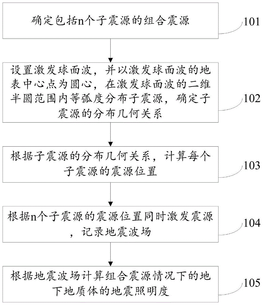
FIG. 1 is a schematic flow diagram of a combined seismic source excitation method for enhancing seismic illumination according to the present invention;
FIG. 2 is a schematic diagram of the combined seismic source enhanced seismic illumination of the present invention;
FIG. 3 is a schematic diagram of a combined source excitation system for enhancing seismic illumination according to the present invention.
Detailed Description
The technical solutions in the embodiments of the present invention will be clearly and completely described below with reference to the drawings in the embodiments of the present invention, and it is obvious that the described embodiments are only a part of the embodiments of the present invention, and not all of the embodiments. All other embodiments, which can be derived by a person skilled in the art from the embodiments given herein without making any creative effort, shall fall within the protection scope of the present invention.
The invention aims to provide a combined seismic source excitation method and a combined seismic source excitation system for enhancing seismic illumination, which can enhance the coherence of a seismic wave field along a propagation spherical surface by changing the position of a combined seismic source, and achieve the purpose of enhancing the seismic illumination intensity by a plurality of combined seismic sources.
In order to make the aforementioned objects, features and advantages of the present invention comprehensible, embodiments accompanied with figures are described in further detail below.
Example one
As shown in fig. 1, the present embodiment provides a combined seismic source excitation method for enhancing seismic illumination, which includes the following steps.
Step 101: determining a combined source comprising n sub-sources; the method specifically comprises the following steps:
determining the type of the sub seismic sources in the combined seismic source; wherein the type of the sub-seismic sources is a pulse point seismic source.
Determining the number of the sub seismic sources in the combined seismic source; wherein the number n of the sub seismic sources is an odd number.
Step 102: and setting an excitation spherical wave, distributing the sub seismic sources with equal radians within a two-dimensional semicircular range of the excitation spherical wave by taking the surface central point of the excitation spherical wave as a circle center, and determining the distribution geometric relationship of the sub seismic sources.
The method specifically comprises the following steps:
and setting an excitation spherical wave, and determining the radius of the excitation spherical wave to be r meters.
Under the two-dimensional condition of exciting spherical waves, the sub seismic sources are distributed in an equal radian mode within a semicircular range by taking the center point of the ground surface as the circle center, and the distribution geometric relationship of the sub seismic sources is determined. Wherein, the angle of the equal radian distribution of the semi-circle range is 180/(n-1).
Step 103: calculating the seismic source position of each sub seismic source according to the distribution geometric relationship of the sub seismic sources; wherein the seismic source position comprises a surface position and a well depth. The method specifically comprises the following steps:
and respectively calculating the surface position and the well depth of the n sub seismic sources according to the distribution geometrical relationship of the sub seismic sources by taking the surface as a horizontal plane.
Step 104: and simultaneously exciting the seismic sources according to the seismic source positions of the n sub seismic sources and recording the seismic wave field.
Step 105: the seismic illumination of the subsurface geologic volume in the case of a combined source is calculated from the seismic wavefield.
Example two
The combined seismic source excitation method for enhancing the seismic illumination provided by the embodiment comprises the following steps in the horizontal ground surface condition shown in fig. 2:
a. and adopting an impulse point seismic source as a unit of the combined seismic source.
b. Setting the number n of the sub seismic sources of the combined seismic source as an odd number; in the example of fig. 2, the number of the sub seismic sources for setting the combined seismic source is 7, and the surface position projection is s from left to right1、s2、s3、s4、s5、s6、s7。
c. The radius of the excitation spherical wave is set to be r m, the destruction effect of a spherical cavity excited by a pulse seismic source and the constructive interference effect of seismic waves are considered, and the radius of a circle is larger than 1 m and smaller than one-half wavelength under the two-dimensional condition.
d. In the two-dimensional case, the angle for calculating the equal radian distribution of the semicircular range is 180/(7-1) ═ 30 ° with the center point of the ground surface as the center, that is, θ in fig. 2 is 30 °.
e. According to the geometric relationship, the center position O of the earth surface is the coordinate midpoint and the seismic source s1Respectively has a surface position and a burial depth of s1x=-r,s 1z0; seismic source s2Respectively has a surface position and a burial depth of s2x=-rcosθ,s2zRsin θ; and sequentially calculating the surface positions and depths of all shot points, wherein the depth is used as the well depth of the excitation seismic source.
f. And simultaneously exciting the seismic sources according to the calculated positions of the seismic sources and recording the seismic wave fields.
g. Accumulating wave fields of all seismic sources as a basis for calculating the seismic illumination of the combined seismic sources, wherein an illumination calculation formula is as follows:
wherein E (x, z) is the calculated seismic illumination of the combined seismic source; n is the number of the seismic sources, and n is 7; nt is the number of discrete time sampling points recorded along the time direction;
is to calculate the current seismic source s according to the wave equation
iA snapshot (intensity) of the seismic wavefield;
is the variation of the spatial points over time.
As shown in FIG. 2, the seismic wavefield equivalent to the seismic source of the energy enhancing point can be calculated through steps a to g, so that the illumination intensity of the earthquake is enhanced.
EXAMPLE III
As shown in fig. 3, the present embodiment provides a combined source excitation system for enhancing seismic illumination, including:
a combined source determination module 201 for determining a combined source comprising n sub-sources; the method specifically comprises the following steps:
the type determining unit is used for determining the types of the sub seismic sources in the combined seismic source; wherein the type of the sub-seismic sources is a pulse point seismic source.
The number determining unit is used for determining the number of the sub seismic sources in the combined seismic source; wherein the number n of the sub seismic sources is an odd number.
And the sub-seismic source distribution module 202 is used for setting the excitation spherical wave, distributing the sub-seismic sources with equal radians within a two-dimensional semicircular range of the excitation spherical wave by taking the earth surface central point of the excitation spherical wave as a circle center, and determining the distribution geometric relationship of the sub-seismic sources. The method specifically comprises the following steps:
and the excitation spherical wave setting unit is used for setting the excitation spherical wave and determining that the radius of the excitation spherical wave is r meters.
And the sub-seismic source distribution unit is used for distributing sub-seismic sources with equal radians in a semicircular range by taking the center point of the ground surface as the center of a circle under the two-dimensional condition of exciting spherical waves and determining the distribution geometric relationship of the sub-seismic sources. Wherein, the angle of the equal radian distribution of the semi-circle range is 180/(n-1).
The seismic source position calculating module 203 is used for calculating the seismic source position of each sub seismic source according to the distribution geometric relationship of the sub seismic sources; wherein the seismic source position comprises a surface position and a well depth. The method specifically comprises the following steps:
and the seismic source position calculating unit is used for respectively calculating the surface position and the well depth of the n sub seismic sources by taking the surface as a horizontal plane according to the distribution geometrical relationship of the sub seismic sources.
And the seismic wave field recording module 204 is used for simultaneously exciting the seismic sources according to the seismic source positions of the n sub-seismic sources and recording the seismic wave field.
And the seismic illumination calculation module 205 is used for calculating the seismic illumination of the underground geologic body under the condition of the combined seismic source according to the seismic wave field.
The embodiments in the present description are described in a progressive manner, each embodiment focuses on differences from other embodiments, and the same and similar parts among the embodiments are referred to each other. For the system disclosed by the embodiment, the description is relatively simple because the system corresponds to the method disclosed by the embodiment, and the relevant points can be referred to the method part for description.
The principles and embodiments of the present invention have been described herein using specific examples, which are provided only to help understand the method and the core concept of the present invention; meanwhile, for a person skilled in the art, according to the idea of the present invention, the specific embodiments and the application range may be changed. In view of the above, the present disclosure should not be construed as limiting the invention.