US20050195686A1 - System for combining signals of pressure sensors and particle motion sensors in marine seismic streamers - Google Patents
System for combining signals of pressure sensors and particle motion sensors in marine seismic streamers Download PDFInfo
- Publication number
- US20050195686A1 US20050195686A1 US10/792,510 US79251004A US2005195686A1 US 20050195686 A1 US20050195686 A1 US 20050195686A1 US 79251004 A US79251004 A US 79251004A US 2005195686 A1 US2005195686 A1 US 2005195686A1
- Authority
- US
- United States
- Prior art keywords
- signal
- particle motion
- calculated
- sensors
- sensor
- Prior art date
- Legal status (The legal status is an assumption and is not a legal conclusion. Google has not performed a legal analysis and makes no representation as to the accuracy of the status listed.)
- Granted
Links
Images


Classifications
-
- G—PHYSICS
- G01—MEASURING; TESTING
- G01V—GEOPHYSICS; GRAVITATIONAL MEASUREMENTS; DETECTING MASSES OR OBJECTS; TAGS
- G01V1/00—Seismology; Seismic or acoustic prospecting or detecting
- G01V1/28—Processing seismic data, e.g. analysis, for interpretation, for correction
- G01V1/36—Effecting static or dynamic corrections on records, e.g. correcting spread; Correlating seismic signals; Eliminating effects of unwanted energy
- G01V1/364—Seismic filtering
- G01V1/366—Seismic filtering by correlation of seismic signals
-
- G—PHYSICS
- G01—MEASURING; TESTING
- G01V—GEOPHYSICS; GRAVITATIONAL MEASUREMENTS; DETECTING MASSES OR OBJECTS; TAGS
- G01V1/00—Seismology; Seismic or acoustic prospecting or detecting
- G01V1/38—Seismology; Seismic or acoustic prospecting or detecting specially adapted for water-covered areas
- G01V1/3808—Seismic data acquisition, e.g. survey design
-
- G—PHYSICS
- G01—MEASURING; TESTING
- G01V—GEOPHYSICS; GRAVITATIONAL MEASUREMENTS; DETECTING MASSES OR OBJECTS; TAGS
- G01V1/00—Seismology; Seismic or acoustic prospecting or detecting
- G01V1/28—Processing seismic data, e.g. analysis, for interpretation, for correction
- G01V1/284—Application of the shear wave component and/or several components of the seismic signal
Definitions
- This invention relates generally to the field of geophysical prospecting. More particularly, the invention relates to the field of marine seismic exploration. Specifically, the invention is a system for combining signals of pressure sensors and particle motion sensors in marine seismic streamers.
- geophysical data are obtained by applying acoustic energy to the earth from an acoustic source and detecting seismic energy reflected from interfaces between different layers in subsurface formations.
- the seismic wavefield is reflected when there is a difference in acoustic impedance between the layer above the interface and the layer below the interface.
- a seismic streamer is towed behind an exploration vessel at a water depth typically between about six to about nine meters, but can be towed shallower or deeper.
- Hydrophones are included in the streamer cable for detecting seismic signals.
- a hydrophone is a submersible pressure gradient sensor that converts pressure waves into electrical or optical signals that are typically recorded for signal processing, and evaluated to estimate characteristics of the subsurface of the earth.
- a plurality of streamer cables are towed behind a vessel.
- One or more seismic sources are also normally towed behind the vessel.
- the seismic source which typically is an airgun array, but may also be a water gun array or other type of source known to those of ordinary skill in the art, transmits seismic energy or waves into the earth and the waves are reflected back by reflectors in the earth and recorded by sensors in the streamers. Paravanes are typically employed to maintain the cables in the desired lateral position while being towed.
- the seismic cables are maintained at a substantially stationary position in a body of water, either floating at a selected depth or lying on the bottom of the body of water, in which case the source may be towed behind a vessel to generate acoustic energy at varying locations, or the source may also be maintained in a stationary position.
- the wave After the reflected wave reaches the streamer cable, the wave continues to propagate to the water/air interface at the water surface, from which the wave is reflected downwardly, and is again detected by the hydrophones in the streamer cable.
- the water surface is a good reflector and the reflection coefficient at the water surface is nearly unity in magnitude and is negative in sign for pressure signals.
- the waves reflected at the surface will thus be phase-shifted 180 degrees relative to the upwardly propagating waves.
- the downwardly propagating wave recorded by the receivers is commonly referred to as the surface reflection or the “ghost” signal. Because of the surface reflection, the water surface acts like a filter, which creates spectral notches in the recorded signal, making it difficult to record data outside a selected bandwidth. Because of the influence of the surface reflection, some frequencies in the recorded signal are amplified and some frequencies are attenuated.
- Maximum attenuation will occur at frequencies for which the propagation distance between the detecting hydrophone and the water surface is equal to one-half wavelength.
- Maximum amplification will occur at frequencies for which the propagation distance between the detecting hydrophone and the water surface is one-quarter wavelength.
- the wavelength of the acoustic wave is equal to the velocity divided by the frequency, and the velocity of an acoustic wave in water is about 1500 meters/second. Accordingly, the location in the frequency spectrum of the resulting spectral notch is readily determinable. For example, for a seismic streamer at a depth of 7 meters, and waves with vertical incidence, maximum attenuation will occur at a frequency of about 107 Hz and maximum amplification will occur at a frequency of about 54 Hz.
- a particle motion sensor such as a geophone
- a pressure sensor such as hydrophone
- the upgoing wavefield signals detected by a geophone and hydrophone located close together will be in phase, while the downgoing wavefield signals will be recorded 180 degrees out of phase.
- Various techniques have been proposed for using this phase difference to reduce the spectral notches caused by the surface reflection and, if the recordings are made on the seafloor, to attenuate water borne multiples. It should be noted that an alternative to having the geophone and hydrophone co-located, is to have sufficient spatial density of sensors so that the respective wavefields recorded by the hydrophone and geophone can be interpolated or extrapolated to produce the two wavefields at the same location.
- U.S. Pat. No. 4,486,865 to Ruehle teaches a system for suppressing ghost reflections by combining the outputs of pressure and velocity detectors.
- the detectors are paired, one pressure detector and one velocity detector in each pair.
- a filter is said to change the frequency content of at least one of the detectors so that the ghost reflections cancel when the outputs are combined.
- U.S. Pat. No. 5,621,700 to Moldovenu also teaches using at least one sensor pair comprising a pressure sensor and a velocity sensor in an ocean bottom cable in a method for attenuating ghosts and water layer reverberations.
- U.S. Pat. No. 4,935,903 to Sanders et al. teaches a marine seismic reflection prospecting system that detects seismic waves traveling in water by pressure sensor-particle velocity sensor pairs (e.g., hydrophone-geophone pairs) or alternately, vertically-spaced pressure sensors. Instead of filtering to eliminate ghost reflection data, the system calls for enhancing primary reflection data for use in pre-stack processing by adding ghost data.
- pressure sensor-particle velocity sensor pairs e.g., hydrophone-geophone pairs
- the system calls for enhancing primary reflection data for use in pre-stack processing by adding ghost data.
- U.S. Pat. No. 4,979,150 to Barr provides a method for marine seismic prospecting said to attenuate coherent noise resulting from water column reverberation by applying a scale factor to the output of a pressure transducer and a particle velocity transducer positioned substantially adjacent to one another in the water. It is stated in the patent that the transducers may be positioned either on the ocean bottom or at a location in the water above the bottom, although the ocean bottom is said to be preferred.
- pressure and particle motion signals can be combined to derive both the up-going and the down-going wavefield.
- the up-going and down-going wavefields may subsequently be combined to remove the effect of the surface reflection and to attenuate water borne multiples in the seismic signal.
- the particle motion signal has been regarded as having limited utility because of the high noise level in the particle motion signal.
- particle motion signals could be provided for towed streamer acquisition, the effect of the surface reflection could be removed from the data.
- the invention is a method for combining signals of pressure sensors and particle motion sensors located in marine seismic streamers. Then, a particle motion sensor signal is calculated at low frequencies from the pressure sensor signal, using the depth of the marine seismic streamer and the sound wave velocity in water.
- a full three-dimensional mathematical solution takes account of the fact that the energy returning from the earth arrives at the receivers at a range of angles of incidence, rather than solely in the in-line direction or at a given direction, such as the vertical.
- FIG. 1 is an illustration of a method for acquiring marine seismic data that can be used with the method of the invention
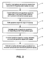
- FIG. 2 is a flowchart illustrating the processing steps of an embodiment of the method of the invention for combining signals of pressure sensors like hydrophones and particle motion sensors like geophones, located in a marine seismic streamer;
- FIG. 3 is a plot of a hydrophone signal recorded at 13 m depth.
- FIG. 4 is a plot of the corresponding geophone signal recorded simultaneously with the hydrophone signal in FIG. 2 ;
- FIG. 5 is a plot of the amplitude spectra of the hydrophone and geophone signals from FIGS. 2 and 3 , respectively;
- FIG. 6 is a plot of the amplitude spectra of the hydrophone and tapered geophone signals from FIG. 4 ;
- FIG. 7 is a plot of the amplitude spectra of the hydrophone and tapered geophone signals, as in FIG. 5 , and, in addition, a calculated and tapered geophone signal amplitude spectrum.
- FIG. 8 is a plot of the amplitude spectra of the hydrophone and merged geophone signals from FIG. 7 ;
- FIG. 9 is a plot of the amplitude spectra of the up-going wavefield generated by summing the hydrophone and geophone signals from FIG. 7 .
- FIG. 1 shows a schematic illustration (not drawn to scale) of a method for acquiring marine seismic data that can be used with the method of the invention.
- a seismic vessel 101 is located in a body of water 102 above the earth 103 . Beneath the water bottom 104 , the earth 103 contains subterranean formations of interest such as layer 105 positioned between upper boundary 106 and lower boundary 107 .
- the seismic vessel 101 travels on the water surface 108 and contains seismic acquisition control equipment, designated generally at 109 .
- the seismic acquisition control equipment 109 includes navigation control, seismic source control, seismic sensor control, and recording equipment, all of types well known in the art of seismic acquisition.
- the seismic acquisition control equipment 109 causes a seismic source 110 towed in the body of water 102 by the seismic vessel 101 to actuate at selected times.
- the seismic source 110 may be of any type well known in the art of seismic acquisition, including airguns or water guns, or particularly, arrays of airguns.
- Seismic streamers 111 are also towed in the body of water 102 by the seismic vessel 101 to record the acoustic wavefields initiated by the seismic source 110 and reflected from interfaces in the environment. Although only one seismic streamer 111 is shown here for illustrative purposes, typically a plurality of seismic streamers 111 are towed behind the seismic vessel 101 .
- the seismic streamers 111 contain sensors to detect the reflected wavefields initiated by the seismic source 110 .
- the seismic streamers 111 contained pressure sensors such as hydrophones 112 , but dual sensor seismic streamers 111 also contain water particle motion sensors such as geophones 113 .
- the hydrophones 112 and geophones 113 are typically co-located in pairs or pairs of sensor arrays at regular intervals along the seismic streamers 111 .
- the type of sensors 112 , 113 or their location in the seismic streamers 111 is not intended to be a limitation on the present invention.
- an acoustic wavefield travels both upwardly or downwardly in spherically expanding wave fronts.
- the propagation of the wave fronts will be illustrated herein by ray paths which are perpendicular to the wave fronts.
- the upwardly traveling wavefield designated by ray path 114 , will reflect off the water-air interface at the water surface 108 and then travel downwardly, as in ray path 115 , where the wavefield may be detected by the hydrophones 112 and geophones 113 in the seismic streamers 111 .
- ray path 115 contains no useful information about the subterranean formations of interest.
- such surface reflections also known as ghosts, act like secondary seismic sources with a time delay.
- the downwardly traveling wavefield, in ray path 116 will reflect off the earth-water interface at the water bottom 104 and then travel upwardly, as in ray path 117 , where the wavefield may be detected by the hydrophones 112 and geophones 113 .
- Such a reflection at the water bottom 104 as in ray path 117 , contains information about the water bottom 104 .
- Ray path 117 is an example of a primary reflection, having one reflection in the subterranean earth.
- the downwardly traveling wavefield may transmit through the water bottom 104 as in ray path 118 , reflect off a layer boundary, such as 107 , of a layer, such as 105 , and then travel upwardly, as in ray path 119 .
- the upwardly traveling wavefield, ray path 119 may then be detected by the hydrophones 112 and geophones 113 .
- Such a reflection off a layer boundary 107 contains useful information about a formation of interest 105 and is also an example of a primary reflection, having one reflection in the subterranean earth.
- the acoustic wavefields will continue to reflect off interfaces such as the water bottom 104 , water surface 108 , and layer boundaries 106 , 107 in combinations.
- the upwardly traveling wavefield in ray path 117 will reflect off the water surface 108 , continue traveling downwardly in ray path 120 , may reflect off the water bottom 104 , and continue traveling upwardly again in ray path 121 , where the wavefield may be detected by the hydrophones 112 and geophones 113 .
- Ray path 121 is an example of a multiple reflection, also called simply a “multiple”, having multiple reflections from interfaces.
- the upwardly traveling wavefield in ray path 119 will reflect off the water surface 108 , continue traveling downwardly in ray path 122 , may reflect off a layer boundary 106 and continue traveling upwardly again in ray path 123 , where the wavefield may be detected by the hydrophones 112 and geophones 113 .
- Ray path 123 is another example of a multiple reflection, also having multiple reflections in the subterranean earth. Multiple reflections contain redundant information about the formations of interest and commonly are removed from seismic data before further processing.
- the invention is a method for combining signals of pressure sensors (typically hydrophones) and particle motion sensors (typically geophones or accelerometers) located in seismic streamers.
- the combined signals can then be utilized to generate the up- and down-going wavefields, which are useful for further seismic processing, such as attenuation of multiples in marine seismic data. Since a recorded particle motion signal is often contaminated by low frequency noise due to the vibrations in a towed streamer, the signal-to-noise ratio for the combined signals would be poor.
- the particle motion signal may be calculated from the pressure sensor signal within a given frequency range if the spectrum of the pressure sensor signal has a satisfactory signal-to-noise ratio within this frequency range (and has no notches within this frequency range) and if the depth of the pressure and particle motion sensors is known. If the depth to the sensors is unknown, the depth can be calculated from the frequency of the spectral notches introduced by the surface reflection, a process which is well known in the art.
- the low frequency part of the particle motion signal will typically need to be replaced because it has a low signal-to-noise ratio.
- This low frequency part will be referred to as the ‘Frequency Range’.
- the corresponding portion of the pressure sensor signal to be used for calculating the particle motion signal will typically have a good signal-to-noise ratio in the Frequency Range. Therefore, the depth of the pressure sensor is preferably chosen so that the frequency of the first spectral notch in the pressure sensor signal caused by the surface reflection is higher than the Frequency Range.
- the method of the invention is particularly useful for towed marine seismic streamers, since the vibration of a towed streamer adds a significant amount of noise to the signal of the particle motion sensor.
- the method of the invention will be illustrated in terms of towed streamers.
- the method of the invention employs pressure sensors that are responsive to pressure changes in the medium to which the pressure sensors are coupled.
- the medium typically is water.
- the method of the invention will be illustrated by the use of hydrophones, but this is not meant to limit the invention.
- the method of the invention employs particle motion sensors that are responsive to motions in the particles of the water to which the motion sensors are coupled.
- particle motion sensors may be responsive to the displacement of the particles, the velocity of the particles, or the acceleration of the particles in the medium.
- particle velocity sensors are preferred.
- motion sensors are used which are responsive to position, then preferably the position signal is differentiated to convert it to a velocity signal by computational means well known in the art.
- motion sensors are used which are responsive to acceleration (typically called accelerometers), then preferably the acceleration signal is integrated to convert it to a velocity signal by computational means well known in the art.
- multi-component motion sensors are employed in the seismic cable.
- this embodiment of the invention will be illustrated by the use of geophones, but this is not meant to limit the invention.
- a geophone is mounted to sense particle velocity in the vertical direction. This geophone is called a vertical geophone. Two geophones are mounted in orthogonal directions with respect to each other, and to the vertically mounted geophone, to sense horizontal motion.
- a three-component geophone is oriented to sense motion in the vertical direction, in an in-line direction, and in a cross-line direction. Positioning these geophones in these three directions enables the propagation direction of an incoming signal to be detected. It also enables the detection of strumming or other mechanical behavior of the seismic cable.
- the method of the invention will be illustrated by the use of vertical geophones, but this is not meant to limit the invention.
- Accelerometers could be used as particle motion sensors as an alternative to use of geophones, although the output signal will need to be integrated to obtain velocity. Some accelerometers generate an output signal that is indicative of the variation in orientation of the accelerometer from a selected orientation. Accordingly, if sets of two accelerometers (for situations in which the in-line direction is known) or sets of three accelerometers (if the in-line direction is not known) are utilized, the sensor orientation may be computed and it is not necessary to maintain the accelerometers in a specific orientation.
- the method of the invention will be illustrated by the discussion with reference to the flowchart presented in FIG. 2 .
- the method of the invention is illustrated herein by the use of hydrophones as pressure sensors and vertical geophones as particle motion sensors, but this is not meant to limit the invention.
- the hydrophone and geophone systems are positioned 0.7 m apart in a towed seismic streamer with a length of 1300 m, at a depth of 13 m, and with a seismic source at a depth of 7 m.
- the horizontal distance between the source and the hydrophone/geophone systems was approximately 1300 m.
- the specifics of these examples are for illustrative purposes only and are not intended to limit the invention.
- FIG. 2 shows a flowchart illustrating the processing steps of an embodiment of the method of the invention for calculating a geophone signal from a hydrophone signal and then combining signals from hydrophones and geophones located in marine seismic streamers.
- signals in the space-time domain are denoted by lower case letters, while the same signals in the frequency wave-number domain are denoted by the corresponding upper case (capital) letters.
- ⁇ overscore (x) ⁇ (space) is a vector and equal to (x, y), where x is the direction along the streamers and y is the cross line direction.
- y can be kept constant so that each cable is analyzed separately. One possible reason to select this option could be that the cables are deployed at significant different depths.
- x can be kept constant so that each sensor is analyzed individually. The latter will typically be a preferred option if the depth of the sensors within each cable varies significantly.
- ⁇ overscore (k) ⁇ (wave number) is a vector and equal to (k x , k y ), where k x is the wave number in the x direction and k y is the wave number in the y direction.
- k y can be disregarded so that each cable is analyzed separately. In this case a fixed direction of cross line propagation for each cable is selected. This direction could be vertical or any other direction. One possible reason to select this option could be that the cables are deployed at significantly different depths. Also, in other embodiments, both k x and k y can be disregarded so that each sensor is analyzed individually and only the frequency spectrum of each recorded trace is used.
- a set of hydrophone data h signal ( ⁇ overscore (x) ⁇ ,t) and a corresponding set of geophone data g signal ( ⁇ overscore (x) ⁇ ,t) are transformed from the space-time domain to the frequency-wave number domain, yielding a transformed hydrophone signal H signal (f, ⁇ overscore (k) ⁇ ) and a transformed geophone signal G signal (f, ⁇ overscore (k) ⁇ ), respectively.
- the transform is a Fourier Transform, but this is not a restriction of the invention.
- the method of the invention can be carried out in a variety of transformed domains, which separate the wavefield into angular components, including, but not limited to, wave number or slowness.
- the method of the invention is not restricted solely to the frequency-wave number domain or to Fourier transforms.
- the frequency-wave number domain and the Fourier transform are merely used in the following for illustrative purposes.
- the transformed hydrophone and geophone signals, H signal (f, ⁇ overscore (k) ⁇ ) and G signal (f, ⁇ overscore (k) ⁇ ), respectively, from step 21 are corrected for relative differences in the instrument transfer functions, which correspond to instrument impulse responses in the time domain.
- These corrections could either be correcting the amplitude and phase of the hydrophone data to match the geophone data, or, in an alternative embodiment, correcting the geophone data to match the hydrophone data, or, in a further alternative embodiment, correcting both data sets to a common basis. Correcting for relative differences in instrument impulse responses is well known in the art.
- an amplitude scaling equal to the inverse of the acoustic impedance in the water is preferably applied to the geophone data to correct for the relative differences in amplitudes of pressure and particle velocity. This is also well known in the art.
- G total ⁇ ( f , k _ ) G signal ⁇ ( f , k _ ) cos ⁇ ⁇ ⁇ , ( 1 )
- G total (f, ⁇ overscore (k) ⁇ ) is the total wavefield
- v is the velocity of sound in the water.
- Equation (2) shows a direct link between the angle of incident ⁇ and values of wave number k and frequency f If v is not known for some reason, then it can be measured by methods well known in the art. Also, it can be seen from Equation (2) that cos( ⁇ ) is real and different from zero for values of k given by: 0 ⁇ ⁇ k ⁇ ⁇ f v . ( 3 )
- FIGS. 3 and 4 Examples of single trace recordings where the corrections above have been applied (assuming vertical incident angle) are shown in FIGS. 3 and 4 .
- FIG. 3 is a plot of amplitude versus time for a hydrophone signal recorded at 13 m depth.
- FIG. 4 is a plot of amplitude versus time for the corresponding geophone signal recorded simultaneously with the hydrophone signal from FIG. 3 .
- the corresponding amplitude spectra (showing amplitude versus frequency) of the hydrophone and geophone signals are shown in FIG. 5 .
- the solid line 51 is the spectrum of the hydrophone signal and the dotted line 52 is the spectrum of the geophone signal.
- the higher noise level in the geophone data can be seen by comparison of FIGS. 3 and 4 .
- FIG. 5 it can be seen from FIG. 5 that the noise in the geophone signals is mainly confined to the lower frequencies 53 .
- a low frequency part of the geophone signal is calculated from the recorded hydrophone signal.
- a data set G calculated (f, ⁇ overscore (k) ⁇ ) is generated from H signal (f, ⁇ overscore (k) ⁇ ) for f 1 ⁇ f ⁇ f 2 , that is, for a Frequency Range [f 1 ,f 2 ]. In the following this procedure is described in detail.
- Equation (6) Equation (6)
- ⁇ be the surface reflection time delay, that is, the time delay between the direct upward propagating arrival of the wavefield and the corresponding reflection from the surface.
- D is the depth of the hydrophone and the geophone.
- the depth D may be determined by any means known in the art, such as by a depth sensor or a calculation. Assume that the reflection coefficient at the sea surface is c for pressure signals and, thus, ⁇ c for particle velocity signals.
- the hydrophone and geophone signals expressed in terms of their up-going and down-going components in Equations (11) and (12) are transformed to the frequency-wave number domain.
- the transform is a Fourier Transform, but this is not a restriction of the invention.
- Equation (16) Equation (16 ) where frequency f is given by f 1 ⁇ f ⁇ f 2 and wave number k is as in Equation (3). Equation (16) may be used to calculate a geophone signal from the recorded hydrophone signal at low frequencies where the signal-to-noise ratio of the recorded geophone signal is insufficient for processing needs.
- the difference between f 2 and f noise should be large enough so that the calculated geophone signal from (16) can be compared and checked with the measured geophone signal.
- a range of overlapping frequencies is preferred to merge the calculated portion of the geophone signal with the measured portion.
- f 2 should be 5-10 Hz larger than f noise .
- f 2 should be significantly lower than v/2D and preferably not larger than around 75% of v/2D.
- the depth D of the sensors is 13 m. Assuming a water velocity v of 1500 m/s gives a first notch in the hydrophone spectrum at around v/2D, or about 58 Hz. This indicates that f 2 should be less than around 75% of v/2D, or about 43 Hz.
- step 25 in FIG. 2 the calculated and the recorded part of the geophone signal are merged into one data set.
- the merger should preferably be done with a tapering zone. In practice this tapering zone will be the frequencies between f noise and f 2 , even if a narrower frequency zone can be selected.
- G constructed ⁇ ( f , k _ ) ⁇ G calculated ⁇ ( f , k _ ) , for ⁇ ⁇ f ⁇ f noise , [ 1 - w ⁇ ( f ) ] ⁇ G calculated ( f , k _ ) + w ⁇ ( f ) ⁇ G total ⁇ ( f , k _ ) , for ⁇ ⁇ f noise ⁇ f ⁇ f 2 , G total ⁇ ( f , k _ ) , for ⁇ ⁇ f > f 2 . ( 20 )
- FIG. 6 is a plot of the amplitude spectra of the hydrophone and geophone signals from FIG. 5 .
- the solid line 61 is the spectrum of the hydrophone signal and the dotted line 62 is the spectrum of the geophone signal.
- FIG. 7 includes a geophone signal 73 which has been calculated from the hydrophone signal from equation (11) in the 3-25 Hz frequency range, and linearly tapered on the low frequency side and between 20 and 25 Hz.
- the solid line 71 is the spectrum of the hydrophone signal and the dotted line 72 is the spectrum of the geophone signal taken from FIG. 6 .
- FIG. 8 shows the amplitude spectra of the recorded hydrophone data 81 and the merged (constructed) geophone data 82 .
- the geophone signal 82 has been merged using Equation (20). It can be seen that the hydrophone and geophone data sets now have essentially the same bandwidth.
- step 26 in FIG. 2 the full bandwidth constructed geophone data set and full bandwidth recorded hydrophone data set are added or subtracted to calculate the full bandwidth up- and down-going wavefield, respectively.
- The amplitude spectrum of the up-going wavefield,
- The notch 91 at around 125 Hz is the surface reflection notch at the source side with the source at around 6 m depth.
Abstract
Description
- Not Applicable
- Not Applicable
- Not Applicable
- 1. Field of the Invention
- This invention relates generally to the field of geophysical prospecting. More particularly, the invention relates to the field of marine seismic exploration. Specifically, the invention is a system for combining signals of pressure sensors and particle motion sensors in marine seismic streamers.
- 2. Description of the Related Art
- In seismic exploration, geophysical data are obtained by applying acoustic energy to the earth from an acoustic source and detecting seismic energy reflected from interfaces between different layers in subsurface formations. The seismic wavefield is reflected when there is a difference in acoustic impedance between the layer above the interface and the layer below the interface. When using towed streamers in marine seismic exploration, a seismic streamer is towed behind an exploration vessel at a water depth typically between about six to about nine meters, but can be towed shallower or deeper. Hydrophones are included in the streamer cable for detecting seismic signals. A hydrophone is a submersible pressure gradient sensor that converts pressure waves into electrical or optical signals that are typically recorded for signal processing, and evaluated to estimate characteristics of the subsurface of the earth.
- In a typical geophysical exploration configuration, a plurality of streamer cables are towed behind a vessel. One or more seismic sources are also normally towed behind the vessel. The seismic source, which typically is an airgun array, but may also be a water gun array or other type of source known to those of ordinary skill in the art, transmits seismic energy or waves into the earth and the waves are reflected back by reflectors in the earth and recorded by sensors in the streamers. Paravanes are typically employed to maintain the cables in the desired lateral position while being towed. Alternatively, the seismic cables are maintained at a substantially stationary position in a body of water, either floating at a selected depth or lying on the bottom of the body of water, in which case the source may be towed behind a vessel to generate acoustic energy at varying locations, or the source may also be maintained in a stationary position.
- After the reflected wave reaches the streamer cable, the wave continues to propagate to the water/air interface at the water surface, from which the wave is reflected downwardly, and is again detected by the hydrophones in the streamer cable. The water surface is a good reflector and the reflection coefficient at the water surface is nearly unity in magnitude and is negative in sign for pressure signals. The waves reflected at the surface will thus be phase-shifted 180 degrees relative to the upwardly propagating waves. The downwardly propagating wave recorded by the receivers is commonly referred to as the surface reflection or the “ghost” signal. Because of the surface reflection, the water surface acts like a filter, which creates spectral notches in the recorded signal, making it difficult to record data outside a selected bandwidth. Because of the influence of the surface reflection, some frequencies in the recorded signal are amplified and some frequencies are attenuated.
- Maximum attenuation will occur at frequencies for which the propagation distance between the detecting hydrophone and the water surface is equal to one-half wavelength. Maximum amplification will occur at frequencies for which the propagation distance between the detecting hydrophone and the water surface is one-quarter wavelength. The wavelength of the acoustic wave is equal to the velocity divided by the frequency, and the velocity of an acoustic wave in water is about 1500 meters/second. Accordingly, the location in the frequency spectrum of the resulting spectral notch is readily determinable. For example, for a seismic streamer at a depth of 7 meters, and waves with vertical incidence, maximum attenuation will occur at a frequency of about 107 Hz and maximum amplification will occur at a frequency of about 54 Hz.
- It has not been common practice to tow streamer cables deeper than about nine meters because the location of the spectral notch in the frequency spectrum of the signal detected by a hydrophone substantially diminishes the utility of the recorded data. It has also not been common practice to tow streamer cables at depth less than six meters, because of the significant increase in surface related noise induced in the seismic streamer data.
- It is also common to perform marine seismic operations in which sensors are deployed at the water bottom. Such operations are typically referred to as “ocean bottom seismic” operations. In ocean bottom seismic operations, both pressure sensors (hydrophones) and particle motion sensors (geophones, accelerometers) are deployed at the ocean floor to record seismic data.
- A particle motion sensor, such as a geophone, has directional sensitivity, whereas a pressure sensor, such as hydrophone, does not. Accordingly, the upgoing wavefield signals detected by a geophone and hydrophone located close together will be in phase, while the downgoing wavefield signals will be recorded 180 degrees out of phase. Various techniques have been proposed for using this phase difference to reduce the spectral notches caused by the surface reflection and, if the recordings are made on the seafloor, to attenuate water borne multiples. It should be noted that an alternative to having the geophone and hydrophone co-located, is to have sufficient spatial density of sensors so that the respective wavefields recorded by the hydrophone and geophone can be interpolated or extrapolated to produce the two wavefields at the same location.
- U.S. Pat. No. 4,486,865 to Ruehle, for example, teaches a system for suppressing ghost reflections by combining the outputs of pressure and velocity detectors. The detectors are paired, one pressure detector and one velocity detector in each pair. A filter is said to change the frequency content of at least one of the detectors so that the ghost reflections cancel when the outputs are combined.
- U.S. Pat. No. 5,621,700 to Moldovenu also teaches using at least one sensor pair comprising a pressure sensor and a velocity sensor in an ocean bottom cable in a method for attenuating ghosts and water layer reverberations.
- U.S. Pat. No. 4,935,903 to Sanders et al. teaches a marine seismic reflection prospecting system that detects seismic waves traveling in water by pressure sensor-particle velocity sensor pairs (e.g., hydrophone-geophone pairs) or alternately, vertically-spaced pressure sensors. Instead of filtering to eliminate ghost reflection data, the system calls for enhancing primary reflection data for use in pre-stack processing by adding ghost data.
- U.S. Pat. No. 4,979,150 to Barr provides a method for marine seismic prospecting said to attenuate coherent noise resulting from water column reverberation by applying a scale factor to the output of a pressure transducer and a particle velocity transducer positioned substantially adjacent to one another in the water. It is stated in the patent that the transducers may be positioned either on the ocean bottom or at a location in the water above the bottom, although the ocean bottom is said to be preferred.
- Co-pending U.S. patent application Ser. No. 10/233,266, filed on Aug. 30, 2002, entitled “Apparatus and Method for Multicomponent Marine Geophysical Data Gathering”, with a co-inventor of the present invention and assigned to the assignee of the present invention, describes a particle motion sensor for use in a streamer cable and a method for equalizing and combining the output signals of the particle motion sensor and a co-located pressure gradient sensor.
- As the cited patents show, it is well known in the art that pressure and particle motion signals can be combined to derive both the up-going and the down-going wavefield. For sea floor recordings, the up-going and down-going wavefields may subsequently be combined to remove the effect of the surface reflection and to attenuate water borne multiples in the seismic signal. For towed streamer applications, however, the particle motion signal has been regarded as having limited utility because of the high noise level in the particle motion signal. However, if particle motion signals could be provided for towed streamer acquisition, the effect of the surface reflection could be removed from the data.
- Co-pending U.S. patent application Ser. No. 10/621,222, filed on Jul. 16, 2003, entitled “Method for Seismic Exploration Utilizing Motion Sensor and Pressure Sensor Data”, with a co-inventor of the present invention and assigned to the assignee of the present invention, describes a procedure for attenuating multiples by combining up- and down-going wavefields, measured in the water column, where the wavefields are calculated from combining pressure sensors like hydrophones and motion sensors like geophones. The procedure assumes, however, that both the pressure and the motion data have the same bandwidth.
- It has been difficult to achieve the same bandwidth in the motion sensor data as in the pressure sensor data, however, because of the noise induced by vibrations in the streamer, which is sensed by the particle motion sensors. The noise is, however, mainly confined to lower frequencies. One way to reduce the noise is to have several sensors in series or in parallel. This approach, however, does not always reduce the noise enough to yield a signal-to-noise ratio satisfactory for further seismic processing.
- Thus, a need exists for a method for obtaining a useful particle motion signal with a satisfactory signal-to-noise ratio at low frequencies. In particular, a need exists for a method to generate a particle motion signal with substantially the same bandwidth as a recorded pressure signal, for particle motion and pressure sensors located in a towed marine seismic streamer.
- The invention is a method for combining signals of pressure sensors and particle motion sensors located in marine seismic streamers. Then, a particle motion sensor signal is calculated at low frequencies from the pressure sensor signal, using the depth of the marine seismic streamer and the sound wave velocity in water.
- In a further embodiment of the invention, a full three-dimensional mathematical solution takes account of the fact that the energy returning from the earth arrives at the receivers at a range of angles of incidence, rather than solely in the in-line direction or at a given direction, such as the vertical.
- The invention and its advantages may be more easily understood by reference to the following detailed description and the attached drawings, in which:
-
FIG. 1 is an illustration of a method for acquiring marine seismic data that can be used with the method of the invention; -
FIG. 2 is a flowchart illustrating the processing steps of an embodiment of the method of the invention for combining signals of pressure sensors like hydrophones and particle motion sensors like geophones, located in a marine seismic streamer; -
FIG. 3 is a plot of a hydrophone signal recorded at 13 m depth. -
FIG. 4 is a plot of the corresponding geophone signal recorded simultaneously with the hydrophone signal inFIG. 2 ; -
FIG. 5 is a plot of the amplitude spectra of the hydrophone and geophone signals fromFIGS. 2 and 3 , respectively; -
FIG. 6 is a plot of the amplitude spectra of the hydrophone and tapered geophone signals fromFIG. 4 ; -
FIG. 7 is a plot of the amplitude spectra of the hydrophone and tapered geophone signals, as inFIG. 5 , and, in addition, a calculated and tapered geophone signal amplitude spectrum. -
FIG. 8 is a plot of the amplitude spectra of the hydrophone and merged geophone signals fromFIG. 7 ; and -
FIG. 9 is a plot of the amplitude spectra of the up-going wavefield generated by summing the hydrophone and geophone signals fromFIG. 7 . - While the invention will be described in connection with its preferred embodiments, it will be understood that the invention is not limited to these. On the contrary, the invention is intended to cover all alternatives, modifications, and equivalents that may be included within the scope of the invention, as defined by the appended claims.
-
FIG. 1 shows a schematic illustration (not drawn to scale) of a method for acquiring marine seismic data that can be used with the method of the invention. Aseismic vessel 101 is located in a body ofwater 102 above theearth 103. Beneath thewater bottom 104, theearth 103 contains subterranean formations of interest such aslayer 105 positioned betweenupper boundary 106 andlower boundary 107. Theseismic vessel 101 travels on thewater surface 108 and contains seismic acquisition control equipment, designated generally at 109. The seismicacquisition control equipment 109 includes navigation control, seismic source control, seismic sensor control, and recording equipment, all of types well known in the art of seismic acquisition. - The seismic
acquisition control equipment 109 causes aseismic source 110 towed in the body ofwater 102 by theseismic vessel 101 to actuate at selected times. Theseismic source 110 may be of any type well known in the art of seismic acquisition, including airguns or water guns, or particularly, arrays of airguns.Seismic streamers 111 are also towed in the body ofwater 102 by theseismic vessel 101 to record the acoustic wavefields initiated by theseismic source 110 and reflected from interfaces in the environment. Although only oneseismic streamer 111 is shown here for illustrative purposes, typically a plurality ofseismic streamers 111 are towed behind theseismic vessel 101. Theseismic streamers 111 contain sensors to detect the reflected wavefields initiated by theseismic source 110. Conventionally, theseismic streamers 111 contained pressure sensors such ashydrophones 112, but dual sensorseismic streamers 111 also contain water particle motion sensors such asgeophones 113. Thehydrophones 112 andgeophones 113 are typically co-located in pairs or pairs of sensor arrays at regular intervals along theseismic streamers 111. However, the type ofsensors seismic streamers 111 is not intended to be a limitation on the present invention. - Each time the
seismic source 110 is actuated, an acoustic wavefield travels both upwardly or downwardly in spherically expanding wave fronts. The propagation of the wave fronts will be illustrated herein by ray paths which are perpendicular to the wave fronts. The upwardly traveling wavefield, designated byray path 114, will reflect off the water-air interface at thewater surface 108 and then travel downwardly, as inray path 115, where the wavefield may be detected by thehydrophones 112 andgeophones 113 in theseismic streamers 111. Unfortunately, such a reflection at thewater surface 108, as inray path 115 contains no useful information about the subterranean formations of interest. However, such surface reflections, also known as ghosts, act like secondary seismic sources with a time delay. - The downwardly traveling wavefield, in
ray path 116, will reflect off the earth-water interface at thewater bottom 104 and then travel upwardly, as inray path 117, where the wavefield may be detected by thehydrophones 112 andgeophones 113. Such a reflection at thewater bottom 104, as inray path 117, contains information about thewater bottom 104.Ray path 117 is an example of a primary reflection, having one reflection in the subterranean earth. The downwardly traveling wavefield, as inray path 116, may transmit through thewater bottom 104 as inray path 118, reflect off a layer boundary, such as 107, of a layer, such as 105, and then travel upwardly, as inray path 119. The upwardly traveling wavefield,ray path 119, may then be detected by thehydrophones 112 andgeophones 113. Such a reflection off alayer boundary 107 contains useful information about a formation ofinterest 105 and is also an example of a primary reflection, having one reflection in the subterranean earth. - Unfortunately, the acoustic wavefields will continue to reflect off interfaces such as the
water bottom 104,water surface 108, andlayer boundaries ray path 117 will reflect off thewater surface 108, continue traveling downwardly inray path 120, may reflect off thewater bottom 104, and continue traveling upwardly again inray path 121, where the wavefield may be detected by thehydrophones 112 andgeophones 113.Ray path 121 is an example of a multiple reflection, also called simply a “multiple”, having multiple reflections from interfaces. Similarly, the upwardly traveling wavefield inray path 119 will reflect off thewater surface 108, continue traveling downwardly inray path 122, may reflect off alayer boundary 106 and continue traveling upwardly again inray path 123, where the wavefield may be detected by thehydrophones 112 andgeophones 113.Ray path 123 is another example of a multiple reflection, also having multiple reflections in the subterranean earth. Multiple reflections contain redundant information about the formations of interest and commonly are removed from seismic data before further processing. - The invention is a method for combining signals of pressure sensors (typically hydrophones) and particle motion sensors (typically geophones or accelerometers) located in seismic streamers. The combined signals can then be utilized to generate the up- and down-going wavefields, which are useful for further seismic processing, such as attenuation of multiples in marine seismic data. Since a recorded particle motion signal is often contaminated by low frequency noise due to the vibrations in a towed streamer, the signal-to-noise ratio for the combined signals would be poor. The particle motion signal may be calculated from the pressure sensor signal within a given frequency range if the spectrum of the pressure sensor signal has a satisfactory signal-to-noise ratio within this frequency range (and has no notches within this frequency range) and if the depth of the pressure and particle motion sensors is known. If the depth to the sensors is unknown, the depth can be calculated from the frequency of the spectral notches introduced by the surface reflection, a process which is well known in the art.
- The low frequency part of the particle motion signal will typically need to be replaced because it has a low signal-to-noise ratio. This low frequency part will be referred to as the ‘Frequency Range’. The corresponding portion of the pressure sensor signal to be used for calculating the particle motion signal, will typically have a good signal-to-noise ratio in the Frequency Range. Therefore, the depth of the pressure sensor is preferably chosen so that the frequency of the first spectral notch in the pressure sensor signal caused by the surface reflection is higher than the Frequency Range.
- The method of the invention is particularly useful for towed marine seismic streamers, since the vibration of a towed streamer adds a significant amount of noise to the signal of the particle motion sensor. Thus the method of the invention will be illustrated in terms of towed streamers.
- The method of the invention employs pressure sensors that are responsive to pressure changes in the medium to which the pressure sensors are coupled. The medium typically is water. For clarity only, the method of the invention will be illustrated by the use of hydrophones, but this is not meant to limit the invention.
- The method of the invention employs particle motion sensors that are responsive to motions in the particles of the water to which the motion sensors are coupled. In general, particle motion sensors may be responsive to the displacement of the particles, the velocity of the particles, or the acceleration of the particles in the medium. In the present invention, particle velocity sensors are preferred. Thus, if motion sensors are used which are responsive to position, then preferably the position signal is differentiated to convert it to a velocity signal by computational means well known in the art. If motion sensors are used which are responsive to acceleration (typically called accelerometers), then preferably the acceleration signal is integrated to convert it to a velocity signal by computational means well known in the art.
- In an alternative embodiment of the invention, multi-component motion sensors are employed in the seismic cable. For clarity only, this embodiment of the invention will be illustrated by the use of geophones, but this is not meant to limit the invention. In the particular example of a three-component geophone, a geophone is mounted to sense particle velocity in the vertical direction. This geophone is called a vertical geophone. Two geophones are mounted in orthogonal directions with respect to each other, and to the vertically mounted geophone, to sense horizontal motion. Typically, a three-component geophone is oriented to sense motion in the vertical direction, in an in-line direction, and in a cross-line direction. Positioning these geophones in these three directions enables the propagation direction of an incoming signal to be detected. It also enables the detection of strumming or other mechanical behavior of the seismic cable. For clarity, the method of the invention will be illustrated by the use of vertical geophones, but this is not meant to limit the invention.
- Accelerometers could be used as particle motion sensors as an alternative to use of geophones, although the output signal will need to be integrated to obtain velocity. Some accelerometers generate an output signal that is indicative of the variation in orientation of the accelerometer from a selected orientation. Accordingly, if sets of two accelerometers (for situations in which the in-line direction is known) or sets of three accelerometers (if the in-line direction is not known) are utilized, the sensor orientation may be computed and it is not necessary to maintain the accelerometers in a specific orientation.
- The method of the invention will be illustrated by the discussion with reference to the flowchart presented in
FIG. 2 . The method of the invention is illustrated herein by the use of hydrophones as pressure sensors and vertical geophones as particle motion sensors, but this is not meant to limit the invention. In the examples discussed below with reference toFIGS. 3-9 , the hydrophone and geophone systems are positioned 0.7 m apart in a towed seismic streamer with a length of 1300 m, at a depth of 13 m, and with a seismic source at a depth of 7 m. The horizontal distance between the source and the hydrophone/geophone systems was approximately 1300 m. The specifics of these examples are for illustrative purposes only and are not intended to limit the invention. -
FIG. 2 shows a flowchart illustrating the processing steps of an embodiment of the method of the invention for calculating a geophone signal from a hydrophone signal and then combining signals from hydrophones and geophones located in marine seismic streamers. - In the following discussion, signals in the space-time domain are denoted by lower case letters, while the same signals in the frequency wave-number domain are denoted by the corresponding upper case (capital) letters.
- In the preferred embodiment of the invention, {overscore (x)} (space) is a vector and equal to (x, y), where x is the direction along the streamers and y is the cross line direction. In other embodiments y can be kept constant so that each cable is analyzed separately. One possible reason to select this option could be that the cables are deployed at significant different depths. Also, in other embodiments, also x can be kept constant so that each sensor is analyzed individually. The latter will typically be a preferred option if the depth of the sensors within each cable varies significantly.
- In the preferred embodiment of the invention, {overscore (k)} (wave number) is a vector and equal to (kx, ky), where kx is the wave number in the x direction and ky is the wave number in the y direction. In other embodiments, ky can be disregarded so that each cable is analyzed separately. In this case a fixed direction of cross line propagation for each cable is selected. This direction could be vertical or any other direction. One possible reason to select this option could be that the cables are deployed at significantly different depths. Also, in other embodiments, both kx and ky can be disregarded so that each sensor is analyzed individually and only the frequency spectrum of each recorded trace is used. In this case a fixed direction of propagation in both the in-line and cross-line direction is used for each sensor. The latter will typically be a preferred option if the depth of the sensors within each cable varies significantly. In this case the transformed data will be in the f-x domain.
- The discussion below uses examples from marine seismic exploration for targets at depths from a few hundred meters to a few kilometers, so called deep seismic exploration. The present invention is, however, applicable to exploration for both shallower and deeper targets.
- At
step 21 ofFIG. 2 , a set of hydrophone data hsignal({overscore (x)},t) and a corresponding set of geophone data gsignal({overscore (x)},t) are transformed from the space-time domain to the frequency-wave number domain, yielding a transformed hydrophone signal Hsignal(f,{overscore (k)}) and a transformed geophone signal Gsignal(f,{overscore (k)}), respectively. Preferably, the transform is a Fourier Transform, but this is not a restriction of the invention. - The method of the invention can be carried out in a variety of transformed domains, which separate the wavefield into angular components, including, but not limited to, wave number or slowness. The method of the invention is not restricted solely to the frequency-wave number domain or to Fourier transforms. The frequency-wave number domain and the Fourier transform are merely used in the following for illustrative purposes.
- At
step 22 inFIG. 2 , the transformed hydrophone and geophone signals, Hsignal(f,{overscore (k)}) and Gsignal(f,{overscore (k)}), respectively, fromstep 21 are corrected for relative differences in the instrument transfer functions, which correspond to instrument impulse responses in the time domain. These corrections could either be correcting the amplitude and phase of the hydrophone data to match the geophone data, or, in an alternative embodiment, correcting the geophone data to match the hydrophone data, or, in a further alternative embodiment, correcting both data sets to a common basis. Correcting for relative differences in instrument impulse responses is well known in the art. Finally, an amplitude scaling equal to the inverse of the acoustic impedance in the water is preferably applied to the geophone data to correct for the relative differences in amplitudes of pressure and particle velocity. This is also well known in the art. - At
step 23 inFIG. 2 , the corrected geophone signal Gsignal(f,{overscore (k)}) fromstep 22 is further corrected for angle of incidence. While a hydrophone records the total wavefield, a vertical geophone will only record the vertical part of the wavefield. This will be equal to the total wavefield only for signals which are propagating vertically, i.e. for which the angle of incidence Φ=0. For any other values of Φ, the geophone signal needs to be scaled by:
where Gtotal(f,{overscore (k)}) is the total wavefield, and cos(Φ) is given by:
and v is the velocity of sound in the water. - The velocity of sound in the water is well known in the art to be close to 1500 m/sec. So, if v is known, then Equation (2) shows a direct link between the angle of incident Φ and values of wave number k and frequency f If v is not known for some reason, then it can be measured by methods well known in the art. Also, it can be seen from Equation (2) that cos(Φ) is real and different from zero for values of k given by:
- Examples of single trace recordings where the corrections above have been applied (assuming vertical incident angle) are shown in
FIGS. 3 and 4 .FIG. 3 is a plot of amplitude versus time for a hydrophone signal recorded at 13 m depth.FIG. 4 is a plot of amplitude versus time for the corresponding geophone signal recorded simultaneously with the hydrophone signal fromFIG. 3 . The corresponding amplitude spectra (showing amplitude versus frequency) of the hydrophone and geophone signals are shown inFIG. 5 . Thesolid line 51 is the spectrum of the hydrophone signal and the dottedline 52 is the spectrum of the geophone signal. The higher noise level in the geophone data can be seen by comparison ofFIGS. 3 and 4 . Also, it can be seen fromFIG. 5 that the noise in the geophone signals is mainly confined to thelower frequencies 53. - In
step 24 inFIG. 2 , a low frequency part of the geophone signal is calculated from the recorded hydrophone signal. Thus, a data set Gcalculated(f,{overscore (k)}) is generated from Hsignal(f,{overscore (k)}) for f1≦f≦f2, that is, for a Frequency Range [f1,f2]. In the following this procedure is described in detail. - The hydrophone signal and the geophone signal can be expressed in terms of their up-going and down-going components and the hydrophone signal (pressure wavefield) is given by the equation:
h signal({overscore (x)},t)=h↑({overscore (x)},t)+h↓({overscore (x)},t). (4)
where h↑({overscore (x)},t) is the up-going component and h↓({overscore (x)},t) is the down-going component, respectively, of the hydrophone signal hsignal({overscore (x)},t). Similarly, the geophone signal (velocity wavefield) is given by:
g signal({overscore (x)},t)=g↑({overscore (x)},t)+g↓({overscore (x)},t), (5)
where g↑({overscore (x)},t) is the up-going component and g↓({overscore (x)},t) is the down-going component, respectively, of the geophone signal gsignal({overscore (x)},t). - Assume that the up-going components of the hydrophone and geophone signals are the same, that is,
h↑({overscore (x)},t)=g↑({overscore (x)},t). (6)
Then, inserting Equation (6) into Equation (5) yields:
g signal({overscore (x)},t)=h↑({overscore (x)},t)+g↓({overscore (x)},t) (7) - Let τ be the surface reflection time delay, that is, the time delay between the direct upward propagating arrival of the wavefield and the corresponding reflection from the surface. Using the definition of cos(Φ) given by Equation (2), the time delay τ is given by:
where D is the depth of the hydrophone and the geophone. The depth D may be determined by any means known in the art, such as by a depth sensor or a calculation. Assume that the reflection coefficient at the sea surface is c for pressure signals and, thus, −c for particle velocity signals. The absolute value of c is very close to unity. Also, as is well know in the art, a reflection coefficient is a function of incident angle and, in case of the sea surface which is not always flat, also a function of frequency. These are, however, minor effects with respect to the method of the invention and are thus not discussed further. Another well known but minor effect which is not included in the discussions below is the difference in geometrical spreading between the recorded direct arrival and the recorded corresponding surface reflection. Then, using τ, the down-going component h↓({overscore (x)},t) of the hydrophone signal may be given by:
h↓({overscore (x)},t)=c·h↑({overscore (x)},t−τ). (9)
Similarly, the down-going component g↓({overscore (x)},t) of the geophone signal may be given by:
g↓({overscore (x)},t)=−c·h↑({overscore (x)},t−τ) (10) - Inserting h↑({overscore (x)},t) and g↓({overscore (x)},t) as given by Equations (9) and (10), respectively, into Equations (4) and (7), respectively, gives:
h signal({overscore (x)},t)=h↑({overscore (x)},t)+c·h↑({overscore (x)},t−τ) (11)
and
g signal({overscore (x)},t)=h↑({overscore (x)},t)−c·h↑({overscore (x)},t−τ). (12) - Next, the hydrophone and geophone signals expressed in terms of their up-going and down-going components in Equations (11) and (12) are transformed to the frequency-wave number domain. Preferably, the transform is a Fourier Transform, but this is not a restriction of the invention. Transforming Equation (11) to the frequency-wave number domain gives:
Solving Equation (13) for the up-going component of the hydrophone signal yields: - As above, transforming Equation (12) to the frequency-wave number domain gives:
- Now, a geophone signal Gcalculated(f,{overscore (k)}) may be calculated from the hydrophone signal Hsignal(f,{overscore (k)}) in the frequency-wave number domain. Inserting H↑(f,{overscore (k)}) as given by Equation (14) into Equation (15) yields the geophone signal calculated from the hydrophone signal by:
where frequency f is given by f1≦f≦f2 and wave number k is as in Equation (3). Equation (16) may be used to calculate a geophone signal from the recorded hydrophone signal at low frequencies where the signal-to-noise ratio of the recorded geophone signal is insufficient for processing needs. - Equation (16) is stable if the denominator on the right hand side is different from zero. Assuming that c=−1 exactly, then the denominator equals 0 when
1=exp(−i2πfτ) (17)
that is, for f=0, 1/□2/□, . . . Thus, f1 must be larger than zero. A typical value will be 3 Hz. To avoid artifacts in the time domain, proper tapering, which is well known in the art, should be applied to the low-frequency part of the spectrum of the calculated geophone signal. - As can be seen from Equation (8):
which has its lowest value for Φ=0, that is, for vertically propagating signals. This means that f2 must be less than v/2D. Assuming that the geophone signal is too noisy to be used for frequencies below fnoise, then fnoise<f2<v/2D. - Preferably, the difference between f2 and fnoise should be large enough so that the calculated geophone signal from (16) can be compared and checked with the measured geophone signal. A range of overlapping frequencies is preferred to merge the calculated portion of the geophone signal with the measured portion. Typically f2 should be 5-10 Hz larger than fnoise. To maintain a good signal-to-noise ratio of the hydrophone signal, f2 should be significantly lower than v/2D and preferably not larger than around 75% of v/2D.
- In the data examples shown in
FIGS. 3-5 , the depth D of the sensors is 13 m. Assuming a water velocity v of 1500 m/s gives a first notch in the hydrophone spectrum at around v/2D, or about 58 Hz. This indicates that f2 should be less than around 75% of v/2D, or about 43 Hz. - In
step 25 inFIG. 2 , the calculated and the recorded part of the geophone signal are merged into one data set. To avoid artifacts in the data, in particular in the time domain, the merger should preferably be done with a tapering zone. In practice this tapering zone will be the frequencies between fnoise and f2, even if a narrower frequency zone can be selected. - Below is one method of applying weights to the two data sets before the merging of the two data sets. There are other ways of calculating weights which are well known in the art so this is not a restriction of the invention. A weight, w(f) is calculated as:
Thus, w(f)=0 for f=fnoise and w(f)=1 for f=f2. The merged total geophone data set will then be: - There are several ways of calculating weights to merge signals which are well known in the art, and the one used above is just one example. Alternatively, it is possible to merge the amplitude and phase spectra of the two data sets separately. In this alternative embodiment, the actual weight function is complex.
- In the following example illustrated in
FIGS. 6-9 , the data fromFIG. 5 will be used to illustrate the procedure instep FIG. 2 . FromFIG. 5 , it can be estimated that fnoise is about 20 Hz. To get an interval to merge, f2 has been set to 25 Hz.FIG. 6 is a plot of the amplitude spectra of the hydrophone and geophone signals fromFIG. 5 . Thesolid line 61 is the spectrum of the hydrophone signal and the dottedline 62 is the spectrum of the geophone signal. The amplitude of thegeophone signal 51 fromFIG. 5 has been tapered with a linear function between 20 and 25 Hz and set to zero below 20 Hz (at reference number 63) to give the amplitude of thegeophone signal 61 inFIG. 6 .FIG. 7 includes ageophone signal 73 which has been calculated from the hydrophone signal from equation (11) in the 3-25 Hz frequency range, and linearly tapered on the low frequency side and between 20 and 25 Hz. Thesolid line 71 is the spectrum of the hydrophone signal and the dottedline 72 is the spectrum of the geophone signal taken fromFIG. 6 . -
FIG. 8 shows the amplitude spectra of the recordedhydrophone data 81 and the merged (constructed)geophone data 82. Thegeophone signal 82 has been merged using Equation (20). It can be seen that the hydrophone and geophone data sets now have essentially the same bandwidth. - In
step 26 inFIG. 2 , the full bandwidth constructed geophone data set and full bandwidth recorded hydrophone data set are added or subtracted to calculate the full bandwidth up- and down-going wavefield, respectively. This can be done by:
where u(x,t) and d(x,t) are the up- and down-going wavefields, respectively. The separation can also be done in the frequency domain by: - The amplitude spectrum of the up-going wavefield, |U(f)|, after summing the
hydrophone 81 andgeophone 82 data inFIG. 8 using Equation (23), is shown inFIG. 9 . As can be seen fromFIG. 9 , the effect of the surface reflection on the receiver side is removed. Thenotch 91 at around 125 Hz is the surface reflection notch at the source side with the source at around 6 m depth. - It should be understood that the preceding is merely a detailed description of specific embodiments of this invention and that numerous changes, modifications, and alternatives to the disclosed embodiments can be made in accordance with the disclosure here without departing from the scope of the invention. The preceding description, therefore, is not meant to limit the scope of the invention. Rather, the scope of the invention is to be determined only by the appended claims and their equivalents.
Claims (21)
Priority Applications (16)
| Application Number | Priority Date | Filing Date | Title |
|---|---|---|---|
| US10/792,510 US7359283B2 (en) | 2004-03-03 | 2004-03-03 | System for combining signals of pressure sensors and particle motion sensors in marine seismic streamers |
| CA2491340A CA2491340C (en) | 2004-03-03 | 2004-12-23 | System for combining signals of pressure sensors and particle motion sensors in marine seismic streamers |
| CA2792023A CA2792023C (en) | 2004-03-03 | 2004-12-23 | System for combining signals of pressure sensors and particle motion sensors in marine seismic streamers |
| GB0809944A GB2448831A (en) | 2004-03-03 | 2005-01-06 | Combining the signals from pressure and particle motion sensors in marine seismic streamers |
| GB0500186A GB2411722B (en) | 2004-03-03 | 2005-01-06 | System for combining signals of pressure sensors and particle motion sensors in marine seismic streamers |
| EG2005010027A EG23702A (en) | 2004-03-03 | 2005-01-16 | System for combining signals of pressure sensors and particle motion sensors in marine seismic streamers |
| AU2005200195A AU2005200195B2 (en) | 2004-03-03 | 2005-01-17 | System for combining signals of pressure sensors and particle motion sensors in marine seismic streamers |
| NO20050530A NO337755B1 (en) | 2004-03-03 | 2005-02-01 | Method of combining signals from pressure sensors and particle motion sensors in marine seismic streamers |
| BRPI0500722-4A BRPI0500722B1 (en) | 2004-03-03 | 2005-03-02 | SYSTEM FOR COMBINING PRESSURE SENSOR SIGNALS AND PARTICLE MOVEMENT SENSORS IN MARINE SEISMIC SNAPS |
| MXPA05002448A MXPA05002448A (en) | 2004-03-03 | 2005-03-03 | System for combining signals of pressure sensors and particle motion sensors in marine seismic streamers. |
| CN2005100518929A CN1664617B (en) | 2004-03-03 | 2005-03-03 | System for combining signals of pressure sensors and particle motion sensors in marine seismic streamers |
| US12/082,804 US7684281B2 (en) | 2004-03-03 | 2008-04-14 | System for combining signals of pressure sensors and particle motion sensors in marine seismic streamers |
| NO20121365A NO337083B1 (en) | 2004-03-03 | 2012-11-19 | Method for calculating an upward acoustic wave field based on a particle motion sensor signal and a pressure sensor signal |
| NO20160395A NO342805B1 (en) | 2004-03-03 | 2016-03-08 | Method of combining signals from pressure sensors and particle motion sensors in marine seismic streamers |
| NO20181019A NO344449B1 (en) | 2004-03-03 | 2018-07-10 | Method for combining signals from pressure sensors and particle motion sensors in marine seismic streamers |
| NO20191413A NO20191413A1 (en) | 2004-03-03 | 2019-11-28 | Method for combining signals from pressure sensors and particle motion sensors in marine seismic streamers |
Applications Claiming Priority (1)
| Application Number | Priority Date | Filing Date | Title |
|---|---|---|---|
| US10/792,510 US7359283B2 (en) | 2004-03-03 | 2004-03-03 | System for combining signals of pressure sensors and particle motion sensors in marine seismic streamers |
Related Child Applications (1)
| Application Number | Title | Priority Date | Filing Date |
|---|---|---|---|
| US12/082,804 Continuation US7684281B2 (en) | 2004-03-03 | 2008-04-14 | System for combining signals of pressure sensors and particle motion sensors in marine seismic streamers |
Publications (2)
| Publication Number | Publication Date |
|---|---|
| US20050195686A1 true US20050195686A1 (en) | 2005-09-08 |
| US7359283B2 US7359283B2 (en) | 2008-04-15 |
Family
ID=34218267
Family Applications (2)
| Application Number | Title | Priority Date | Filing Date |
|---|---|---|---|
| US10/792,510 Expired - Lifetime US7359283B2 (en) | 2004-03-03 | 2004-03-03 | System for combining signals of pressure sensors and particle motion sensors in marine seismic streamers |
| US12/082,804 Expired - Lifetime US7684281B2 (en) | 2004-03-03 | 2008-04-14 | System for combining signals of pressure sensors and particle motion sensors in marine seismic streamers |
Family Applications After (1)
| Application Number | Title | Priority Date | Filing Date |
|---|---|---|---|
| US12/082,804 Expired - Lifetime US7684281B2 (en) | 2004-03-03 | 2008-04-14 | System for combining signals of pressure sensors and particle motion sensors in marine seismic streamers |
Country Status (9)
| Country | Link |
|---|---|
| US (2) | US7359283B2 (en) |
| CN (1) | CN1664617B (en) |
| AU (1) | AU2005200195B2 (en) |
| BR (1) | BRPI0500722B1 (en) |
| CA (2) | CA2491340C (en) |
| EG (1) | EG23702A (en) |
| GB (1) | GB2411722B (en) |
| MX (1) | MXPA05002448A (en) |
| NO (5) | NO337755B1 (en) |
Cited By (41)
| Publication number | Priority date | Publication date | Assignee | Title |
|---|---|---|---|---|
| US20060049437A1 (en) * | 2004-09-06 | 2006-03-09 | Joon Hwang | CMOS image sensors and methods for fabricating the same |
| US20060203611A1 (en) * | 2005-03-14 | 2006-09-14 | Robertsson Johan O A | Calibration of pressure gradient recordings |
| GB2424953A (en) * | 2005-04-08 | 2006-10-11 | Westerngeco Seismic Holdings | Seabed seismic sensors and method of use of seabed seismic sensors |
| US20060285435A1 (en) * | 2004-05-21 | 2006-12-21 | Robertsson Johan O A | Time lapse marine seismic surveying employing interpolated multicomponent streamer pressure data |
| US20070025182A1 (en) * | 2005-07-12 | 2007-02-01 | Robertsson Johan O A | Methods and apparatus for acquisition of marine seismic data |
| US20070195648A1 (en) * | 2006-02-22 | 2007-08-23 | Lars Borgen | Particle motion vector measurement in a towed, marine seismic cable |
| WO2007149702A2 (en) | 2006-06-23 | 2007-12-27 | Geco Technology B.V. | Noise estimation in a vector sensing streamer |
| WO2008008651A2 (en) * | 2006-07-12 | 2008-01-17 | Geco Technology B.V. | Workflow for processing streamer seismic data |
| US7336561B2 (en) * | 2004-09-07 | 2008-02-26 | Pgs Americas, Inc. | System for attenuation of water bottom multiples in seismic data recorded by pressure sensors and particle motion sensors |
| US20080089174A1 (en) * | 2006-10-11 | 2008-04-17 | Walter Sollner | Method for attenuating particle motion sensor noise in dual sensor towed marine seismic streamers |
| US20080219095A1 (en) * | 2007-03-08 | 2008-09-11 | Patrick Perciot | Technique and System to Cancel Noise from Measurements Obtained from a Multi-Component Streamer |
| US20080253226A1 (en) * | 2007-04-11 | 2008-10-16 | Stig Rune Lennart Tenghamn | System and method for marine seismic surveying |
| US20090122641A1 (en) * | 2007-11-09 | 2009-05-14 | Oyvind Hillesund | Array grouping of seismic sensors in a marine streamer for optimum noise attenuation |
| US20090161487A1 (en) * | 2007-12-19 | 2009-06-25 | Per Kjellgren | Technique and system to cancel noise in measurements provided by sensors of a multi-component streamer |
| WO2009136156A1 (en) * | 2008-05-07 | 2009-11-12 | Pgs Geophysical As | Method for attenuating low frequency noise in a dual-sensor seismic streamer |
| WO2009146004A1 (en) * | 2008-03-31 | 2009-12-03 | Geco Technology B.V. | Reconstructing low frequency seismic data measurements |
| US20090296521A1 (en) * | 2008-05-29 | 2009-12-03 | Patrick Perciot | Noise reduction in particle motion sensing seismic streamer |
| US20090326895A1 (en) * | 2008-06-30 | 2009-12-31 | Beasley Craig J | Technique and system for seismic source separation |
| US20100039888A1 (en) * | 2008-08-17 | 2010-02-18 | Ahmet Kemal Ozdemir | Estimating and correcting perturbations on seismic particle motion sensors employing seismic source signals |
| US20100054081A1 (en) * | 2008-08-29 | 2010-03-04 | Pgs Geophysical As | Method of summing dual-sensor towed streamer signals using cross-ghosting analysis |
| EP2180346A1 (en) * | 2008-10-22 | 2010-04-28 | PGS Geophysical AS | Method for Combining Pressure and Motion Seismic Signals from Streamers where Sensors are not at a Common Depth |
| US20100135113A1 (en) * | 2008-12-03 | 2010-06-03 | Guillaume Cambois | Method for determining signal quality in dual sensor seismic streamer signals |
| US20100149911A1 (en) * | 2008-12-17 | 2010-06-17 | Jon-Fredrik Hopperstad | Method for optimizing acoustic source array performance |
| US20100211319A1 (en) * | 2009-02-13 | 2010-08-19 | Dirk-Jan Van Manen | Reconstructing seismic wavefields |
| US20100211321A1 (en) * | 2009-02-13 | 2010-08-19 | Ahmet Kemal Ozdemir | Deghosting and reconstructing a seismic wavefield |
| US20100211320A1 (en) * | 2009-02-13 | 2010-08-19 | Massimiliano Vassallo | Reconstructing a seismic wavefield |
| US20100211322A1 (en) * | 2009-02-13 | 2010-08-19 | Massimiliano Vassallo | Interpolating a pressure wavefield along an undersampled direction |
| US20110063946A1 (en) * | 2004-01-30 | 2011-03-17 | Westerngeco Llc | Marine seismic acquisition system |
| EA016522B1 (en) * | 2008-10-20 | 2012-05-30 | Пгс Геофизикал Ас | Method for estimating formation quality |
| US20130021875A1 (en) * | 2011-07-19 | 2013-01-24 | Conocophillips Company | Multiple frequency geophone strings |
| US20130083625A1 (en) * | 2011-09-29 | 2013-04-04 | Ralf Ferber | Demodulating a wavefield |
| US20130088939A1 (en) * | 2011-10-10 | 2013-04-11 | Pascal Edme | Wavefield separation using a gradient sensor |
| US20130163378A1 (en) * | 2011-12-27 | 2013-06-27 | Cggveritas Services Sa | Device and method for denoising ocean bottom data |
| US20130163376A1 (en) * | 2011-12-21 | 2013-06-27 | Cggveritas Services Sa | Device and Method for Deghosting Variable Depth Streamer Data |
| CN103675910A (en) * | 2013-11-29 | 2014-03-26 | 中国石油天然气集团公司 | Amphibious detector seismic data scaling factor retrieval method |
| EP2634604A3 (en) * | 2012-02-29 | 2015-03-11 | PGS Geophysical AS | Determination of particle displacement or velocity from particle acceleration measurements |
| EP2685288A3 (en) * | 2012-07-10 | 2015-07-08 | PGS Geophysical AS | Methods and Systems for Reconstruction of Low Frequency Particle Velocity Wavefields and Deghosting of Seismic Streamer Data |
| EP3112907A1 (en) | 2015-06-29 | 2017-01-04 | PGS Geophysical AS | Separation of up-going and down-going wavefields including the direct arrival |
| NO341564B1 (en) * | 2008-08-01 | 2017-12-04 | Pgs Geophysical As | Procedure for summing signals from dual sensors in towed marine seismic streamers |
| CN114488286A (en) * | 2022-01-25 | 2022-05-13 | 中国海洋大学 | Amplitude weighting-based streamer and ocean bottom seismic data joint waveform inversion method |
| US11579323B2 (en) | 2016-04-15 | 2023-02-14 | Pgs Geophysical As | Noise attenuation |
Families Citing this family (106)
| Publication number | Priority date | Publication date | Assignee | Title |
|---|---|---|---|---|
| US7926614B2 (en) * | 2004-03-03 | 2011-04-19 | Pgs Americas, Inc. | Particle motion sensor mounting for marine seismic sensor streamers |
| US20100135112A1 (en) * | 2005-07-12 | 2010-06-03 | Johan Olof Anders Robertsson | Methods and Apparatus for Acquisition of Marine Seismic Data |
| US7835223B2 (en) * | 2006-12-21 | 2010-11-16 | Westerngeco L.L.C. | Removing noise from seismic data obtained from towed seismic sensors |
| US20090027648A1 (en) * | 2007-07-25 | 2009-01-29 | Asml Netherlands B.V. | Method of reducing noise in an original signal, and signal processing device therefor |
| CA2695888A1 (en) * | 2007-08-10 | 2009-02-19 | Exxonmobil Upstream Research Company | Underseas seismic acquisition |
| US20090092003A1 (en) * | 2007-10-08 | 2009-04-09 | Nicolas Goujon | Controlling a seismic survey to reduce the effects of vibration noise |
| US8077544B2 (en) * | 2008-03-28 | 2011-12-13 | Westerngeco L.L.C. | Dual-wavefield multiple attenuation |
| US8811115B2 (en) * | 2008-08-14 | 2014-08-19 | Pgs Geophysical As | Attenuating seismic interference noise using a dual sensor recording system |
| US9207349B2 (en) | 2008-08-27 | 2015-12-08 | Pgs Geophysical As | Methods and apparatus for determining seismic streamer array geometry and seismic sensor response |
| US20100054080A1 (en) * | 2008-08-27 | 2010-03-04 | Guillaume Cambois | Determining Seismic Streamer Array Geometry And Seismic Sensor Response Using Dual Sensor Seismic Streamer Arrays |
| US7957221B2 (en) * | 2008-11-14 | 2011-06-07 | Pgs Geophysical As | Method for optimum combination of pressure and particle motion sensors for a 3-D spread of dual-sensor marine seismic streamers |
| US7929373B2 (en) * | 2008-11-19 | 2011-04-19 | Pgs Geophysical As | Method of wavefield extrapolation for single-station, dual-sensor towed streamer signals |
| US8098542B2 (en) * | 2009-01-05 | 2012-01-17 | Pgs Geophysical As | Combined electromagnetic and seismic acquisition system and method |
| US20100172208A1 (en) * | 2009-01-07 | 2010-07-08 | Ashok Belani | System and technique for local in-sea processing of particle motion data |
| US8174926B2 (en) * | 2009-01-20 | 2012-05-08 | Pgs Geophysical As | Method for wavefield separation for dual-sensor data using kirchhoff-type datuming and migration |
| US8451687B2 (en) * | 2009-02-06 | 2013-05-28 | Westerngeco L.L.C. | Imaging with vector measurements |
| US8239135B2 (en) * | 2009-05-07 | 2012-08-07 | Pgs Geophysical As | Method for calculation of seismic attributes from seismic signals |
| US9285493B2 (en) * | 2009-08-27 | 2016-03-15 | Pgs Geophysical As | Sensor grouping for dual sensor marine seismic streamer and method for seismic surveying |
| US8208342B2 (en) * | 2009-09-14 | 2012-06-26 | Pgs Geophysical As | Method for combining signals of pressure and particle motion sensors in marine seismic streamers |
| WO2011059896A1 (en) | 2009-11-11 | 2011-05-19 | Conocophillips Company | Seismic acquisition in marine environments using survey paths following a series of linked deviated paths and methods of use |
| US8427901B2 (en) * | 2009-12-21 | 2013-04-23 | Pgs Geophysical As | Combined impulsive and non-impulsive seismic sources |
| US8923091B2 (en) | 2010-01-19 | 2014-12-30 | Ion Geophysical Corporation | Dual-sensor noise-reduction system for an underwater cable |
| US8730766B2 (en) * | 2010-01-22 | 2014-05-20 | Ion Geophysical Corporation | Seismic system with ghost and motion rejection |
| US20110182138A1 (en) * | 2010-01-28 | 2011-07-28 | Suedow Gustav Goeran Mattias | Method and system for streamer depth control |
| US8995220B2 (en) | 2010-01-28 | 2015-03-31 | Pgs Geophysical As | Method and system for streamer depth control |
| US8902699B2 (en) | 2010-03-30 | 2014-12-02 | Pgs Geophysical As | Method for separating up and down propagating pressure and vertical velocity fields from pressure and three-axial motion sensors in towed streamers |
| US8694299B2 (en) | 2010-05-07 | 2014-04-08 | Exxonmobil Upstream Research Company | Artifact reduction in iterative inversion of geophysical data |
| WO2011156494A2 (en) | 2010-06-09 | 2011-12-15 | Conocophillips Company | Marine seismic data acquisition using designed non-uniform streamer spacing |
| US20110310698A1 (en) | 2010-06-21 | 2011-12-22 | Sercel, Inc. | Dual Axis Geophones For Pressure/Velocity Sensing Streamers Forming a Triple Component Streamer |
| US8456950B2 (en) | 2010-07-30 | 2013-06-04 | Pgs Geophysical As | Method for wave decomposition using multi-component motion sensors |
| US10838095B2 (en) | 2010-08-05 | 2020-11-17 | Pgs Geophysical As | Wavefield deghosting of seismic data recorded using multiple seismic sources at different water depths |
| US8339896B2 (en) | 2010-08-16 | 2012-12-25 | Pgs Geophysical As | Method for separating seismic sources in marine seismic surveys |
| CA2810211C (en) | 2010-09-02 | 2019-01-15 | Ion Geophysical Corporation | Multi-component, acoustic-wave sensor and methods |
| US9091783B2 (en) | 2010-11-04 | 2015-07-28 | Westerngeco L.L.C. | Computing a calibration term based on combining divergence data and seismic data |
| US9207341B2 (en) * | 2010-12-28 | 2015-12-08 | Solid Seismic, Llc | Combination motion and acoustic piezoelectric sensor apparatus and method of use therefor |
| RU2577387C2 (en) | 2011-03-30 | 2016-03-20 | Эксонмобил Апстрим Рисерч Компани | Convergence rate of full wavefield inversion using spectral shaping |
| AU2012260583B2 (en) * | 2011-05-24 | 2015-11-05 | Geco Technology B.V. | Data acquisition |
| FR2985039B1 (en) * | 2011-12-21 | 2015-07-03 | Cggveritas Services Sa | SUBMARINE NODE TORQUE WITH WATER FOR SEISMIC STUDIES |
| RU2616650C2 (en) * | 2012-02-03 | 2017-04-18 | Ион Джиофизикал Корпорейшн | Method and device of seismic data processing |
| US9411062B2 (en) * | 2012-02-07 | 2016-08-09 | Pgs Geophysical As | Method and system for determining source signatures after source ghost removal |
| US9423518B2 (en) * | 2012-02-09 | 2016-08-23 | Pgs Geophysical As | Method for processing dual-sensor streamer data with anti-alias protection |
| US9007870B2 (en) * | 2012-05-31 | 2015-04-14 | Pgs Geophysical As | Seismic surveying techniques with illumination areas identifiable from primary and higher-order reflections |
| RU2501043C1 (en) * | 2012-07-17 | 2013-12-10 | Федеральное государственное бюджетное учреждение науки Тихоокеанский океанологический институт им. В.И. Ильичева Дальневосточного отделения Российской академии наук (ТОИ ДВО РАН) | Combined hydroacoustic receiver for flexible extended trailing antenna |
| US9335430B2 (en) | 2012-07-18 | 2016-05-10 | Pgs Geophysical As | Wave field separation by mixed domain inversion |
| EP2926170A4 (en) | 2012-11-28 | 2016-07-13 | Exxonmobil Upstream Res Co | Reflection seismic data q tomography |
| US9377545B2 (en) | 2013-03-07 | 2016-06-28 | Pgs Geophysical As | Streamer design for geophysical prospecting |
| WO2014152900A2 (en) | 2013-03-14 | 2014-09-25 | Ion Geophysical Corporation | Seismic sensor devices, systems, and methods including noise filtering |
| US9696445B2 (en) | 2013-03-14 | 2017-07-04 | Pgs Geophysical As | Systems and methods for frequency-domain filtering and space-time domain discrimination of seismic data |
| US9322944B2 (en) | 2013-03-15 | 2016-04-26 | Pgs Geophysical As | Wavefield regularization by 3-D wavefield decomposition for geophysical data |
| US9784869B2 (en) * | 2013-05-15 | 2017-10-10 | Pgs Geophysical As | Noise models by selection of transform coefficients |
| AU2014268976B2 (en) | 2013-05-24 | 2016-12-22 | Exxonmobil Upstream Research Company | Multi-parameter inversion through offset dependent elastic FWI |
| US10459117B2 (en) | 2013-06-03 | 2019-10-29 | Exxonmobil Upstream Research Company | Extended subspace method for cross-talk mitigation in multi-parameter inversion |
| US10459100B2 (en) | 2013-06-27 | 2019-10-29 | Pgs Geophysical As | Survey techniques using streamers at different depths |
| US11092710B2 (en) * | 2013-06-27 | 2021-08-17 | Pgs Geophysical As | Inversion techniques using streamers at different depths |
| US9678235B2 (en) | 2013-07-01 | 2017-06-13 | Pgs Geophysical As | Variable depth multicomponent sensor streamer |
| US9702998B2 (en) | 2013-07-08 | 2017-07-11 | Exxonmobil Upstream Research Company | Full-wavefield inversion of primaries and multiples in marine environment |
| US9568493B2 (en) | 2013-07-10 | 2017-02-14 | Pgs Geophysical As | In situ accelerometer calibration |
| EP3036566B1 (en) | 2013-08-23 | 2018-04-04 | Exxonmobil Upstream Research Company | Simultaneous sourcing during both seismic acquisition and seismic inversion |
| US9874647B2 (en) | 2013-09-03 | 2018-01-23 | Pgs Geophysical As | Distributed multi-sensor streamer |
| US10036818B2 (en) | 2013-09-06 | 2018-07-31 | Exxonmobil Upstream Research Company | Accelerating full wavefield inversion with nonstationary point-spread functions |
| US9651695B2 (en) | 2013-09-19 | 2017-05-16 | Pgs Geophysical As | Construction and application of angle gathers from three-dimensional imaging of multiples wavefields |
| WO2015048494A1 (en) | 2013-09-26 | 2015-04-02 | Ion Geophysical Corporation | Seismic sensor with motion sensors for noise reduction |
| US9817143B2 (en) | 2013-10-30 | 2017-11-14 | Pgs Geophysical As | Methods and systems for constraining multiples attenuation in seismic data |
| US20150276955A1 (en) * | 2013-11-06 | 2015-10-01 | Robert H. Brune | Method and System for Extending Spatial Wavenumber Spectrum Of Seismic Wavefields On Land Or Water Bottom Using Rotational Motion |
| BR112016021740B1 (en) * | 2014-03-20 | 2022-08-16 | Schlumberger Technology B.V | MARITIME SEISMIC INSPECTION METHOD, COMPUTER SYSTEM, AND ARTICLE |
| US9910189B2 (en) | 2014-04-09 | 2018-03-06 | Exxonmobil Upstream Research Company | Method for fast line search in frequency domain FWI |
| EP3137926A4 (en) * | 2014-04-28 | 2017-12-13 | Westerngeco LLC | Wavefield reconstruction |
| EP3140675A1 (en) | 2014-05-09 | 2017-03-15 | Exxonmobil Upstream Research Company | Efficient line search methods for multi-parameter full wavefield inversion |
| US10185046B2 (en) | 2014-06-09 | 2019-01-22 | Exxonmobil Upstream Research Company | Method for temporal dispersion correction for seismic simulation, RTM and FWI |
| US9689999B2 (en) | 2014-06-13 | 2017-06-27 | Pgs Geophysical As | Seismic imaging using higher-order reflections |
| MX362753B (en) | 2014-06-17 | 2019-02-07 | Exxonmobil Upstream Res Co | Fast viscoacoustic and viscoelastic full-wavefield inversion. |
| US10838092B2 (en) | 2014-07-24 | 2020-11-17 | Exxonmobil Upstream Research Company | Estimating multiple subsurface parameters by cascaded inversion of wavefield components |
| US10422899B2 (en) | 2014-07-30 | 2019-09-24 | Exxonmobil Upstream Research Company | Harmonic encoding for FWI |
| US10132946B2 (en) | 2014-08-13 | 2018-11-20 | Pgs Geophysical As | Methods and systems that combine wavefields associated with generalized source activation times and near-continuously recorded seismic data |
| US10317553B2 (en) | 2014-08-13 | 2019-06-11 | Pgs Geophysical As | Methods and systems of wavefield separation applied to near-continuously recorded wavefields |
| US9964656B2 (en) | 2014-08-29 | 2018-05-08 | Pgs Geophysical As | Methods and systems to remove particle-motion-sensor noise from vertical-velocity data |
| US10444386B2 (en) | 2014-08-29 | 2019-10-15 | Pgs Geophysical As | Methods and systems that determine a velocity wavefield from a measured pressure wavefield |
| US10386511B2 (en) | 2014-10-03 | 2019-08-20 | Exxonmobil Upstream Research Company | Seismic survey design using full wavefield inversion |
| US10082560B2 (en) | 2014-10-17 | 2018-09-25 | Pgs Geophysical As | Sensor receiver nulls and null steering |
| US10228477B2 (en) | 2014-10-17 | 2019-03-12 | Pgs Geophysical As | Method and system of calculating hypocenters of microseismic events |
| EP3210050A1 (en) | 2014-10-20 | 2017-08-30 | Exxonmobil Upstream Research Company | Velocity tomography using property scans |
| EP3234659A1 (en) | 2014-12-18 | 2017-10-25 | Exxonmobil Upstream Research Company | Scalable scheduling of parallel iterative seismic jobs |
| US10605941B2 (en) | 2014-12-18 | 2020-03-31 | Conocophillips Company | Methods for simultaneous source separation |
| US10520618B2 (en) | 2015-02-04 | 2019-12-31 | ExxohnMobil Upstream Research Company | Poynting vector minimal reflection boundary conditions |
| US10317546B2 (en) | 2015-02-13 | 2019-06-11 | Exxonmobil Upstream Research Company | Efficient and stable absorbing boundary condition in finite-difference calculations |
| KR20170118185A (en) | 2015-02-17 | 2017-10-24 | 엑손모빌 업스트림 리서치 캄파니 | Multi-stage full wave inversion process to generate multiple sets of nonreflective data sets |
| EP4258025A3 (en) * | 2015-05-01 | 2023-12-13 | Reflection Marine Norge AS | Marine vibrator directive source survey |
| WO2016179206A1 (en) | 2015-05-05 | 2016-11-10 | Schlumberger Technology Corporation | Removal of acquisition effects from marine seismic data |
| SG11201708665VA (en) | 2015-06-04 | 2017-12-28 | Exxonmobil Upstream Res Co | Method for generating multiple free seismic images |
| US10838093B2 (en) | 2015-07-02 | 2020-11-17 | Exxonmobil Upstream Research Company | Krylov-space-based quasi-newton preconditioner for full-wavefield inversion |
| US10267939B2 (en) | 2015-09-28 | 2019-04-23 | Conocophillips Company | 3D seismic acquisition |
| MX2018002797A (en) | 2015-10-02 | 2018-04-13 | Exxonmobil Upstream Res Co | Q-compensated full wavefield inversion. |
| US10436922B2 (en) | 2015-10-05 | 2019-10-08 | Cgg Services Sas | Device and method for constrained wave-field separation |
| CN108139498B (en) | 2015-10-15 | 2019-12-03 | 埃克森美孚上游研究公司 | FWI model domain angular stack with amplitude preservation |
| WO2017075593A1 (en) | 2015-10-30 | 2017-05-04 | Ion Geophysical Corporation | Multi-axis, single mass accelerometer |
| RU2737846C2 (en) | 2015-12-02 | 2020-12-03 | Шлюмбергер Текнолоджи Б.В. | System for installing ground-based seismic sensors with pairs of adjacent multicomponent seismic sensors at an average distance of at least twenty meters |
| US10126464B2 (en) | 2015-12-16 | 2018-11-13 | Pgs Geophysical As | Marine streamer handling |
| US10768324B2 (en) | 2016-05-19 | 2020-09-08 | Exxonmobil Upstream Research Company | Method to predict pore pressure and seal integrity using full wavefield inversion |
| US20170363756A1 (en) | 2016-06-15 | 2017-12-21 | Schlumerger Technology Corporation | Systems and methods for acquiring seismic data with gradient data |
| US11079506B2 (en) | 2016-12-16 | 2021-08-03 | Pgs Geophysical As | Multicomponent streamer |
| US10838107B2 (en) | 2017-05-03 | 2020-11-17 | Pgs Geophysical As | Sensor system for measuring acceleration and pressure |
| US11307326B2 (en) | 2017-05-03 | 2022-04-19 | Pgs Geophysical As | Calibration of combined acceleration and pressure sensors |
| US10809402B2 (en) | 2017-05-16 | 2020-10-20 | Conocophillips Company | Non-uniform optimal survey design principles |
| BR112021003892A2 (en) | 2018-09-13 | 2021-05-18 | Ion Geophysical Corporation | single and multidirectional mass acceleration meter |
| EP3857268A4 (en) | 2018-09-30 | 2022-09-14 | ConocoPhillips Company | Machine learning based signal recovery |
| CN112505750B (en) * | 2020-11-18 | 2021-06-08 | 广州海洋地质调查局 | Deep-towed multi-channel seismic streamer attitude determination method and processing terminal |
Citations (18)
| Publication number | Priority date | Publication date | Assignee | Title |
|---|---|---|---|---|
| US4486865A (en) * | 1980-09-02 | 1984-12-04 | Mobil Oil Corporation | Pressure and velocity detectors for seismic exploration |
| US4752916A (en) * | 1984-08-28 | 1988-06-21 | Dan Loewenthal | Method and system for removing the effect of the source wavelet from seismic data |
| US4935903A (en) * | 1989-05-30 | 1990-06-19 | Halliburton Geophysical Services, Inc. | Reinforcement of surface seismic wavefields |
| US4979150A (en) * | 1989-08-25 | 1990-12-18 | Halliburton Geophysical Services, Inc. | System for attenuation of water-column reverberations |
| US5193077A (en) * | 1989-05-15 | 1993-03-09 | Atlantic Richfield Company | Method and apparatus for improved seismic prospecting |
| US5235554A (en) * | 1991-03-11 | 1993-08-10 | Halliburton Geophysical Services, Inc. | Method for correcting impulse response differences of hydrophones and geophones as well as geophone coupling to the water-bottom in dual-sensor, bottom-cable seismic operations |
| US5524100A (en) * | 1993-09-24 | 1996-06-04 | Western Atlas International, Inc. | Method for deriving water bottom reflectivity in dual sensor seismic surveys |
| US5621700A (en) * | 1996-05-20 | 1997-04-15 | Schlumberger Technology Corporation, Geco-Prakla Div. | Method for attenuation of reverberations using a pressure-velocity bottom cable |
| US5774416A (en) * | 1995-04-07 | 1998-06-30 | Pgs, Tensor, Inc. | Method and device for attenuating water column reverberations using co-located hydrophones and geophones in ocean bottom seismic processing |
| US5774417A (en) * | 1996-10-25 | 1998-06-30 | Atlantic Richfield Company | Amplitude and phase compensation in dual-sensor ocean bottom cable seismic data processing |
| US5835451A (en) * | 1996-01-23 | 1998-11-10 | Compagnie Generale De Geophysique | Offshore seismic prospecting method using a hydrophone-geophone sensor pair |
| US6021090A (en) * | 1997-10-22 | 2000-02-01 | Western Atlas International, Inc. | Horizontal and vertical receiver-consistent deconvolution for an ocean bottom cable |
| US6263285B1 (en) * | 1999-09-15 | 2001-07-17 | Pgs Tensor, Inc. | Amplitude spectra estimation |
| US20030028326A1 (en) * | 1999-06-25 | 2003-02-06 | Input/Output | Dual sensor signal processing method for on-bottom cable seismic |
| US20030147306A1 (en) * | 2000-06-29 | 2003-08-07 | Robertsson Johan O.A. | Method of processing seismic data |
| US6654693B2 (en) * | 2001-02-27 | 2003-11-25 | Pgs Americas, Inc. | Angle dependent surface multiple attenuation for two-component marine bottom sensor data |
| US20040042341A1 (en) * | 2002-08-30 | 2004-03-04 | Tenghamn Stig Rune Lennart | Apparatus and methods for multicomponent marine geophysical data gathering |
| US20050013194A1 (en) * | 2003-07-16 | 2005-01-20 | Vaage Svein T. | Method for seismic exploration utilizing motion sensor and pressure sensor data |
Family Cites Families (9)
| Publication number | Priority date | Publication date | Assignee | Title |
|---|---|---|---|---|
| US4520467A (en) * | 1982-03-18 | 1985-05-28 | Shell Oil Company | Marine seismic system |
| FR2743896B1 (en) * | 1996-01-23 | 1998-04-10 | Geophysique Cie Gle | METHOD FOR PROCESSING FOR CALIBRATION OF A PAIR OF HYDROPHONE/GEOPHONE SENSORS AND METHOD FOR SEISMIC PROSPECTING IMPLEMENTING THIS PROCESSING |
| GB9800741D0 (en) * | 1998-01-15 | 1998-03-11 | Geco As | Multiple attenuation of multi-component sea-bottom data |
| GB9810706D0 (en) * | 1998-05-20 | 1998-07-15 | Geco As | Marine seismic acquisition system and method |
| GB9906456D0 (en) * | 1999-03-22 | 1999-05-12 | Geco Prakla Uk Ltd | Method and system for reducing effects of sea surface ghost contamination in seismic data |
| US6141623A (en) * | 1999-05-06 | 2000-10-31 | Baker Hughes Incorporated | Method of deriving water bottom reflectivities in the presence of geologic interference |
| US6512980B1 (en) * | 1999-10-19 | 2003-01-28 | Westerngeco Llc | Noise reference sensor for use in a dual sensor towed streamer |
| EP1405105A2 (en) * | 2001-05-25 | 2004-04-07 | ExxonMobil Upstream Research Company | Trapped water bottom multiple and peg-leg multiple suppression for ocean bottom seismic data |
| US6894948B2 (en) * | 2003-01-29 | 2005-05-17 | Pgs Exploration (Uk) Limited | Method for processing dual sensor seismic data to attenuate noise |
-
2004
- 2004-03-03 US US10/792,510 patent/US7359283B2/en not_active Expired - Lifetime
- 2004-12-23 CA CA2491340A patent/CA2491340C/en active Active
- 2004-12-23 CA CA2792023A patent/CA2792023C/en active Active
-
2005
- 2005-01-06 GB GB0500186A patent/GB2411722B/en active Active
- 2005-01-16 EG EG2005010027A patent/EG23702A/en active
- 2005-01-17 AU AU2005200195A patent/AU2005200195B2/en active Active
- 2005-02-01 NO NO20050530A patent/NO337755B1/en unknown
- 2005-03-02 BR BRPI0500722-4A patent/BRPI0500722B1/en active IP Right Grant
- 2005-03-03 MX MXPA05002448A patent/MXPA05002448A/en active IP Right Grant
- 2005-03-03 CN CN2005100518929A patent/CN1664617B/en not_active Expired - Fee Related
-
2008
- 2008-04-14 US US12/082,804 patent/US7684281B2/en not_active Expired - Lifetime
-
2012
- 2012-11-19 NO NO20121365A patent/NO337083B1/en unknown
-
2016
- 2016-03-08 NO NO20160395A patent/NO342805B1/en unknown
-
2018
- 2018-07-10 NO NO20181019A patent/NO344449B1/en unknown
-
2019
- 2019-11-28 NO NO20191413A patent/NO20191413A1/en not_active Application Discontinuation
Patent Citations (18)
| Publication number | Priority date | Publication date | Assignee | Title |
|---|---|---|---|---|
| US4486865A (en) * | 1980-09-02 | 1984-12-04 | Mobil Oil Corporation | Pressure and velocity detectors for seismic exploration |
| US4752916A (en) * | 1984-08-28 | 1988-06-21 | Dan Loewenthal | Method and system for removing the effect of the source wavelet from seismic data |
| US5193077A (en) * | 1989-05-15 | 1993-03-09 | Atlantic Richfield Company | Method and apparatus for improved seismic prospecting |
| US4935903A (en) * | 1989-05-30 | 1990-06-19 | Halliburton Geophysical Services, Inc. | Reinforcement of surface seismic wavefields |
| US4979150A (en) * | 1989-08-25 | 1990-12-18 | Halliburton Geophysical Services, Inc. | System for attenuation of water-column reverberations |
| US5235554A (en) * | 1991-03-11 | 1993-08-10 | Halliburton Geophysical Services, Inc. | Method for correcting impulse response differences of hydrophones and geophones as well as geophone coupling to the water-bottom in dual-sensor, bottom-cable seismic operations |
| US5524100A (en) * | 1993-09-24 | 1996-06-04 | Western Atlas International, Inc. | Method for deriving water bottom reflectivity in dual sensor seismic surveys |
| US5774416A (en) * | 1995-04-07 | 1998-06-30 | Pgs, Tensor, Inc. | Method and device for attenuating water column reverberations using co-located hydrophones and geophones in ocean bottom seismic processing |
| US5835451A (en) * | 1996-01-23 | 1998-11-10 | Compagnie Generale De Geophysique | Offshore seismic prospecting method using a hydrophone-geophone sensor pair |
| US5621700A (en) * | 1996-05-20 | 1997-04-15 | Schlumberger Technology Corporation, Geco-Prakla Div. | Method for attenuation of reverberations using a pressure-velocity bottom cable |
| US5774417A (en) * | 1996-10-25 | 1998-06-30 | Atlantic Richfield Company | Amplitude and phase compensation in dual-sensor ocean bottom cable seismic data processing |
| US6021090A (en) * | 1997-10-22 | 2000-02-01 | Western Atlas International, Inc. | Horizontal and vertical receiver-consistent deconvolution for an ocean bottom cable |
| US20030028326A1 (en) * | 1999-06-25 | 2003-02-06 | Input/Output | Dual sensor signal processing method for on-bottom cable seismic |
| US6263285B1 (en) * | 1999-09-15 | 2001-07-17 | Pgs Tensor, Inc. | Amplitude spectra estimation |
| US20030147306A1 (en) * | 2000-06-29 | 2003-08-07 | Robertsson Johan O.A. | Method of processing seismic data |
| US6654693B2 (en) * | 2001-02-27 | 2003-11-25 | Pgs Americas, Inc. | Angle dependent surface multiple attenuation for two-component marine bottom sensor data |
| US20040042341A1 (en) * | 2002-08-30 | 2004-03-04 | Tenghamn Stig Rune Lennart | Apparatus and methods for multicomponent marine geophysical data gathering |
| US20050013194A1 (en) * | 2003-07-16 | 2005-01-20 | Vaage Svein T. | Method for seismic exploration utilizing motion sensor and pressure sensor data |
Cited By (97)
| Publication number | Priority date | Publication date | Assignee | Title |
|---|---|---|---|---|
| US20110063946A1 (en) * | 2004-01-30 | 2011-03-17 | Westerngeco Llc | Marine seismic acquisition system |
| US9057800B2 (en) | 2004-01-30 | 2015-06-16 | Westerngeco L.L.C. | Marine seismic acquisition system |
| US8396668B2 (en) | 2004-05-21 | 2013-03-12 | Westerngeco L.L.C. | Marine seismic surveying employing interpolated multicomponent streamer pressure data |
| US20060285435A1 (en) * | 2004-05-21 | 2006-12-21 | Robertsson Johan O A | Time lapse marine seismic surveying employing interpolated multicomponent streamer pressure data |
| US8760965B2 (en) * | 2004-05-21 | 2014-06-24 | Westerngeco L.L.C. | Time lapse marine seismic surveying employing interpolated multicomponent streamer pressure data |
| US8775091B2 (en) | 2004-05-21 | 2014-07-08 | Westerngeco L.L.C. | Marine seismic surveying employing interpolated multi-component streamer pressure data |
| US20070265785A1 (en) * | 2004-05-21 | 2007-11-15 | Westerngeco. L.L.C. | Interpolation and Extrapolation Method for Seismic Recordings |
| US20060049437A1 (en) * | 2004-09-06 | 2006-03-09 | Joon Hwang | CMOS image sensors and methods for fabricating the same |
| US7336561B2 (en) * | 2004-09-07 | 2008-02-26 | Pgs Americas, Inc. | System for attenuation of water bottom multiples in seismic data recorded by pressure sensors and particle motion sensors |
| US7319636B2 (en) | 2005-03-14 | 2008-01-15 | Westerngeco, L.L.C. | Calibration of pressure gradient recordings |
| US20060203611A1 (en) * | 2005-03-14 | 2006-09-14 | Robertsson Johan O A | Calibration of pressure gradient recordings |
| GB2424953B (en) * | 2005-04-08 | 2009-01-28 | Westerngeco Seismic Holdings | Motion compensated seabed seismic sensors and methods of use in seabed seismic data acquisition |
| US9835749B2 (en) | 2005-04-08 | 2017-12-05 | Westerngeco L.L.C. | Rotational motion compensated seismic sensors and methods of use in seismic data acquisition |
| GB2424953A (en) * | 2005-04-08 | 2006-10-11 | Westerngeco Seismic Holdings | Seabed seismic sensors and method of use of seabed seismic sensors |
| US8351298B2 (en) | 2005-04-08 | 2013-01-08 | Westerngeco L.L.C. | Rotational motion compensated seismic sensors and methods of use in seismic data acquisition |
| US20060245300A1 (en) * | 2005-04-08 | 2006-11-02 | De Kok Robert J | Rotational motion compensated seabed seismic sensors and methods of use in seabed seismic data acquisition |
| US20100103770A1 (en) * | 2005-04-08 | 2010-04-29 | Westerngeco, L.L.C. | Rotational Motion Compensated Seabed Seismic Sensors and Methods of use in Seabed Seismic Data Acquisition |
| US7656746B2 (en) | 2005-04-08 | 2010-02-02 | Westerngeco L.L.C. | Rational motion compensated seabed seismic sensors and methods of use in seabed seismic data acquisition |
| US20070025182A1 (en) * | 2005-07-12 | 2007-02-01 | Robertsson Johan O A | Methods and apparatus for acquisition of marine seismic data |
| US7660191B2 (en) * | 2005-07-12 | 2010-02-09 | Westerngeco L.L.C. | Methods and apparatus for acquisition of marine seismic data |
| US7623414B2 (en) | 2006-02-22 | 2009-11-24 | Westerngeco L.L.C. | Particle motion vector measurement in a towed, marine seismic cable |
| US20090296529A1 (en) * | 2006-02-22 | 2009-12-03 | Lars Boergen | Particle motion vector measurement in a towed, marine seismic cable |
| US20070195648A1 (en) * | 2006-02-22 | 2007-08-23 | Lars Borgen | Particle motion vector measurement in a towed, marine seismic cable |
| NO20190919A1 (en) * | 2006-02-22 | 2007-08-23 | Westerngeco Seismic Holdings Ltd | Procedure and seismic streamer to reduce noise in acoustic measurements |
| WO2007149702A2 (en) | 2006-06-23 | 2007-12-27 | Geco Technology B.V. | Noise estimation in a vector sensing streamer |
| AU2007261183B2 (en) * | 2006-06-23 | 2013-02-21 | Geco Technology B.V. | Noise estimation in a vector sensing streamer |
| US20070297287A1 (en) * | 2006-06-23 | 2007-12-27 | Johan Olof Anders Robertsson | Noise estimation in a vector sensing streamer |
| WO2007149702A3 (en) * | 2006-06-23 | 2008-04-10 | Geco Technology Bv | Noise estimation in a vector sensing streamer |
| US7466625B2 (en) | 2006-06-23 | 2008-12-16 | Westerngeco L.L.C. | Noise estimation in a vector sensing streamer |
| NO343347B1 (en) * | 2006-07-12 | 2019-02-04 | Schlumberger Technology Bv | Processing of multicomponent seismic streamer data |
| WO2008008651A3 (en) * | 2006-07-12 | 2008-10-30 | Geco Technology Bv | Workflow for processing streamer seismic data |
| WO2008008651A2 (en) * | 2006-07-12 | 2008-01-17 | Geco Technology B.V. | Workflow for processing streamer seismic data |
| US20080049551A1 (en) * | 2006-07-12 | 2008-02-28 | Everhard Johan Muyzert | Workflow for processing streamer seismic data |
| US7379386B2 (en) | 2006-07-12 | 2008-05-27 | Westerngeco L.L.C. | Workflow for processing streamer seismic data |
| NO20090640L (en) * | 2006-07-12 | 2009-03-12 | Geco Technology Bv | Workflow to process seismic streamer data |
| AU2007272721B2 (en) * | 2006-07-12 | 2013-03-28 | Geco Technology B.V. | Workflow for processing streamer seismic data |
| NO339003B1 (en) * | 2006-10-11 | 2016-11-07 | Pgs Geophysical As | Procedure for attenuating noise in marine seismic listening cables |
| US7835225B2 (en) | 2006-10-11 | 2010-11-16 | Pgs Geophysical As | Method for attenuating particle motion sensor noise in dual sensor towed marine seismic streamers |
| US20080089174A1 (en) * | 2006-10-11 | 2008-04-17 | Walter Sollner | Method for attenuating particle motion sensor noise in dual sensor towed marine seismic streamers |
| US20080219095A1 (en) * | 2007-03-08 | 2008-09-11 | Patrick Perciot | Technique and System to Cancel Noise from Measurements Obtained from a Multi-Component Streamer |
| US8593907B2 (en) | 2007-03-08 | 2013-11-26 | Westerngeco L.L.C. | Technique and system to cancel noise from measurements obtained from a multi-component streamer |
| NO342638B1 (en) * | 2007-04-11 | 2018-06-25 | Pgs Geophysical As | Marine seismic survey system and method with co-located pressure sensors and particle motion sensors |
| US20080253226A1 (en) * | 2007-04-11 | 2008-10-16 | Stig Rune Lennart Tenghamn | System and method for marine seismic surveying |
| US8553490B2 (en) | 2007-11-09 | 2013-10-08 | Pgs Geophysical As | Array grouping of seismic sensors in a marine streamer for optimum noise attenuation |
| US20090122641A1 (en) * | 2007-11-09 | 2009-05-14 | Oyvind Hillesund | Array grouping of seismic sensors in a marine streamer for optimum noise attenuation |
| EP2073043A3 (en) * | 2007-12-19 | 2011-05-18 | Geco Technology B.V. | Technique and system to cancel noise in measurements provided by sensors of a multi-component streamer |
| US20090161487A1 (en) * | 2007-12-19 | 2009-06-25 | Per Kjellgren | Technique and system to cancel noise in measurements provided by sensors of a multi-component streamer |
| GB2470706A (en) * | 2008-03-31 | 2010-12-01 | Geco Technology Bv | Reconstructing low frequency seismic data measurements |
| CN102047146A (en) * | 2008-03-31 | 2011-05-04 | 格库技术有限公司 | Reconstructing low frequency seismic data measurements |
| WO2009146004A1 (en) * | 2008-03-31 | 2009-12-03 | Geco Technology B.V. | Reconstructing low frequency seismic data measurements |
| GB2470706B (en) * | 2008-03-31 | 2012-04-04 | Geco Technology Bv | Reconstructing low frequency seismic data measurements using a spread of shallow and deep streamers |
| US20090281732A1 (en) * | 2008-05-07 | 2009-11-12 | Neil Turnbull | Method for attenuating low frequency noise in a dual-sensor seismic streamer |
| WO2009136156A1 (en) * | 2008-05-07 | 2009-11-12 | Pgs Geophysical As | Method for attenuating low frequency noise in a dual-sensor seismic streamer |
| US7957906B2 (en) | 2008-05-07 | 2011-06-07 | Pgs Geophysical As | Method for attenuating low frequency noise in a dual-sensor seismic streamer |
| EA022172B1 (en) * | 2008-05-07 | 2015-11-30 | Пгс Геофизикал Ас | Method for attenuating low frequency noise in a dual-sensor seismic streamer |
| US9291731B2 (en) * | 2008-05-29 | 2016-03-22 | Westerngeco L.L.C | Noise reduction in particle motion sensing seismic streamer |
| US20090296521A1 (en) * | 2008-05-29 | 2009-12-03 | Patrick Perciot | Noise reduction in particle motion sensing seismic streamer |
| US20090326895A1 (en) * | 2008-06-30 | 2009-12-31 | Beasley Craig J | Technique and system for seismic source separation |
| WO2010002616A3 (en) * | 2008-06-30 | 2010-03-25 | Geco Technology B.V. | Technique and system for seismic source separation |
| NO341564B1 (en) * | 2008-08-01 | 2017-12-04 | Pgs Geophysical As | Procedure for summing signals from dual sensors in towed marine seismic streamers |
| US9229128B2 (en) * | 2008-08-17 | 2016-01-05 | Westerngeco L.L.C. | Estimating and correcting perturbations on seismic particle motion sensors employing seismic source signals |
| US20100039888A1 (en) * | 2008-08-17 | 2010-02-18 | Ahmet Kemal Ozdemir | Estimating and correcting perturbations on seismic particle motion sensors employing seismic source signals |
| US20100054081A1 (en) * | 2008-08-29 | 2010-03-04 | Pgs Geophysical As | Method of summing dual-sensor towed streamer signals using cross-ghosting analysis |
| US8089825B2 (en) * | 2008-08-29 | 2012-01-03 | Pgs Geophysical As | Method of summing dual-sensor towed streamer signals using cross-ghosting analysis |
| NO341563B1 (en) * | 2008-08-29 | 2017-12-04 | Pgs Geophysical As | Method for summing signals from towed streamers with dual sensors using cross ghost reflection analysis |
| EA016522B1 (en) * | 2008-10-20 | 2012-05-30 | Пгс Геофизикал Ас | Method for estimating formation quality |
| EP2180346A1 (en) * | 2008-10-22 | 2010-04-28 | PGS Geophysical AS | Method for Combining Pressure and Motion Seismic Signals from Streamers where Sensors are not at a Common Depth |
| US8456949B2 (en) * | 2008-12-03 | 2013-06-04 | Pgs Geophysical As | Method for determining signal quality in dual sensor seismic streamer signals |
| US20100135113A1 (en) * | 2008-12-03 | 2010-06-03 | Guillaume Cambois | Method for determining signal quality in dual sensor seismic streamer signals |
| US9500761B2 (en) | 2008-12-17 | 2016-11-22 | Westerngeco L. L. C. | Method for optimizing acoustic source array performance |
| US8582396B2 (en) | 2008-12-17 | 2013-11-12 | Westerngeco L.L.C. | Method for optimizing acoustic source array performance |
| CN102257404A (en) * | 2008-12-17 | 2011-11-23 | 格库技术有限公司 | Method for optimizing acoustic source array performance |
| US20100149911A1 (en) * | 2008-12-17 | 2010-06-17 | Jon-Fredrik Hopperstad | Method for optimizing acoustic source array performance |
| US8174927B2 (en) * | 2008-12-17 | 2012-05-08 | Westerngeco L.L.C. | Method for optimizing acoustic source array performance |
| US8699297B2 (en) | 2009-02-13 | 2014-04-15 | Westerngeco L.L.C. | Deghosting and reconstructing a seismic wavefield |
| US20100211319A1 (en) * | 2009-02-13 | 2010-08-19 | Dirk-Jan Van Manen | Reconstructing seismic wavefields |
| US20100211322A1 (en) * | 2009-02-13 | 2010-08-19 | Massimiliano Vassallo | Interpolating a pressure wavefield along an undersampled direction |
| US20100211320A1 (en) * | 2009-02-13 | 2010-08-19 | Massimiliano Vassallo | Reconstructing a seismic wavefield |
| US20100211321A1 (en) * | 2009-02-13 | 2010-08-19 | Ahmet Kemal Ozdemir | Deghosting and reconstructing a seismic wavefield |
| US8554484B2 (en) * | 2009-02-13 | 2013-10-08 | Westerngeco L.L.C. | Reconstructing seismic wavefields |
| US9291727B2 (en) * | 2011-07-19 | 2016-03-22 | Conocophillips Company | Multiple frequency geophone strings |
| US20130021875A1 (en) * | 2011-07-19 | 2013-01-24 | Conocophillips Company | Multiple frequency geophone strings |
| US20130083625A1 (en) * | 2011-09-29 | 2013-04-04 | Ralf Ferber | Demodulating a wavefield |
| US20130088939A1 (en) * | 2011-10-10 | 2013-04-11 | Pascal Edme | Wavefield separation using a gradient sensor |
| US20130163376A1 (en) * | 2011-12-21 | 2013-06-27 | Cggveritas Services Sa | Device and Method for Deghosting Variable Depth Streamer Data |
| US9103941B2 (en) * | 2011-12-21 | 2015-08-11 | Cggveritas Services Sa | Device and method for deghosting variable depth streamer data |
| US9448315B2 (en) * | 2011-12-27 | 2016-09-20 | Cgg Services Sa | Device and method for denoising ocean bottom data |
| US20130163378A1 (en) * | 2011-12-27 | 2013-06-27 | Cggveritas Services Sa | Device and method for denoising ocean bottom data |
| EP2634604A3 (en) * | 2012-02-29 | 2015-03-11 | PGS Geophysical AS | Determination of particle displacement or velocity from particle acceleration measurements |
| AU2013206627B2 (en) * | 2012-07-10 | 2017-02-16 | Pgs Geophysical As | Methods and systems for reconstruction of low frequency particle velocity wavefields and deghosting of seismic streamer data |
| US9442209B2 (en) | 2012-07-10 | 2016-09-13 | Pgs Geophysical As | Methods and systems for reconstruction of low frequency particle velocity wavefields and deghosting of seismic streamer data |
| EP2685288A3 (en) * | 2012-07-10 | 2015-07-08 | PGS Geophysical AS | Methods and Systems for Reconstruction of Low Frequency Particle Velocity Wavefields and Deghosting of Seismic Streamer Data |
| CN103675910A (en) * | 2013-11-29 | 2014-03-26 | 中国石油天然气集团公司 | Amphibious detector seismic data scaling factor retrieval method |
| EP3112907A1 (en) | 2015-06-29 | 2017-01-04 | PGS Geophysical AS | Separation of up-going and down-going wavefields including the direct arrival |
| US9915745B2 (en) | 2015-06-29 | 2018-03-13 | Pgs Geophysical As | Separation of up-going and down-going wavefields including the direct arrival |
| US11579323B2 (en) | 2016-04-15 | 2023-02-14 | Pgs Geophysical As | Noise attenuation |
| CN114488286A (en) * | 2022-01-25 | 2022-05-13 | 中国海洋大学 | Amplitude weighting-based streamer and ocean bottom seismic data joint waveform inversion method |
Also Published As
| Publication number | Publication date |
|---|---|
| US20080192571A1 (en) | 2008-08-14 |
| NO20050530L (en) | 2005-09-05 |
| EG23702A (en) | 2007-05-24 |
| CA2491340A1 (en) | 2005-09-03 |
| NO20050530D0 (en) | 2005-02-01 |
| NO20191413A1 (en) | 2005-09-05 |
| CA2792023C (en) | 2016-02-09 |
| NO342805B1 (en) | 2018-08-06 |
| GB2411722B (en) | 2008-08-13 |
| GB2411722A8 (en) | 2005-09-12 |
| MXPA05002448A (en) | 2005-09-30 |
| CN1664617A (en) | 2005-09-07 |
| US7684281B2 (en) | 2010-03-23 |
| NO20160395A1 (en) | 2016-03-08 |
| BRPI0500722B1 (en) | 2018-04-10 |
| CA2792023A1 (en) | 2005-09-03 |
| US7359283B2 (en) | 2008-04-15 |
| CA2491340C (en) | 2013-01-29 |
| AU2005200195A1 (en) | 2005-09-22 |
| CN1664617B (en) | 2010-05-26 |
| NO20121365L (en) | 2005-09-05 |
| GB0500186D0 (en) | 2005-02-16 |
| NO337083B1 (en) | 2016-01-18 |
| NO337755B1 (en) | 2016-06-13 |
| BRPI0500722A (en) | 2005-10-18 |
| NO344449B1 (en) | 2019-12-09 |
| GB2411722A (en) | 2005-09-07 |
| AU2005200195B2 (en) | 2010-02-18 |
| NO20181019A1 (en) | 2005-09-05 |
Similar Documents
| Publication | Publication Date | Title |
|---|---|---|
| US7359283B2 (en) | System for combining signals of pressure sensors and particle motion sensors in marine seismic streamers | |
| AU2011206597B2 (en) | Method to process marine seismic data | |
| US7616523B1 (en) | Method for combining pressure and motion seismic signals from streamers where sensors are not at a common depth | |
| US7505361B2 (en) | Method for prediction of surface related multiples from marine towed dual sensor seismic streamer data | |
| US7957906B2 (en) | Method for attenuating low frequency noise in a dual-sensor seismic streamer | |
| US8239135B2 (en) | Method for calculation of seismic attributes from seismic signals | |
| US20060250890A1 (en) | Method for deghosting and water layer multiple reflection attenuation in marine seismic data | |
| US8089825B2 (en) | Method of summing dual-sensor towed streamer signals using cross-ghosting analysis | |
| US7957221B2 (en) | Method for optimum combination of pressure and particle motion sensors for a 3-D spread of dual-sensor marine seismic streamers | |
| US8811113B2 (en) | Method of summing dual-sensor towed streamer signals using seismic reflection velocities | |
| US20120026830A1 (en) | Methods and systems to eliminate undesirable variations in time-lapse seismic surveys | |
| EP2299296B1 (en) | Method for Combining Signals of Pressure and Particle Motion Sensors in Marine Seismic Streamers | |
| GB2448831A (en) | Combining the signals from pressure and particle motion sensors in marine seismic streamers | |
| AU2009245480B2 (en) | Method for attenuating low frequency noise in a dual-sensor seismic streamer |
Legal Events
| Date | Code | Title | Description |
|---|---|---|---|
| AS | Assignment |
Owner name: PGS AMERICAS, INC., TEXAS Free format text: ASSIGNMENT OF ASSIGNORS INTEREST;ASSIGNORS:VAAGE, SVEIN TORLEIF;TENGHAMN, STIG RUNE LENNART;BORRESEN, CLAES NICHOLAI;REEL/FRAME:014825/0585;SIGNING DATES FROM 20040622 TO 20040706 |
|
| STCF | Information on status: patent grant |
Free format text: PATENTED CASE |
|
| FPAY | Fee payment |
Year of fee payment: 4 |
|
| FPAY | Fee payment |
Year of fee payment: 8 |
|
| MAFP | Maintenance fee payment |
Free format text: PAYMENT OF MAINTENANCE FEE, 12TH YEAR, LARGE ENTITY (ORIGINAL EVENT CODE: M1553); ENTITY STATUS OF PATENT OWNER: LARGE ENTITY Year of fee payment: 12 |