Power distribution cabinet convenient to overhaul
Technical Field
The invention relates to the field of power distribution cabinet mechanical structure design, in particular to a power distribution cabinet convenient to overhaul.
Background
In the switch board that uses at present, the in-process of installation and maintenance is extremely difficult, and the accident appears easily in the use, overhauls the in-process, often because artificial reason closes the circuit, makes the maintainer fall in among the danger.
Disclosure of Invention
The technical scheme adopted by the invention is as follows: install the mechanical structure that x axle and y axle direction removed bottom the switch board, when carrying out the maintenance and overhaul, the switch board door will be drawn to the top by the slide through mechanical transmission, and rethread removal valve platform mechanical structure moves switch board main part to the outside right side of switch board and leans on preceding part.
A power distribution cabinet convenient for maintenance comprises a power distribution cabinet base, a water collection tank, a water collection pipeline, a water collection tank, a ceiling pillar, a power distribution cabinet front panel, an exhaust fan, a connecting plate, a ceiling and a left side panel, and further comprises a movable sliding table mechanism, a lifting door traction mechanism, a closable power distribution frame, a power distribution cabinet door, a guide rail frame, a guide wheel, an electric switch clamping groove, a side door upper baffle, a traction rope and a traction rope guide wheel, wherein the movable sliding table mechanism is arranged in the power distribution cabinet base, the upper side of the movable sliding table mechanism is exposed, the periphery of the movable sliding table mechanism is provided with the water collection tank, the lifting door traction mechanism is arranged at the middle position of the left side of the ceiling, the closable power distribution frame is arranged on the movable sliding table mechanism, the closable power distribution frame can move along the Y-axis direction of the X-axis direction through the movement of the movable, the leading wheel installation is acted on in the guide rail frame, and the electrical switch draw-in groove can have more and need install in the front portion that can close formula distribution frame, and the side door keeps off to install and fixes on switch board front bezel right side upper portion, and the lift door drive mechanism is connected to the one end of haulage rope, and the other end is connected and is fixed on the distribution cabinet door, and the haulage rope guide pulley of fixing on the ceiling right side is walked around to the centre of haulage rope, and lift door drive haulage rope motion is drawn the distribution cabinet door along the guide rail frame and is lifted.
Further, the movable sliding table mechanism comprises a sliding table side plate, a single-shaft sliding robot, an X-axis movable platform, a screw rod, a linear bearing seat, a coupler and a movable driving motor, and further comprises a sliding connecting seat, a connecting table, a side guide support and a guide slide rail, wherein the middle of the sliding table side plate is hollowed and fixedly arranged around to form a peripheral frame, the single-shaft sliding robot is arranged at the middle position of the bottom and can move in the Y-axis direction, the sliding connecting seat is arranged on the single-shaft sliding robot, the sliding connecting seat is driven to move together when the single-shaft sliding robot moves along the Y-axis, the lower part of the connecting table is fixedly arranged on the sliding connecting seat, the upper part of the connecting table is fixedly arranged with the X-axis movable platform, the side guide support is symmetrically arranged on the front and back of the guide slide rails at, the guide slide rail provides the supporting role for side guide support, and screw is installed at X axle moving platform's middle part, and removal driving motor passes through the shaft coupling and connects removal driving motor and provide rotary motion for screw, and the both sides at X axle moving platform are installed to the straight line bearing frame symmetry for but fixed and removal closed distribution frame.
Furthermore, the lifting door traction mechanism comprises a tractor fixing plate, a shaft bracket, a reel, a transmission shaft and a driving motor, the lifting door traction mechanism further comprises a synchronous toothed belt, a synchronous toothed belt wheel, a connecting shaft, a worm and a turbine, the tractor fixing plate is arranged above the ceiling and used for supporting and fixing the shaft bracket, the shaft bracket is arranged on two sides of the tractor fixing plate and symmetrically distributed, the reel is arranged on two sides of the transmission shaft and fixed on the shaft bracket, the synchronous toothed belt wheel is arranged close to the left in the middle of the transmission shaft, the synchronous toothed belt is arranged on the synchronous toothed belt wheel and connected with the transmission shaft and the connecting shaft through the synchronous toothed belt, the worm is arranged on the driving motor, the worm and the turbine are meshed with each other, and the turbine is fixed on the connecting shaft so.
Furthermore, the closable power distribution frame comprises a bottom plate, a movable track and a stepping motor, the closable power distribution frame also comprises a rotating wheel support, a long transmission connecting rod, a rotating disc, a front frame connecting rod, a rear frame connecting rod, a rotating shaft, an incoming line plug, an electric switch socket and an incoming line connecting plate, the bottom plate is arranged on a linear bearing seat, so that the whole closable power distribution frame can move under the driving of the linear bearing seat, the left part and the right part of the movable track are respectively arranged above the bottom plate, the stepping motor is fixed on the rotating wheel support, the rotating wheel support is used for fixedly supporting the upper rotating disc and the lower rotating disc, the rotating disc is directly provided with the long transmission connecting rod on the position with the same radius, the upper part and the lower part of the rotating disc above the rotating wheel support are provided with the front frame connecting rod and the rear frame connecting rod which are respectively hinged with the incoming line connecting plate, on the inlet wire connecting plate of the electric switch socket fixing station, the inlet wire plug is contacted with or separated from the electric switch socket through the rotation of the turntable, and the on-off of the whole circuit is controlled.
Furthermore, the below of switch board base be connected fixedly with ground, the header tank passes through the collector pipe connection to be fixed on the right side of switch board, the water catch bowl is located switch board base mid portion and is close to bottom intercommunication all around, is connected with the left side of collector pipe in the bottom.
Furthermore, the ceiling support is arranged on the right side of the upper part of the power distribution cabinet base and supports the ceiling fixed above, and the front plate of the power distribution cabinet is symmetrically arranged at the left side of the upper part of the power distribution cabinet base in front and back.
Furthermore, the exhaust fan is positioned in the middle of the connecting plate and used for exchanging the inside air and the outside air.
Furthermore, the connecting plate is arranged above the front plate of the power distribution cabinet and used for connecting the front plate of the power distribution cabinet with a ceiling, and the left panel is arranged at the leftmost side of the base of the power distribution cabinet and fixedly connected with the front plate of the power distribution cabinet and the rear plate of the power distribution cabinet.
Compared with the prior art, the invention has the beneficial effects that: (1) the invention can automatically move the main body part in the power distribution cabinet to the position outside the power distribution cabinet convenient for maintenance; (2) the invention has simple installation, convenient operation and high automation; (3) the invention uses a high-degree automatic mechanical structure, has long service life and is maintained and checked; (4) the invention has higher safety in the using process.
Drawings
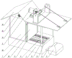
Fig. 1 is a schematic view of the overall structure of the present invention.
Fig. 2 is a schematic view of the overall internal structure of the present invention.
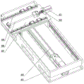
Fig. 3 is a schematic structural diagram of the moving slide table mechanism of the present invention.
Fig. 4 is a schematic view of the moving slide mechanism of the present invention.
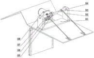
Fig. 5 is a schematic view of the traction mechanism of the lift gate of the present invention.
Fig. 6 is a schematic view of a traction mechanism of the lift gate of the present invention.
Figure 7 is a schematic view of the closable power distribution frame mechanism of the present invention.
1-a power distribution cabinet base; 2-a water collecting tank; 3-a water collecting pipeline; 4-moving the sliding table mechanism; 5-lifting door traction mechanism; 6-a closable power distribution rack; 7-distribution cabinet door; 8-a water collecting tank; 9-ceiling struts; 10-a guide rail bracket; 11-a guide wheel; 12-a front plate of a power distribution cabinet; 13-electrical switch card slot; 14-an exhaust fan; 15-a connecting plate; 16-ceiling; 17-side door upper gear; 18-left side panel; 19-a hauling rope; 20-a traction rope guide wheel; 401 — a slide table side plate; 402-single axis sliding robot; 403-sliding connection base; 404-a connection station; 405-a lateral guide bracket; 406-a guide rail; 407-X axis motion stage; 408-a screw; 409-linear bearing seat; 410-a coupler; 411-a movement drive motor; 501-a tractor fixing plate; 502-shaft support; 503-a reel; 504-a drive shaft; 505-synchronous toothed belt; 506-synchronous toothed belt wheel; 507-a connecting shaft; 508-a drive motor; 509-worm; 510-a turbine; 601-a backplane; 602-a moving track; 603-a stepper motor; 604-a wheel support; 605-long drive link; 606-a turntable; 607-front and rear carrier links; 608-a rotating shaft; 609-incoming line plug; 610-appliance switch socket; 611-incoming line connection board.
Detailed Description
The present invention will be further described with reference to specific examples, which are illustrative of the invention and are not to be construed as limiting the invention.
Example (b): a power distribution cabinet convenient for maintenance comprises a power distribution cabinet base 1, a water collection tank 2, a water collection pipeline 3, a water collection tank 8, a ceiling support 9, a power distribution cabinet front plate 12, an exhaust fan 14, a connecting plate 15, a ceiling 16 and a left side panel 18, wherein the lower part of the power distribution cabinet base 1 is fixedly connected with a ground foundation, the water collection tank 2 is fixedly connected with the right side of the power distribution cabinet through the water collection pipeline 3, the water collection tank 8 is positioned in the middle of the power distribution cabinet base 1 and is communicated with the peripheral bottom, the bottom is connected with the left side of the water collection pipeline 3, the ceiling support 9 is arranged on the right side of the upper part of the power distribution cabinet base 1 and is supported on the ceiling 16 above, the power distribution cabinet front plate 12 is symmetrically arranged at the left side of the upper part of the power distribution cabinet base 1 in the front-back direction, the exhaust fan 14 is positioned in, the left panel 18 is arranged on the leftmost side of the power distribution cabinet base 1 and is fixedly connected with the front panel 12 of the front and rear power distribution cabinets.
A power distribution cabinet convenient for maintenance further comprises a movable sliding table mechanism 4, a lifting door traction mechanism 5, a closable power distribution frame 6, a power distribution cabinet door 7, a guide rail frame 10, a guide wheel 11, an electric switch clamping groove 13, a side door upper baffle 17, a traction rope 19 and a traction rope guide wheel 20, wherein the movable sliding table mechanism 4 is arranged in the power distribution cabinet base 1, the upper side of the movable sliding table mechanism 4 is exposed, a water collecting groove 8 is formed around the movable sliding table mechanism 4, the lifting door traction mechanism 5 is arranged in the middle position of the left side of the upper surface of a ceiling 16, the closable power distribution frame 6 is arranged on the movable sliding table mechanism 4, the closable power distribution frame 6 can move along the X-axis direction and the Y-axis direction through the movement of the movable sliding table mechanism 4, the power distribution cabinet door 7 is arranged on the right side of a front plate 12 of the power distribution cabinet, the guide wheel 11 is fixed, the electric switch clamping groove 13 can be installed in the front of the closable power distribution frame 6 as required, the side door upper baffle 17 is installed on the upper portion of the right side of the front plate 12 of the power distribution cabinet, one end of the traction rope 19 is connected with the lifting door traction mechanism 5, the other end of the traction rope is connected and fixed on the power distribution cabinet door 7, the traction rope guide wheel 20 fixed on the right side of the ceiling 16 is wound in the middle of the traction rope 19, and the lifting door traction mechanism 5 drives the traction rope 19 to move when moving to lift the power distribution cabinet door 7 along the guide rail frame 10.
The movable sliding table mechanism 4 comprises a sliding table side plate 401, a single-shaft sliding robot 402, an X-axis movable platform 407, a screw 408, a linear bearing seat 409, a coupler 410 and a movable driving motor 411, and further comprises a sliding connection seat 403, a connection table 404, a side guide support 405 and guide slide rails 406, wherein the middle of the sliding table side plate 401 is hollowed out and fixed on the periphery to form a peripheral frame, the single-shaft sliding robot 402 is arranged at the middle position of the bottom and can move in the Y-axis direction, the sliding connection seat 403 is arranged on the single-shaft sliding robot 402, when the single-shaft sliding robot 402 moves along the Y-axis, the sliding connection seat 403 is driven to move together, the lower part of the connection table 404 is arranged and fixed on the sliding connection seat 403, the upper part of the connection table is arranged and fixed with the X-axis movable platform 407, the side guide support 405 is symmetrically arranged on the guide slide rails 406 on the, the guide sliding rail 406 provides a supporting function for the side guide bracket 405, the screw 408 is installed in the middle of the X-axis moving platform 407, the moving driving motor 411 is connected with the moving driving motor 411 through the coupler 410 to provide a rotating motion for the screw 408, and the linear bearing seats 409 are symmetrically installed on two sides of the X-axis moving platform 407 and used for fixing and moving the closable power distribution frame 6.
The uniaxial slip robot 402 drives the slip connecting seat 403 to move along the Y axis, the connecting table 404 drives the fixed X-axis moving platform 407 to move together under the driving of the slip connecting seat 403, the moving driving motor 411 is connected with the screw 408 through the coupler 410, so that the screw 408 performs rotary motion, the base of the closable power distribution frame 6 forms spiral fit on the screw 408, and the rotation of the screw 408 brings the closable power distribution frame 6 to move back and forth.
The lifting door traction mechanism 5 comprises a tractor fixing plate 501, a shaft bracket 502, a reel 503, a transmission shaft 504 and a driving motor 508, the lifting door traction mechanism 5 further comprises a synchronous cog belt 505, a synchronous cog belt wheel 506, a connecting shaft 507, a worm 509 and a worm wheel 510, the tractor fixing plate 501 is arranged above the ceiling 16 and used for supporting and fixing the shaft bracket 502, the shaft bracket 502 is arranged on two sides of the tractor fixing plate 501 and symmetrically distributed, the reel 503 is arranged on two sides of the transmission shaft 504 and fixed on the shaft bracket 502, the synchronous cog belt wheel 506 is arranged on the middle part of the transmission shaft 504 close to the left, the synchronous cog belt 505 is arranged on the synchronous cog belt wheel 506, the drive shaft 504 and the connecting shaft 507 are connected by a timing belt 505, a worm 509 is mounted on a drive motor 508, the worm 509 and a worm wheel 510 are brought into gear engagement, and the worm wheel 510 is fixed to the connecting shaft 507 so that the worm wheel 510 and the connecting shaft 507 rotate together.
The driving motor 508 is connected with the worm 509 to drive the worm 509 to rotate, the worm 509 is meshed with the worm wheel 510 to drive the worm wheel 510 to rotate, the worm wheel 510 drives the connecting shaft 507 to rotate, the connecting shaft 507 drives the synchronous toothed belt wheel 506 to rotate through the synchronous toothed belt 505, meanwhile, the driving shaft 504 is driven to rotate, the driving shaft 504 is fixedly connected with the winding wheel 503, and the winding wheel 503 winds up the traction rope 19 to drive the power distribution cabinet door 7 to ascend and descend.
The closable power distribution frame 6 comprises a bottom plate 601, a moving track 602 and a stepping motor 603, the closable power distribution frame 6 further comprises a rotating wheel support 604, a long transmission connecting rod 605, a rotating disc 606, front and rear frame connecting rods 607, a rotating shaft 608, an incoming line plug 609, an electrical switch socket 610 and an incoming line connecting plate 611, the bottom plate 601 is arranged on a linear bearing seat 409, so that the whole closable power distribution frame 6 can move under the driving of the linear bearing seat 409, the left and right sides of the moving track 602 are respectively arranged above the bottom plate 601, the stepping motor 603 is fixed on the rotating wheel support 604, the rotating wheel support 604 is used for fixedly supporting an upper rotating disc 606 and a lower rotating disc 606, the rotating disc 606 is directly provided with the long transmission connecting rod 605 at the same radius position, the front and rear frame connecting rods 607 fixed through the rotating shaft 608 are arranged at the upper and lower positions of the rotating disc 606 above the rotating wheel support 604, the front and rear, the incoming line plug 609 is in contact with the electric switch socket 610 in a rotating fit mode, the electric switch socket 610 is fixed on the incoming line connecting plate 611 of the station, and the incoming line plug 609 is in contact with or separated from the electric switch socket 610 through rotation of the rotating disc 606, so that on-off of the whole circuit is controlled.
The upper and lower turntables 606 complete the pivoting by the long transmission connecting rod 605 under the driving of the stepping motor 603, and the front and rear frame connecting rods 607 at the upper and lower two positions of the upper turntables 606 move forward and backward, so that the electrical switch socket 610 and the ceiling strut 9 of the guide rail frame 10 are contacted or disconnected, and the on-off control of the whole circuit is completed.