CN111060552B - Device and method for testing one-dimensional heat exchange phase change process of waxy phase change material - Google Patents

Device and method for testing one-dimensional heat exchange phase change process of waxy phase change material Download PDF

Info

Publication number
CN111060552B
CN111060552B CN201911385363.0A CN201911385363A CN111060552B CN 111060552 B CN111060552 B CN 111060552B CN 201911385363 A CN201911385363 A CN 201911385363A CN 111060552 B CN111060552 B CN 111060552B
Authority
CN
China
Prior art keywords
tank
phase change
water
change material
temperature
Prior art date
Legal status (The legal status is an assumption and is not a legal conclusion. Google has not performed a legal analysis and makes no representation as to the accuracy of the status listed.)
Active
Application number
CN201911385363.0A
Other languages
Chinese (zh)
Other versions
CN111060552A (en
Inventor
杨亚楠
刘崇义
王树新
张宏伟
Current Assignee (The listed assignees may be inaccurate. Google has not performed a legal analysis and makes no representation or warranty as to the accuracy of the list.)
Tianjin University
Original Assignee
Tianjin University
Priority date (The priority date is an assumption and is not a legal conclusion. Google has not performed a legal analysis and makes no representation as to the accuracy of the date listed.)
Filing date
Publication date
Application filed by Tianjin University filed Critical Tianjin University
Priority to CN201911385363.0A priority Critical patent/CN111060552B/en
Publication of CN111060552A publication Critical patent/CN111060552A/en
Application granted granted Critical
Publication of CN111060552B publication Critical patent/CN111060552B/en
Active legal-status Critical Current
Anticipated expiration legal-status Critical

Links

Images

Classifications

    • GPHYSICS
    • G01MEASURING; TESTING
    • G01NINVESTIGATING OR ANALYSING MATERIALS BY DETERMINING THEIR CHEMICAL OR PHYSICAL PROPERTIES
    • G01N25/00Investigating or analyzing materials by the use of thermal means
    • G01N25/02Investigating or analyzing materials by the use of thermal means by investigating changes of state or changes of phase; by investigating sintering
    • FMECHANICAL ENGINEERING; LIGHTING; HEATING; WEAPONS; BLASTING
    • F15FLUID-PRESSURE ACTUATORS; HYDRAULICS OR PNEUMATICS IN GENERAL
    • F15BSYSTEMS ACTING BY MEANS OF FLUIDS IN GENERAL; FLUID-PRESSURE ACTUATORS, e.g. SERVOMOTORS; DETAILS OF FLUID-PRESSURE SYSTEMS, NOT OTHERWISE PROVIDED FOR
    • F15B1/00Installations or systems with accumulators; Supply reservoir or sump assemblies
    • F15B1/26Supply reservoir or sump assemblies
    • FMECHANICAL ENGINEERING; LIGHTING; HEATING; WEAPONS; BLASTING
    • F15FLUID-PRESSURE ACTUATORS; HYDRAULICS OR PNEUMATICS IN GENERAL
    • F15BSYSTEMS ACTING BY MEANS OF FLUIDS IN GENERAL; FLUID-PRESSURE ACTUATORS, e.g. SERVOMOTORS; DETAILS OF FLUID-PRESSURE SYSTEMS, NOT OTHERWISE PROVIDED FOR
    • F15B11/00Servomotor systems without provision for follow-up action; Circuits therefor
    • FMECHANICAL ENGINEERING; LIGHTING; HEATING; WEAPONS; BLASTING
    • F15FLUID-PRESSURE ACTUATORS; HYDRAULICS OR PNEUMATICS IN GENERAL
    • F15BSYSTEMS ACTING BY MEANS OF FLUIDS IN GENERAL; FLUID-PRESSURE ACTUATORS, e.g. SERVOMOTORS; DETAILS OF FLUID-PRESSURE SYSTEMS, NOT OTHERWISE PROVIDED FOR
    • F15B19/00Testing; Calibrating; Fault detection or monitoring; Simulation or modelling of fluid-pressure systems or apparatus not otherwise provided for
    • F15B19/005Fault detection or monitoring

Landscapes

  • Engineering & Computer Science (AREA)
  • Physics & Mathematics (AREA)
  • General Engineering & Computer Science (AREA)
  • Mechanical Engineering (AREA)
  • Fluid Mechanics (AREA)
  • General Health & Medical Sciences (AREA)
  • Biochemistry (AREA)
  • General Physics & Mathematics (AREA)
  • Immunology (AREA)
  • Pathology (AREA)
  • Analytical Chemistry (AREA)
  • Chemical & Material Sciences (AREA)
  • Life Sciences & Earth Sciences (AREA)
  • Health & Medical Sciences (AREA)
  • Testing Resistance To Weather, Investigating Materials By Mechanical Methods (AREA)

Abstract

本发明公开一种蜡质类相变材料一维热交换相变过程测试装置及方法,装置包括液压系统、上水池、下水池、密封罐四部分。液压系统包括油箱、液位传感器、液压泵、驱动电机、单向阀、调压阀、截止手阀、压力传感器、橡胶皮囊;上水池包括上水槽、上冷热交换机、上温度传感器;下水池包括下水槽、下冷热交换机、下温度传感器;密封罐包括导热上盖、导热下盖、陶瓷管壁、螺栓、流体入口单向阀、流体出口单向阀、流体入口堵头、流体出口堵头。本发明装置具备在多种温度、压力条件下开展相变材料、相变材料与增强导热纳米粉末混合物的一维热交换相变过程测试及材料性能评估,具有测量精准、连续采集、自动化程度高、通用性强等优点。

Figure 201911385363

The invention discloses a one-dimensional heat exchange phase change process testing device and method of a wax-like phase change material. The device comprises four parts: a hydraulic system, an upper pool, a lower pool and a sealing tank. Hydraulic system includes fuel tank, liquid level sensor, hydraulic pump, drive motor, one-way valve, pressure regulating valve, stop valve, pressure sensor, rubber bladder; upper water tank includes upper water tank, upper cooling and heat exchanger, upper temperature sensor; lower water tank Including the lower water tank, the lower heat exchanger, the lower temperature sensor; the sealed tank includes the heat conduction upper cover, the heat conduction lower cover, the ceramic tube wall, the bolt, the fluid inlet check valve, the fluid outlet check valve, the fluid inlet plug, the fluid outlet plug head. The device of the invention can carry out the one-dimensional heat exchange phase change process test and material performance evaluation of the phase change material, the phase change material and the thermally enhanced nano-powder mixture under various temperature and pressure conditions, and has the advantages of accurate measurement, continuous acquisition and high degree of automation. , strong versatility and so on.

Figure 201911385363

Description

Device and method for testing one-dimensional heat exchange phase change process of waxy phase change material
Technical Field
The invention belongs to the technical field of phase change driving, and particularly relates to a device and a method for testing a one-dimensional heat exchange phase change process of a waxy phase change material.
Background
The phase change driving is a driving mode for realizing external work by using volume change generated in a solid-liquid phase change process of a material, wherein the phase change material is the key for realizing the phase change driving, and the phase change material is converted from a solid phase to a liquid phase after absorbing enough heat near a phase change temperature point and realizes volume expansion, or is converted from the liquid phase to the solid phase after releasing enough heat and realizes volume reduction. The phase change driving can be completed only by depending on the change of the environmental temperature without an additional power supply or a control unit, so that the electric energy is saved, and the phase change driving device has the characteristic of large output driving force.
Phase change materials can be broadly classified according to their physical and chemical properties into: waxes, acetates, hydrated salts, molten salts, metals or alloys, and the like. Among various phase change materials, the waxy phase change material has the advantages of wide phase change temperature selectable range, high phase change latent heat, no toxicity, no corrosiveness, relatively stable physicochemical properties and the like, and is a phase change material which is preferably selected in the fields of aerospace, oceans and medical treatment. For phase change driving, the volume change rate of a phase change material is a primary performance evaluation index, and in addition, the heat conduction capability of the material is improved by adding enhanced heat conduction nano powder into the phase change material, so that the volume change rate and the heat conduction capability test of a mixture of the phase change material, the phase change material and the enhanced heat conduction nano powder are necessary, and data reference can be provided for the design of a phase change driving device.
Most of the existing phase-change material testing devices adopt ways such as an Archimedes principle measuring method, a displacement liquid observation method, a gas pressure indirect measuring method and the like, and the methods have a plurality of defects, and 1, the influence of the pressure condition in the phase-change process on the volume change rate and the heat conduction capability of the phase-change is not considered; 2. the human eye observation recorded data has low precision and cannot record data continuously in real time; 3. the thermal interference factors are many, the phase change material cannot realize an ideal one-dimensional heat exchange phase change process, and the accuracy of the test is influenced.
Disclosure of Invention
The invention aims to overcome the defects in the prior art, and provides a device and a method for testing the one-dimensional heat exchange phase change process of a wax phase change material, which are capable of carrying out the one-dimensional heat exchange phase change process test and material performance evaluation of the mixture of the phase change material, the phase change material and the enhanced heat conduction nanometer powder under various temperature and pressure conditions. The method has the advantages of accurate measurement, continuous acquisition, high automation degree, strong universality and the like.
The purpose of the invention is realized by the following technical scheme:
a one-dimensional heat exchange phase change process testing device for wax phase change materials comprises a hydraulic system, an upper water tank, a lower water tank and a sealing tank, wherein the hydraulic system comprises an oil tank, a liquid level sensor, a hydraulic pump, a driving motor, a one-way valve, a pressure regulating valve, a stop hand valve, a pressure sensor and a rubber bag; the upper water tank comprises an upper water tank, an upper cold-heat exchanger and an upper temperature sensor; the lower water tank comprises a lower water tank, a lower cold-heat exchanger and a lower temperature sensor; the sealing tank comprises a heat-conducting upper cover, a heat-conducting lower cover, a ceramic pipe wall, a bolt, a fluid inlet one-way valve, a fluid outlet one-way valve, a fluid inlet plug and a fluid outlet plug;
an oil tank of the hydraulic system is connected with an inlet oil path of a hydraulic pump, an outlet oil path of the hydraulic pump is connected with an inlet of a one-way valve, an outlet of the one-way valve is divided into two branches which are respectively connected with an inlet of a pressure regulating valve and an inlet of a stop hand valve, an outlet oil path of the pressure regulating valve returns to the oil tank, and an outlet oil path of the stop hand valve is sequentially connected with a pressure sensor and a rubber bag;
the water feeding tank of the water feeding tank is filled with water, the water temperature in the water feeding tank is monitored by the upper temperature sensor, the upper cold-hot exchanger carries out water temperature compensation in real time according to water temperature data acquired by the upper temperature sensor, and the water temperature in the water feeding tank is kept to be a set target temperature value T1
The lower water tank of the lower water tank is filled with water, the lower temperature sensor monitors the temperature of the water in the lower water tank, the lower cold-hot exchanger carries out water temperature compensation in real time according to water temperature data acquired by the lower temperature sensor, and the water temperature in the lower water tank is kept to be a set target temperature value T2
The heat-conducting upper cover, the heat-conducting lower cover and the ceramic pipe wall of the sealed tank form a pressure-bearing sealed cavity. And water, a phase-change material, a rubber leather bag and hydraulic oil are arranged in the pressure-bearing sealing cavity of the sealing tank. In the sealed tank, the phase-change material floats on the water, and a liquid interface exists between the phase-change material and the water. The contact surface of the heat-conducting upper cover and the phase-change material is an upper heat-conducting interface, and the contact surface of the heat-conducting lower cover and the water is a lower heat-conducting interface. The rubber leather bag is completely immersed in water, and the hydraulic oil and the water are physically isolated by the rubber leather bag.
Furthermore, the upper water pool is arranged at the top of the sealing tank, and the bottom of the upper water tank is in contact with the top end face of the heat-conducting upper cover. The oil tank and the seal tank are arranged in the lower water pool. The upper water tank exchanges heat with the heat-conducting upper cover, and the lower water tank exchanges heat with the heat-conducting lower cover and the oil tank.
Furthermore, the rubber leather bag is arranged at the rotary axis of the heat-conducting lower cover and is arranged in the sealing tank. Hydraulic oil is filled in the hydraulic system and the rubber bag. The driving motor drives the hydraulic pump to operate, the one-way valve prevents hydraulic oil from reversely flowing back to the hydraulic pump, and the pressure regulating valve can regulate and keep the oil filling pressure of the rubber bladder at a set value p0And the stop hand valve can close the rubber bag to keep the volume of the hydraulic oil in the rubber bag constant. Pressure sensor capable of monitoring oil filling pressure p of rubber bladder0
Furthermore, the liquid level of the oil tank floats along with the volume change of hydraulic oil filled in the rubber bag. The oil tank is a uniform-section oil tank, and the cross-sectional area of the oil tank is S. The liquid level sensor is used for detecting the height value h of the liquid level of the oil tank. The change value delta V of the oil-filled volume of the rubber bag can be calculated as S.delta h.
Furthermore, the phase-change material has a phase-change temperature of 0-100 ℃ and a density of less than 1g/cm-3And the waxy material is insoluble in water, wherein the waxy material is composed of one or more of paraffin material, n-heptadecane, n-hexadecane, n-pentadecane and n-tetradecane.
Furthermore, the heat-conducting upper cover and the heat-conducting lower cover are of rotary stepped cylindrical structures, grooves are designed on the circumferential surfaces of the heat-conducting upper cover and the heat-conducting lower cover, and the sealing rings in the grooves realize radial sealing of the pressure-bearing sealing cavity. Bolt mounting holes are uniformly distributed on the periphery of the edge of the end face of the heat-conducting upper cover and the heat-conducting lower cover, and the heat-conducting upper cover and the heat-conducting lower cover are tightly and fixedly connected with the wall of the ceramic tube by bolts.
Further, the heat conduction lower cover is provided with a fluid inlet and a fluid outlet. Water and phase-change materials are injected into the sealing tank through the fluid inlet, and simultaneously air in the sealing tank is discharged through the fluid outlet in the process of injecting water and phase-change material liquid into the sealing tank. A fluid inlet single valve is installed in the fluid inlet, and a fluid outlet single valve is installed in the fluid outlet. The fluid inlet single-way valve and the fluid outlet single-way valve are used for keeping the fluid to flow in a single direction. The fluid inlet plug is arranged on the end face of the heat-conducting lower cover to seal the fluid inlet, and the fluid outlet plug is arranged on the end face of the heat-conducting lower cover to seal the fluid outlet.
Furthermore, the ceramic pipe wall is a circular pipe structure made of heat insulation ceramic, and the rotation axis of the ceramic pipe wall is arranged along the vertical direction, so that the heat dissipation or the heat absorption of the sealed tank along the circumferential direction can be avoided. The phase-change material generates heat exchange with the outside at an upper heat conduction interface and a liquid interface, and the heat exchange process is a one-dimensional process only carried out along the vertical rotation axis direction of the seal tank.
Furthermore, the testing device for the one-dimensional heat exchange phase change process of the waxy phase change material is used for testing in a thermostatic chamber, and the temperature of water in the thermostatic chamber and the temperature of water in a lower water pool are kept consistent and are T2
Furthermore, the testing temperature condition T of the testing device for the one-dimensional heat exchange phase change process of the waxy phase change material0、T1、T2Satisfy the relation T1<T0<T2
Further, the liquid volume V of the phase change material in the sealed tank0Much less than the volume of water, the volume V of the phase change material liquid0Is the nominal volume V of the rubber bladder150% of the total.
A test method for one-dimensional heat exchange phase change process of waxy phase change material comprises the following steps:
s1: the rotary axis of the cylinder of the sealing tank is placed along the vertical direction, and the heat-conducting lower cover is positioned above the heat-conducting upper cover. And unscrewing the fluid inlet plug and the fluid outlet plug, injecting water into the inner cavity of the sealed tank through the fluid inlet, discharging air in the inner cavity of the sealed tank through the fluid outlet, and discharging air in the rubber bag through the rubber bag interface. When the water continuously flows out of the fluid outlet, the air in the inner cavity of the seal pot and the rubber bag is completely discharged, the inner cavity of the seal pot is filled with the water, the rubber bag is crushed, and the fluid inlet plug and the fluid outlet plug are screwed down.
S2: after the water injection of the seal tank is completed, the rubber bag is connected with a hydraulic system, the stop hand valve and the pressure sensor are opened, the pressure regulating valve is adjusted to enable the pressure of an oil path to be in a zero state, the driving motor is started and the hydraulic pump is driven to continuously run, hydraulic oil is gradually circulated into a pipeline of the hydraulic system from the oil tank, and residual air in the pipeline is discharged from an outlet of the pressure regulating valve. When the outlet of the pressure regulating valve continuously flows out hydraulic oil, and the liquid level sensor detects that the liquid level height value h of the oil tank is kept constant, the fact that air in the hydraulic system is completely discharged and filled with the hydraulic oil is indicated, and then the driving motor, the stop hand valve and the pressure sensor are closed.
S3: the sealed tank keeps the cylinder rotation axis to be placed along the vertical direction, and the heat conduction upper cover is located above the heat conduction lower cover. Unscrewing the fluid inlet plug and the fluid outlet plug, and injecting the fluid into the inner cavity of the sealed tank through the fluid inlet with the volume V0The phase change material liquid of (2). The phase-change material is lower than water and insoluble in water due to density, after entering the inner cavity, the phase-change material floats on the upper layer of the water, and in the process of injecting the phase-change material, the sealing tank discharges the same volume V through the fluid outlet0The fluid inlet and outlet plugs are then tightened.
S4: the sealed tank keeps the cylinder rotation axis to be placed along the vertical direction, and the heat conduction upper cover is located above the heat conduction lower cover. Starting the stop hand valve and the pressure sensor, starting the driving motor and driving the hydraulic pump to continuously operate, and adjusting the pressure regulating valve to make the oil charging pressure of the rubber bladder be p0Unscrewing a fluid outlet plug, injecting hydraulic oil into the rubber leather bag by a hydraulic system, wherein the injection volume is the nominal volume V of the rubber leather bag150% of the total amount of the components, and simultaneously discharging 50% V from the sealed tank through a fluid outlet1The volume of water is then screwed down to close the fluid outlet plug, the stop hand valve, the pressure sensor, and the drive motor.
S5: the ambient temperature in the thermostatic chamber is regulated to T2The storage temperature in the lower water tank is T2The water tank is filled with the sealing tank filled with the phase-change materials and the oil tank, the cylinder rotation axis is kept to be placed along the vertical direction, and the heat-conducting upper cover of the sealing tank is positioned above the heat-conducting lower cover. Opening the stop hand valve and the pressure sensor, starting the driving motor and driving the hydraulic pump to continuously operate, and adjusting the pressure regulating valve to the inflation of the rubber bagOil pressure p0. The sealed tank and the oil tank are kept stand in the water tank for a long time until the liquid level height of the oil tank detected by the liquid level sensor is constant h, and the temperatures of hydraulic oil, water and phase-change materials are all T2The equilibrium state of (1).
S6: the temperature of the upper water pool is T1The water of (2). The temperature of hydraulic oil, water and phase-change material is T2And then, starting the test, and placing the upper water pool on the top of the heat-conducting upper cover.
S7: at a temperature T1<T0<T2Under the condition, under the action of the temperature difference between the upper water tank and the lower water tank, the heat-conducting interface, the phase-change material and the liquid interface generate heat exchange along the axis direction, the phase-change material gradually generates one-dimensional phase change from liquid to solid from the upper heat-conducting interface and along the vertical axis downwards, the volume of the phase-change material gradually shrinks, the height of the liquid interface gradually rises, the rubber leather bag gradually expands, hydraulic oil is supplemented into the rubber leather bag, the height of the liquid level of the oil tank drops, the liquid level sensor continuously collects the change process of the height h of the liquid level of the oil tank, and the height change quantity delta h curve of the liquid level is recorded. And when the phase change material and the water reach the equilibrium state again, the liquid level h of the oil tank stops changing.
S8: by repeating the above-mentioned operations S1-S7, the present invention can be used at various pressures p0Under the condition of and T1、T2And carrying out comparison tests on different phase-change materials under the condition of a temperature boundary.
S9: rate of change of volume of phase change material to be at pressure p0Temperature T1And T2Under the condition, after carrying out the heat exchange test of the time length t, calculating S.DELTA.h.V0 -1The value is evaluated, and the heat conductivity of the phase change material is evaluated according to the time point t0The rate of change of the liquid level h dh/dt0Evaluation was performed.
Compared with the prior art, the technical scheme of the invention has the following beneficial effects:
1. the invention realizes the square sealing of the phase-change material on the top of the inner cavity of the sealed tank and floating on the water by utilizing the incompatibility and different densities of the water and the phase-change material. The soft characteristic of the rubber bag is utilized to realize the physical isolation of the hydraulic oil and the water. The liquid interface between water and phase-change material moves in vertical direction along with phase-change process, and the rubber bag changes shape along with the change of oil-filled volume, and has no friction resistance loss.
2. The phase change material is filled by water, and the phase change material is in close contact with water on a liquid interface without additional contact thermal resistance; the oil charging pressure applied by the hydraulic system helps to improve the contact tightness between the phase change material and the upper heat conducting cover at the upper heat conducting interface.
3. In the testing process, the liquid level height change value of the oil tank is measured only by collecting the data of the liquid level sensor, so that the volume change data of the phase change material in the phase change process can be indirectly obtained, and the method has high automation degree and strong data continuity.
4. The ceramic pipe wall avoids circumferential heat exchange, the upper water pool and the lower water pool which are used as heat sources and cold sources, the heat conduction upper cover and the heat conduction lower cover, the phase-change material and water are arranged in the vertical direction, the heat exchange of the device is carried out along the direction of a vertical rotation axis, the phase-change material is subjected to a phase-change process in the device in an ideal one-dimensional heat exchange mode, and the comparative evaluation of the heat conduction capacity and the volume change rate of different phase-change materials is facilitated.
5. The invention can set various constant temperature difference conditions through the upper water pool and the lower water pool, and can set various phase change pressure conditions through the hydraulic system, thereby realizing the test under various temperature and pressure conditions.
6. The device has the advantages of simple structure, easy realization, low manufacturing cost and strong universality, and is suitable for various waxy phase-change materials and mixtures thereof.
Drawings
FIG. 1 is a schematic diagram of the structure and principle of the present invention;
Detailed Description
The invention is described in further detail below with reference to the figures and specific examples. It should be understood that the specific embodiments described herein are merely illustrative of the invention and are not intended to limit the invention.
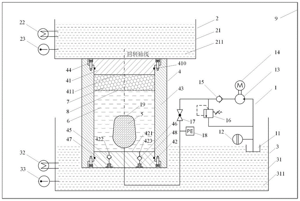
As shown in fig. 1, a testing device for one-dimensional heat exchange phase change process of wax phase change material comprises four parts of a hydraulic system 1, an upper water pool 2, a lower water pool 3 and a seal tank 4, wherein the hydraulic system 1 comprises an oil tank 11, a liquid level sensor 12, a hydraulic pump 13, a driving motor 14, a one-way valve 15, a pressure regulating valve 16, a stop hand valve 17, a pressure sensor 18 and a rubber bag 19; the upper water pool 2 comprises an upper water tank 21, an upper cold and heat exchanger 22 and an upper temperature sensor 23; the lower water tank 3 comprises a lower water tank 31, a lower heat exchanger 32 and a lower temperature sensor 33; the sealed tank 4 comprises a heat-conducting upper cover 41, a heat-conducting lower cover 42, a ceramic pipe wall 43, a bolt 44, a fluid inlet check valve 45, a fluid outlet check valve 46, a fluid inlet plug 47 and a fluid outlet plug 48.
An oil tank 11 of the hydraulic system 1 is connected with an inlet oil path of a hydraulic pump 13, an outlet oil path of the hydraulic pump 13 is connected with an inlet of a one-way valve 15, an outlet of the one-way valve 15 is divided into two branches which are respectively connected with an inlet of a pressure regulating valve 16 and an inlet of a stop hand valve 17, an outlet oil path of the pressure regulating valve 16 returns to the oil tank 11, and an outlet oil path of the stop hand valve 17 is sequentially connected with a pressure sensor 18 and a rubber bag 19. The rubber bag 19 is arranged at the rotation axis of the heat-conducting lower cover 42 and is arranged in the sealing tank 4. The hydraulic system 1 and the rubber bag 19 are filled with hydraulic oil 5. The driving motor 14 drives the hydraulic pump 13 to operate, the one-way valve 15 prevents the hydraulic oil 5 from reversely flowing back to the hydraulic pump 13, and the pressure regulating valve 16 can regulate and keep the oil filling pressure of the rubber bag 19 at a set value p0The stop hand valve 17 can close the rubber bladder 19 to keep the volume of the hydraulic oil 5 in the rubber bladder 19 constant. The pressure sensor 18 can monitor the oil filling pressure p of the rubber bag 190
The water 211 is filled in the upper water tank 21 of the upper water tank 2, the upper temperature sensor 23 monitors the temperature of the water 211 in the upper water tank 21, the upper cold and hot exchanger 22 carries out real-time water temperature compensation according to the water temperature data acquired by the upper temperature sensor 23, and the water temperature in the upper water tank 21 is kept to be a set target temperature value T1. The lower water tank 31 of the lower water tank 3 is filled with water 311, the lower temperature sensor 33 monitors the temperature of the water 311 in the lower water tank 31, and the lower heat exchanger 32 performs real-time water temperature compensation according to the water temperature data acquired by the lower temperature sensor 33 to keep the water temperature in the lower water tank 31 at the set target temperature value T2
The heat-conducting upper cover 41, the heat-conducting lower cover 42 and the ceramic pipe wall 43 of the sealed tank 4 form a pressure-bearing sealed cavity, the ceramic pipe wall 43 is of a circular pipe structure, the rotation axis of the ceramic pipe wall is arranged along the vertical direction, the heat-conducting upper cover 41 and the heat-conducting lower cover 42 are of a rotary stepped cylindrical structure, grooves are designed on the circumferential surface of the heat-conducting upper cover and the heat-conducting lower cover, and the sealing rings 410 in the grooves realize radial sealing of the pressure-bearing sealed cavity. The heat-conducting upper cover 41 and the heat-conducting lower cover 42 are evenly provided with bolt mounting holes on the circumference of the edge of the end face and are fixedly connected with the ceramic pipe wall 43 by bolts 44.
The pressure-bearing sealed cavity of the sealed tank 4 is internally provided with water 6, a phase-change material 7, a rubber bag 19 and hydraulic oil 5. Inside the sealed tank 4, the phase change material 7 floats on top of the water 6, and the phase change material 7 and the water 6 have a liquid interface 8. The contact surface of the upper heat-conducting cover 41 and the phase-change material 7 is an upper heat-conducting interface 411, and the contact surface of the lower heat-conducting cover 42 and the water 6 is a lower heat-conducting interface 421. The rubber bladder 19 is completely immersed in the water 6, and the hydraulic oil 5 is physically separated from the water 6 by the rubber bladder 19.
Preferably, the phase-change material 7 has a phase-change temperature of 0-100 deg.C and a density of less than 1g/cm-3And water insoluble waxy materials. Wherein the waxy material is composed of one or more of paraffin wax material, n-heptadecane, n-hexadecane, n-pentadecane and n-tetradecane.
Preferably, the upper water tank 2 is arranged on the top of the sealed tank 4, and the bottom of the upper water tank 21 is in contact with the top end face of the heat-conducting upper cover 41. The oil tank 11 and the seal tank 4 are placed in the lower water tank 3. The upper water tank 2 exchanges heat with the heat-conducting upper cover 41, and the lower water tank 3 exchanges heat with the heat-conducting lower cover 42 and the oil tank 11.
Preferably, the ceramic pipe wall 43 is made of heat-insulating ceramic, so as to prevent the sealed tank 4 from radiating or absorbing heat along the circumferential direction. The phase-change material 7 generates heat exchange with the outside at the upper heat conducting interface 411 and the liquid interface 8, and the heat exchange process is a one-dimensional process only along the vertical rotation axis direction of the seal tank 4.
Preferably, the liquid level of the oil tank 11 is floated according to the volume change of the hydraulic oil 5 filled in the rubber bag 19. The tank 11 is a constant-section tank having a cross-sectional area S. The liquid level sensor 12 is used for detecting the liquid level height value h of the oil tank 11. The change value DeltaV of the oil-filled volume of the rubber bag 19 can be calculated as S.Deltah.
Preferably, the thermally conductive lower cover 42 is provided with a fluid inlet 422, a fluid outlet 423. The water 6 and the phase-change material 7 are injected into the seal tank 4 through the fluid inlet 422, and simultaneously, the air in the seal tank 4 is discharged through the fluid outlet 423 in the process that the water 6 and the phase-change material 7 are injected into the seal tank 4. A fluid inlet one-way valve 45 is installed in the fluid inlet 422, and a fluid outlet one-way valve 46 is installed in the fluid outlet 423. The fluid inlet single-way valve 45 and the fluid outlet single-way valve 46 are used for keeping the fluid flowing in a single direction. The fluid inlet plug 47 is mounted to the end surface of the thermally conductive lower cover 42 to seal the fluid inlet 422, and the fluid outlet plug 48 is mounted to the end surface of the thermally conductive lower cover 42 to seal the fluid outlet 423.
Preferably, the testing device of the present invention can be used for performing a test in the thermostatic chamber 9, and the temperature of the water 311 in the thermostatic chamber 9 and the lower water pool 3 are kept consistent and are T2. Test temperature condition T of the test device of the invention0、T1、T2Satisfy the relation T1<T0<T2. Liquid volume V of phase change material 7 in sealed tank 40Much less than 6 volumes of water and 7 volumes of liquid V of phase-change material0Is a nominal volume V of the rubber bladder 19150% of the total.
The measuring method of the testing device comprises the following steps:
1. the axis of rotation of the cylinder of the sealed can 4 is placed in the vertical direction, and the heat conductive lower lid 42 is located above the heat conductive upper lid 41. The fluid inlet plug 47 and the fluid outlet plug 48 are unscrewed, water 6 is injected into the inner cavity of the sealed tank 4 through the fluid inlet 422, air in the inner cavity of the sealed tank 4 is discharged through the fluid outlet 423, and air in the rubber bag 19 is discharged through the interface of the rubber bag 19. When the fluid outlet 423 continuously flows out of the water 6, indicating that the air in the inner cavity of the sealed tank 4 and the rubber bladder 19 is completely discharged, the inner cavity of the sealed tank 4 is filled with the water 6, the rubber bladder 19 is crushed, and the fluid inlet plug 47 and the fluid outlet plug 48 are tightened.
2. After the sealed tank 4 finishes water injection, the rubber bag 19 is connected with the hydraulic system 1, the stop hand valve 17 and the pressure sensor 18 are opened, the pressure regulating valve 16 is adjusted to enable the pressure of an oil path to be in a zero state, the driving motor 14 is started and drives the hydraulic pump 13 to continuously run, the hydraulic oil 5 is gradually circulated into a pipeline of the hydraulic system 1 from the oil tank 11, and residual air in the pipeline is discharged from an outlet of the pressure regulating valve 16. When the outlet of the pressure regulating valve 16 continuously flows out of the hydraulic oil 5, and the liquid level sensor 12 detects that the liquid level height value h of the oil tank 11 is kept constant, the air in the hydraulic system 1 is completely discharged and the hydraulic oil 5 is filled, and then the driving motor 14, the stop hand valve 17 and the pressure sensor 18 are closed.
3. The sealed can 4 keeps the cylinder rotation axis placed in the vertical direction, and the heat-conductive upper lid 41 is located above the heat-conductive lower lid 42. Unscrewing the fluid inlet plug 47 and the fluid outlet plug 48, and injecting the volume V into the inner cavity of the sealed tank 4 through the fluid inlet 4220The phase change material 7 liquid. The phase-change material 7 is lower than the water 6 and insoluble in the water 6, after entering the inner cavity, the phase-change material 7 floats on the upper layer of the water 6, and in the process of injecting the phase-change material 7, the sealed tank 4 discharges the volume V with the same volume through the fluid outlet 4230Then the fluid inlet plug 47 and the fluid outlet plug 48 are tightened.
4. The sealed can 4 keeps the cylinder rotation axis placed in the vertical direction, and the heat-conductive upper lid 41 is located above the heat-conductive lower lid 42. The stop hand valve 17 and the pressure sensor 18 are opened, the driving motor 14 is started and drives the hydraulic pump 13 to continuously run, and the pressure regulating valve 16 is regulated to ensure that the oil filling pressure of the rubber bag 19 is p0The fluid outlet plug 48 is unscrewed, the hydraulic system 1 injects the hydraulic oil 5 into the rubber leather bag 19, and the injection volume is the nominal volume V of the rubber leather bag 19150% of the amount of the component (b) and at the same time, the seal pot 4 discharges 50% V through the fluid outlet 4231The volume of water 6, then the fluid outlet plug 48 is tightened, closing the shut off hand valve 17, the pressure sensor 18, the drive motor 14.
5. The ambient temperature in the thermostatic chamber is regulated to T2The temperature of the lower water tank 3 is T2The sealed tank 4 into which the phase change material 7 has been injected and the oil tank 11 are placed in the water tank 31 while keeping the axis of rotation of the cylinder in a vertical direction, and the heat-conductive upper lid 41 of the sealed tank 4 is positioned above the heat-conductive lower lid 42. The stop hand valve 17 and the pressure sensor 18 are opened, the driving motor 14 is started and drives the hydraulic pump 13 to continuously run, and the oil charging pressure from the pressure regulating valve 16 to the rubber leather bag 19 is adjusted to be p0. The seal tank 4 and the oil tank 11 are kept still in the water pool 3 for a long enough time until the liquid level of the oil tank 11 detected by the liquid level sensor 12 is constantThe value h is T, the temperatures of the hydraulic oil 5, the water 6 and the phase-change material 7 are all T2The equilibrium state of (1).
6. The temperature of the upper water pool 2 is stored as T1Of water 211. The temperature of the hydraulic oil 5, the water 6 and the phase-change material 7 is T2Thereafter, the test is started and the upper basin 2 is placed on top of the thermally conductive upper lid 41.
7. At a temperature T1<T0<T2Under the condition, under the action of the temperature difference between the upper water tank 2 and the lower water tank 3, the heat conduction interface 411, the phase-change material 7 and the liquid interface 8 generate heat exchange along the axial direction, the phase-change material 7 gradually generates one-dimensional phase change from liquid to solid from the upper heat conduction interface 411 and downwards along a vertical axis, the volume of the phase-change material 7 gradually shrinks, the height of the liquid interface 8 gradually rises, the rubber leather bag 19 gradually expands, the hydraulic oil 5 is supplemented into the rubber leather bag 19, the liquid level of the oil tank 11 drops, the liquid level sensor 12 continuously collects the change process of the liquid level h of the oil tank 11, and a liquid level change quantity delta h curve is recorded. When the phase change material 7 and the water 6 reach the equilibrium state again, the liquid level h of the oil tank 11 stops changing.
8. The above-described 1 st to 7 th working processes are repeated, and the present invention can be used at various pressures p0Under the condition of and T1、T2And carrying out comparison tests on different phase-change materials 7 under the condition of temperature boundary.
9. Rate of change of volume of phase change material to be at pressure p0Temperature T1And T2Under the condition, after carrying out the heat exchange test of the time length t, calculating S.DELTA.h.V0 -1The value is evaluated, and the heat conductivity of the phase change material is evaluated according to the time point t0The rate of change of the liquid level h dh/dt0Evaluation was performed.
The present invention is not limited to the above-described embodiments. The foregoing description of the specific embodiments is intended to describe and illustrate the technical solutions of the present invention, and the above specific embodiments are merely illustrative and not restrictive. Those skilled in the art can make many changes and modifications to the invention without departing from the spirit and scope of the invention as defined in the appended claims.

Claims (10)

1.一种蜡质类相变材料一维热交换相变过程测试装置,其特征在于,包括液压系统(1)、上水池(2)、下水池(3)和密封罐(4)四部分,所述液压系统(1)包括油箱(11)、液位传感器(12)、液压泵(13)、驱动电机(14)、单向阀(15)、调压阀(16)、截止手阀(17)、压力传感器(18)和橡胶皮囊(19);所述上水池(2)包括上水槽(21)、上冷热交换机(22)和上温度传感器(23);所述下水池(3)包括下水槽(31)、下冷热交换机(32)和下温度传感器(33);所述密封罐(4)包括导热上盖(41)、导热下盖(42)、陶瓷管壁(43)、螺栓(44)、流体入口单向阀(45)、流体出口单向阀(46)、流体入口堵头(47)和流体出口堵头(48);1. a one-dimensional heat exchange phase change process testing device for waxy phase change materials, characterized in that it comprises four parts of a hydraulic system (1), an upper pool (2), a lower pool (3) and a sealed tank (4). , the hydraulic system (1) includes a fuel tank (11), a liquid level sensor (12), a hydraulic pump (13), a drive motor (14), a one-way valve (15), a pressure regulating valve (16), and a cut-off hand valve (17), a pressure sensor (18) and a rubber bladder (19); the upper pool (2) includes an upper water tank (21), an upper heat exchanger (22) and an upper temperature sensor (23); the lower pool (2) 3) comprising a lower water tank (31), a lower heat exchanger (32) and a lower temperature sensor (33); the sealed tank (4) comprises a thermally conductive upper cover (41), a thermally conductive lower cover (42), a ceramic tube wall ( 43), bolt (44), fluid inlet check valve (45), fluid outlet check valve (46), fluid inlet plug (47) and fluid outlet plug (48); 所述液压系统(1)的油箱(11)与液压泵(13)入口油路相连,液压泵(13)出口油路与单向阀(15)进口相连,单向阀(15)出口分为两条支路,分别与调压阀(16)的进口和截止手阀(17)的进口相连,调压阀(16)的出口油路返回至油箱(11),截止手阀(17)的出口油路依次与压力传感器(18)和橡胶皮囊(19)相连,所述驱动电机(14)驱动液压泵(13)运行;The oil tank (11) of the hydraulic system (1) is connected to the inlet oil circuit of the hydraulic pump (13), the outlet oil circuit of the hydraulic pump (13) is connected to the inlet of the check valve (15), and the outlet of the check valve (15) is divided into two parts. The two branches are respectively connected to the inlet of the pressure regulating valve (16) and the inlet of the stop hand valve (17). The outlet oil circuit is connected with the pressure sensor (18) and the rubber bladder (19) in sequence, and the driving motor (14) drives the hydraulic pump (13) to operate; 所述上水池(2)的上水槽(21)内注有水,上温度传感器(23)监测上水槽(21)内水的温度,上冷热交换机(22)依据上温度传感器(23)获取的水温数据,实时进行水温补偿,保持上水槽(21)内水温为设定目标温度值T1The upper water tank (21) of the upper water tank (2) is filled with water, the upper temperature sensor (23) monitors the temperature of the water in the upper water tank (21), and the upper cold and heat exchanger (22) obtains the temperature according to the upper temperature sensor (23). According to the water temperature data, the water temperature compensation is carried out in real time, and the water temperature in the upper water tank (21) is kept as the set target temperature value T 1 ; 所述下水池(3)的下水槽(31)内注有水,下温度传感器(33)监测下水槽(31)内水的温度,下冷热交换机(32)依据下温度传感器(33)获取的水温数据,实时进行水温补偿,保持下水槽(31)内水温为设定目标温度值T2The lower water tank (31) of the lower water pool (3) is filled with water, the lower temperature sensor (33) monitors the temperature of the water in the lower water tank (31), and the lower cooling and heat exchanger (32) is obtained according to the lower temperature sensor (33) According to the water temperature data, the water temperature compensation is carried out in real time, and the water temperature in the lower water tank (31) is kept as the set target temperature value T 2 ; 所述密封罐(4)的导热上盖(41)、导热下盖(42)、陶瓷管壁(43)组成承压密封腔体;所述密封罐(4)的承压密封腔体内装有水、相变材料(7)、橡胶皮囊(19)和液压油(5);在密封罐(4)内,所述相变材料(7)浮于密封罐内的水上部,相变材料(7)与密封罐内的水存在液体分界面(8);导热上盖(41)与相变材料(7)的接触面为上导热界面(411),导热下盖(42)与密封罐内的水的接触面为下导热界面(421);所述橡胶皮囊(19)完全浸没在密封罐内的水中,液压系统(1)、橡胶皮囊(19)内填充液压油(5),所述液压油(5)与密封罐内的水由橡胶皮囊(19)物理隔离;所述油箱(11)、密封罐(4)安放在下水池(3)中;所述上水池(2)与导热上盖(41)进行热交换,所述下水池(3)与导热下盖(42)、油箱(11)进行热交换。The heat-conducting upper cover (41), the heat-conducting lower cover (42) and the ceramic tube wall (43) of the sealing tank (4) form a pressure-bearing sealing cavity; the pressure-bearing sealing cavity of the sealing tank (4) is equipped with Water, phase change material (7), rubber bladder (19) and hydraulic oil (5); in the airtight tank (4), the phase change material (7) floats on the upper part of the water in the airtight tank, and the phase change material ( 7) There is a liquid interface (8) with the water in the sealed tank; the contact surface between the thermally conductive upper cover (41) and the phase change material (7) is the upper thermally conductive interface (411), and the thermally conductive lower cover (42) is connected to the inside of the sealed tank. The contact surface of the water is the lower heat conduction interface (421); the rubber bladder (19) is completely immersed in the water in the sealed tank, and the hydraulic system (1) and the rubber bladder (19) are filled with hydraulic oil (5). The hydraulic oil (5) is physically separated from the water in the sealing tank by a rubber bladder (19); the oil tank (11) and the sealing tank (4) are placed in the lower pool (3); the upper pool (2) is connected to the heat conduction upper pool (3). The cover (41) exchanges heat, and the lower pool (3) exchanges heat with the heat conduction lower cover (42) and the oil tank (11). 2.根据权利要求1所述一种蜡质类相变材料一维热交换相变过程测试装置,其特征在于,所述上水池(2)布置于密封罐(4)顶部,上水槽(21)底部与导热上盖(41)顶部端面接触。2. The one-dimensional heat exchange phase change process testing device of a waxy phase change material according to claim 1, wherein the upper water tank (2) is arranged on the top of the sealed tank (4), and the upper water tank (21 ) bottom is in contact with the top end face of the thermally conductive upper cover (41). 3.根据权利要求1所述一种蜡质类相变材料一维热交换相变过程测试装置,其特征在于,所述橡胶皮囊(19)安装于导热下盖(42)回转轴线处并置于密封罐(4)内;单向阀(15)用于防止液压油(5)反向回流至液压泵(13),调压阀(16)用于调节并保持橡胶皮囊(19)的充油压力为设定值p0,截止手阀(17)用于关断橡胶皮囊(19)以保持橡胶皮囊(19)内的液压油(5)体积恒定;压力传感器(18)用于监测橡胶皮囊(19)的充油压力p03 . The one-dimensional heat exchange phase change process testing device of a waxy phase change material according to claim 1 , wherein the rubber bladder ( 19 ) is installed at the rotation axis of the heat conduction lower cover ( 42 ) and juxtaposed. 4 . In the sealed tank (4); the check valve (15) is used to prevent the hydraulic oil (5) from backflowing to the hydraulic pump (13), and the pressure regulating valve (16) is used to adjust and maintain the filling of the rubber bladder (19). The oil pressure is the set value p 0 , the cut-off hand valve (17) is used to shut off the rubber bladder (19) to keep the volume of the hydraulic oil (5) in the rubber bladder (19) constant; the pressure sensor (18) is used to monitor the rubber The filling pressure p 0 of the bladder (19). 4.根据权利要求1所述一种蜡质类相变材料一维热交换相变过程测试装置,其特征在于,所述相变材料(7)为相变温度介于0℃至100℃之间,密度小于1g/cm3且不溶于水的蜡质类材料,其中,蜡质类材料由石蜡材料、正十七烷、正十六烷、正十五烷、正十四烷的一种或几种组成。4 . The one-dimensional heat exchange phase change process testing device for waxy phase change materials according to claim 1 , wherein the phase change material (7) has a phase change temperature between 0°C and 100°C. 5 . In between, the density is less than 1g/ cm3 and insoluble waxy material, wherein, the waxy material is a kind of paraffin material, n-heptadecane, n-hexadecane, n-pentadecane, n-tetradecane or several compositions. 5.根据权利要求1所述一种蜡质类相变材料一维热交换相变过程测试装置,其特征在于,所述导热上盖(41)、导热下盖(42)为回转阶梯圆柱结构并在圆周面设计有沟槽,沟槽内设有密封圈(410)实现承压密封腔体的径向密封;导热上盖(41)、导热下盖(42)在端面边缘处圆周均布螺栓安装孔并采用螺栓(44)与陶瓷管壁(43)紧固连接。5. The one-dimensional heat exchange phase change process testing device of a waxy phase change material according to claim 1, wherein the thermally conductive upper cover (41) and the thermally conductive lower cover (42) are of a rotary stepped cylindrical structure A groove is designed on the circumferential surface, and a sealing ring (410) is arranged in the groove to realize the radial sealing of the pressure-bearing sealing cavity; the heat-conducting upper cover (41) and the heat-conducting lower cover (42) are evenly distributed around the edge of the end face. Bolt mounting holes are fastened to the ceramic tube wall (43) by bolts (44). 6.根据权利要求1所述一种蜡质类相变材料一维热交换相变过程测试装置,其特征在于,所述导热下盖(42)设置有流体入口(422)、流体出口(423);水、相变材料(7)经流体入口(422)注入密封罐(4)内,同时密封罐(4)内的空气在水、相变材料(7)液体注入密封罐(4)过程中经流体出口(423)排出;流体入口(422)内安装有流体入口单向阀(45),流体出口(423)内安装有流体出口单向阀(46);所述流体入口单向阀(45)、流体出口单向阀(46)用于保持流体单向流动;流体入口堵头(47)安装于导热下盖(42)端面以密闭流体入口(422),流体出口堵头(48)安装于导热下盖(42)端面以密闭流体出口(423)。6. The one-dimensional heat exchange phase change process testing device of a waxy phase change material according to claim 1, wherein the heat conduction lower cover (42) is provided with a fluid inlet (422), a fluid outlet (423) ); the water and the phase change material (7) are injected into the sealed tank (4) through the fluid inlet (422), and the air in the sealed tank (4) is simultaneously injected into the sealed tank (4) by the water and the phase change material (7) liquid. The fluid is discharged through the fluid outlet (423); a fluid inlet check valve (45) is installed in the fluid inlet (422), and a fluid outlet check valve (46) is installed in the fluid outlet (423); the fluid inlet check valve (46) (45), the fluid outlet check valve (46) is used to keep the fluid flowing in one direction; the fluid inlet plug (47) is installed on the end face of the heat conduction lower cover (42) to seal the fluid inlet (422), and the fluid outlet plug (48) ) is installed on the end face of the heat conduction lower cover (42) to seal the fluid outlet (423). 7.根据权利要求1所述一种蜡质类相变材料一维热交换相变过程测试装置,其特征在于,所述陶瓷管壁(43)为绝热陶瓷制成的圆管结构且其回转轴线沿竖直方向布置,能够避免密封罐(4)沿圆周向发散或吸收热量;相变材料(7)在上导热界面(411)、液体分界面(8)与外界产生热交换,且热交换过程是仅沿密封罐(4)竖直回转轴线方向进行的一维过程。7 . The one-dimensional heat exchange phase change process testing device of a waxy phase change material according to claim 1 , wherein the ceramic tube wall ( 43 ) is a circular tube structure made of adiabatic ceramics and its rotating The axis is arranged in the vertical direction, which can prevent the sealing tank (4) from dissipating or absorbing heat in the circumferential direction; the phase change material (7) exchanges heat with the outside at the upper heat conduction interface (411) and the liquid interface (8), and the heat The exchange process is a one-dimensional process performed only in the direction of the vertical axis of rotation of the sealed tank (4). 8.根据权利要求1所述一种蜡质类相变材料一维热交换相变过程测试装置,其特征在于,该测试装置在恒温室(9)中开展测试,恒温室(9)与下水池(3)中水(311)温度保持一致均为T2;该测试装置的测试温度条件T0、T1、T2满足关系T1<T0<T28. a kind of waxy phase change material one-dimensional heat exchange phase change process testing device according to claim 1, is characterized in that, this testing device carries out test in constant temperature chamber (9), constant temperature chamber (9) and lower The temperature of the water ( 311 ) in the pool ( 3 ) remains the same as T 2 ; the test temperature conditions T 0 , T 1 , and T 2 of the test device satisfy the relationship T 1 <T 0 <T 2 . 9.根据权利要求1所述一种蜡质类相变材料一维热交换相变过程测试装置,其特征在于,所述密封罐(4)中相变材料(7)液体体积V0远小于密封罐内的水的体积,相变材料(7)液体体积V0为橡胶皮囊(19)标称容积V1的50%。9. The one-dimensional heat exchange phase change process testing device of a waxy phase change material according to claim 1, wherein the liquid volume V of the phase change material ( 7 ) in the sealed tank (4) is much smaller than The volume of water in the sealed tank, the liquid volume V 0 of the phase change material (7) is 50% of the nominal volume V 1 of the rubber bladder (19). 10.一种一维热交换相变过程测试装置的测试方法,基于权利要求1所述蜡质类相变材料一维热交换相变过程测试装置,其特征在于,包括以下步骤:10. A test method for a one-dimensional heat exchange phase change process test device, based on the one-dimensional heat exchange phase change process test device of the wax-like phase change material according to claim 1, characterized in that, comprising the following steps: S1.密封罐(4)圆柱回转轴线沿竖直方向放置,且导热下盖(42)位于导热上盖(41)上方;拧松流体入口堵头(47)、流体出口堵头(48),经流体入口(422)向密封罐(4)内腔注入密封罐内的水,密封罐(4)内腔空气经流体出口(423)排出,橡胶皮囊(19)内空气经橡胶皮囊(19)接口排出;当流体出口(423)连续流出密封罐内的水时,表明密封罐(4)内腔与橡胶皮囊(19)内的空气完全排出,密封罐(4)内腔充满密封罐内的水,橡胶皮囊(19)被压瘪,拧紧流体入口堵头(47)、流体出口堵头(48);S1. The cylinder rotation axis of the sealing tank (4) is placed in the vertical direction, and the lower heat conduction cover (42) is located above the upper heat conduction cover (41); loosen the fluid inlet plug (47) and the fluid outlet plug (48), The water in the sealing tank (4) is injected into the inner cavity of the sealing tank (4) through the fluid inlet (422), the air in the inner cavity of the sealing tank (4) is discharged through the fluid outlet (423), and the air in the rubber bladder (19) passes through the rubber bladder (19) When the fluid outlet (423) continuously flows out of the water in the sealing tank, it means that the air in the inner cavity of the sealing tank (4) and the rubber bladder (19) is completely discharged, and the inner cavity of the sealing tank (4) is filled with the air in the sealing tank. Water, the rubber bladder (19) is compressed, and the fluid inlet plug (47) and the fluid outlet plug (48) are tightened; S2.在密封罐(4)完成注水后,橡胶皮囊(19)与液压系统(1)连接,开启截止手阀(17)、压力传感器(18),调节调压阀(16)使油路压力为零状态,启动驱动电机(14)并带动液压泵(13)连续运行,液压油(5)自油箱(11)逐步循环至液压系统(1)管路中,并将管路内残留空气从调压阀(16)出口排出;当调压阀(16)出口连续流出液压油(5),液位传感器(12)检测油箱(11)液面高度值h保持恒定时,表明液压系统(1)内空气完全排出并充满液压油(5),随后关闭驱动电机(14)、截止手阀(17)、压力传感器(18);S2. After the sealing tank (4) is filled with water, the rubber bladder (19) is connected to the hydraulic system (1), the stop hand valve (17) and the pressure sensor (18) are opened, and the pressure regulating valve (16) is adjusted to make the oil circuit pressure In the zero state, start the drive motor (14) and drive the hydraulic pump (13) to run continuously, the hydraulic oil (5) is gradually circulated from the oil tank (11) to the pipeline of the hydraulic system (1), and the residual air in the pipeline is removed from the pipeline. The outlet of the pressure regulating valve (16) is discharged; when the outlet of the pressure regulating valve (16) continuously flows out the hydraulic oil (5), and the liquid level sensor (12) detects that the liquid level h of the oil tank (11) remains constant, it indicates that the hydraulic system (1) ) is completely exhausted and filled with hydraulic oil (5), and then the drive motor (14), stop hand valve (17), and pressure sensor (18) are closed; S3.密封罐(4)保持圆柱回转轴线沿竖直方向放置,且导热上盖(41)位于导热下盖(42)上方;拧松流体入口堵头(47)、流体出口堵头(48),经流体入口(422)向密封罐(4)内腔注入体积为V0的相变材料(7)液体;相变材料(7)因密度低于密封罐内的水且不溶于密封罐内的水,在进入内腔后,相变材料(7)浮于密封罐内的水上层,注入相变材料(7)过程中,密封罐(4)经流体出口(423)排出等量体积V0的密封罐内的水,随后拧紧流体入口堵头(47)、流体出口堵头(48);S3. The sealing tank (4) keeps the axis of rotation of the cylinder placed in the vertical direction, and the upper heat conduction cover (41) is located above the lower heat conduction cover (42); loosen the fluid inlet plug (47) and the fluid outlet plug (48) , inject the phase change material (7) liquid with volume V 0 into the inner cavity of the sealed tank (4) through the fluid inlet (422); the phase change material (7) is insoluble in the sealed tank because its density is lower than that of the water in the sealed tank After entering the inner cavity, the phase change material (7) floats on the water layer in the sealing tank, and during the process of injecting the phase change material (7), the sealing tank (4) discharges an equal volume V through the fluid outlet (423). 0 water in the sealed tank, then tighten the fluid inlet plug (47) and the fluid outlet plug (48); S4.密封罐(4)保持圆柱回转轴线沿竖直方向放置,且导热上盖(41)位于导热下盖(42)上方;开启截止手阀(17)、压力传感器(18),启动驱动电机(14)并带动液压泵(13)连续运行,调节调压阀(16)使橡胶皮囊(19)的充油压力为p0,拧松流体出口堵头(48),液压系统(1)向橡胶皮囊(19)内注入液压油(5),且注入体积为橡胶皮囊(19)标称容积V1的50%,同时密封罐(4)经流体出口(423)排出50%V1体积的密封罐内的水,随后拧紧流体出口堵头(48),关闭截止手阀(17)、压力传感器(18)、驱动电机(14);S4. The sealing tank (4) keeps the axis of rotation of the cylinder placed in the vertical direction, and the heat conduction upper cover (41) is located above the heat conduction lower cover (42); open the stop hand valve (17), the pressure sensor (18), and start the drive motor (14) and drive the hydraulic pump (13) to run continuously, adjust the pressure regulating valve (16) so that the oil filling pressure of the rubber bladder (19) is p 0 , loosen the fluid outlet plug (48), and the hydraulic system (1) moves to The hydraulic oil (5) is injected into the rubber bladder (19), and the injection volume is 50% of the nominal volume V1 of the rubber bladder (19). Seal the water in the tank, then tighten the fluid outlet plug (48), close the stop hand valve (17), the pressure sensor (18), and the drive motor (14); S5.恒温室中环境温度调节为T2,所述下水池(3)中保存有温度为T2的水,将已注入相变材料(7)的密封罐(4)、油箱(11)放入下水槽(31)内,且保持圆柱回转轴线沿竖直方向放置,密封罐(4)的导热上盖(41)位于导热下盖(42)上方;开启截止手阀(17)、压力传感器(18),启动驱动电机(14)并带动液压泵(13)连续运行,调节调压阀(16)至橡胶皮囊(19)的充油压力为p0;密封罐(4)、油箱(11)在下水池(3)中静置足够长时间,直至达到液位传感器(12)所检测的油箱(11)液位高度为恒值h,液压油(5)、密封罐内的水、相变材料(7)温度均为T2的平衡状态;S5. The ambient temperature in the constant temperature chamber is adjusted to T 2 , the water at a temperature of T 2 is stored in the lower pool (3), and the sealed tank ( 4 ) and the oil tank ( 11 ) that have been injected into the phase change material ( 7 ) are put into into the lower water tank (31), and keep the axis of rotation of the cylinder placed in the vertical direction, the heat conduction upper cover (41) of the sealing tank (4) is located above the heat conduction lower cover (42); open the cut-off hand valve (17), the pressure sensor (18), start the driving motor (14) and drive the hydraulic pump (13) to run continuously, adjust the pressure regulating valve (16) to the oil filling pressure of the rubber bladder (19) as p 0 ; the sealing tank (4), the oil tank (11) ) in the lower pool (3) for a long enough time until the liquid level height of the oil tank (11) detected by the liquid level sensor (12) is a constant value h, the hydraulic oil (5), the water in the sealed tank, the phase change The temperature of material ( 7 ) is the equilibrium state of T2; S6.上水池(2)中保存有温度为T1的水;在液压油(5)、密封罐内的水、相变材料(7)温度均为T2后,开启测试,将上水池(2)放置在导热上盖(41)顶部;S6. water with a temperature of T 1 is stored in the upper pool (2); after the temperature of the hydraulic oil (5), the water in the sealed tank, and the phase change material (7) are all T 2 , the test is opened, and the upper pool ( 2) Place on the top of the heat conduction upper cover (41); S7.在温度T1<T0<T2条件下,在上水池(2)、下水池(3)温差作用下,上导热界面(411)、相变材料(7)、液体分界面(8)产生沿轴线方向的热交换,相变材料(7)自上导热界面(411)并沿竖直轴线向下逐渐发生由液体至固体的一维相变,相变材料(7)体积逐渐收缩,液体分界面(8)高度逐渐上升,橡胶皮囊(19)逐渐膨胀,液压油(5)补充至橡胶皮囊(19)内,油箱(11)液面高度下降,液位传感器(12)连续采集油箱(11)液面高度h变化过程,并记录出液面高度变化量Δh曲线;当相变材料(7)、密封罐内的水再次达到平衡状态时,油箱(11)液面高度h停止变化;S7. Under the condition of temperature T 1 <T 0 <T 2 , under the action of the temperature difference between the upper pool (2) and the lower pool (3), the upper thermal interface (411), the phase change material (7), and the liquid interface (8) ) produces heat exchange along the axis direction, the phase change material (7) gradually undergoes a one-dimensional phase change from liquid to solid from the upper thermal interface (411) and down the vertical axis, and the volume of the phase change material (7) gradually shrinks , the height of the liquid interface (8) gradually rises, the rubber bladder (19) gradually expands, the hydraulic oil (5) is replenished into the rubber bladder (19), the liquid level of the fuel tank (11) drops, and the liquid level sensor (12) continuously collects The change process of the liquid level h of the oil tank (11), and the curve of the liquid level height change Δh is recorded; when the phase change material (7) and the water in the sealed tank reach the equilibrium state again, the liquid level h of the oil tank (11) stops. Variety; S8.重复上述S1至S7工作过程,在多种压力p0条件下及T1、T2温度边界条件下,对不同相变材料(7)开展对比测试;S8. Repeat the above working process from S1 to S7, and carry out comparative tests on different phase change materials (7) under various pressure p 0 conditions and T 1 , T 2 temperature boundary conditions; S9.相变材料体积变化率以在压力p0、温度T1与T2条件下,开展时长t的热交换测试后经计算S·Δh·V0 -1值进行评估,相变材料导热能力以时间点t0处的液面高度h变化率dh/dt0进行评估,油箱为等截面油箱,其横截面积为S。S9. The volume change rate of the phase change material is evaluated by calculating the S·Δh·V 0 -1 value after carrying out the heat exchange test for the duration t under the conditions of pressure p 0 , temperature T 1 and T 2 , and the thermal conductivity of the phase change material. The evaluation is based on the rate of change of the liquid level h at the time point t 0 dh/dt 0 , the fuel tank is a constant-section fuel tank, and its cross-sectional area is S.
CN201911385363.0A 2019-12-28 2019-12-28 Device and method for testing one-dimensional heat exchange phase change process of waxy phase change material Active CN111060552B (en)

Priority Applications (1)

Application Number Priority Date Filing Date Title
CN201911385363.0A CN111060552B (en) 2019-12-28 2019-12-28 Device and method for testing one-dimensional heat exchange phase change process of waxy phase change material

Applications Claiming Priority (1)

Application Number Priority Date Filing Date Title
CN201911385363.0A CN111060552B (en) 2019-12-28 2019-12-28 Device and method for testing one-dimensional heat exchange phase change process of waxy phase change material

Publications (2)

Publication Number Publication Date
CN111060552A CN111060552A (en) 2020-04-24
CN111060552B true CN111060552B (en) 2021-12-07

Family

ID=70304458

Family Applications (1)

Application Number Title Priority Date Filing Date
CN201911385363.0A Active CN111060552B (en) 2019-12-28 2019-12-28 Device and method for testing one-dimensional heat exchange phase change process of waxy phase change material

Country Status (1)

Country Link
CN (1) CN111060552B (en)

Families Citing this family (5)

* Cited by examiner, † Cited by third party
Publication number Priority date Publication date Assignee Title
CN111855489A (en) * 2020-07-22 2020-10-30 有研工程技术研究院有限公司 Method for testing solid-liquid phase change volume change rate of material
CN112881453A (en) * 2021-01-27 2021-06-01 山东大学 Solid-liquid phase change heat storage type power generation testing device and working method thereof
CN114441586B (en) * 2022-01-27 2023-10-27 天津大学 Experimental device capable of accurately measuring high-pressure volume change rate of phase-change material
CN114441587B (en) * 2022-01-27 2023-09-26 天津大学 An experimental device for measuring the performance of phase change materials in temperature difference utilization processes
CN114965547A (en) * 2022-05-25 2022-08-30 天津大学 An experimental device that can measure the phase change interface and volume change rate of phase change materials

Citations (3)

* Cited by examiner, † Cited by third party
Publication number Priority date Publication date Assignee Title
CN103438956A (en) * 2013-09-24 2013-12-11 哈尔滨工业大学 Measuring device for volume change rate of inorganic phase change material under different temperature conditions and method thereof
CN208255104U (en) * 2018-06-13 2018-12-18 中国人民解放军国防科技大学 Solid-liquid phase change material volume change rate test experimental device
CN109164129A (en) * 2018-07-09 2019-01-08 天津大学 A kind of device and method measuring phase transformation dynamical system volume change

Family Cites Families (1)

* Cited by examiner, † Cited by third party
Publication number Priority date Publication date Assignee Title
US9243609B2 (en) * 2013-04-09 2016-01-26 Matthew F Dunn Density engines and methods capable of efficient use of low temperature heat sources for electrical power generation

Patent Citations (3)

* Cited by examiner, † Cited by third party
Publication number Priority date Publication date Assignee Title
CN103438956A (en) * 2013-09-24 2013-12-11 哈尔滨工业大学 Measuring device for volume change rate of inorganic phase change material under different temperature conditions and method thereof
CN208255104U (en) * 2018-06-13 2018-12-18 中国人民解放军国防科技大学 Solid-liquid phase change material volume change rate test experimental device
CN109164129A (en) * 2018-07-09 2019-01-08 天津大学 A kind of device and method measuring phase transformation dynamical system volume change

Non-Patent Citations (1)

* Cited by examiner, † Cited by third party
Title
温差能驱动自治式水下机器人动力装置工作机理的研究;侯圣智;《中国优秀硕士学位论文全文数据库信息科技辑》;20041215(第04期);全文 *

Also Published As

Publication number Publication date
CN111060552A (en) 2020-04-24

Similar Documents

Publication Publication Date Title
CN111060552B (en) Device and method for testing one-dimensional heat exchange phase change process of waxy phase change material
Lavan et al. Experimental study of thermally stratified hot water storage tanks
Kumar et al. Role of PCM addition on stratification behaviour in a thermal storage tank–An experimental study
CN101187643B (en) Digital measurement device for thermal expansion rate and work amount of solid-liquid phase change materials under normal pressure
CN208255104U (en) Solid-liquid phase change material volume change rate test experimental device
Cano et al. Experimental investigation of a thermal storage system using phase change materials
CN109164129B (en) Device and method for measuring volume change rate of phase change power system
CN202793994U (en) Cooling liquid multifunctional simulated use evaluation device for high-power diesel engine
Hosseininaveh et al. A comprehensive study on the complete charging-discharging cycle of a phase change material using intermediate boiling fluid to control energy flow
CN114705715B (en) Testing device and testing method for phase-change material
CN114441587B (en) An experimental device for measuring the performance of phase change materials in temperature difference utilization processes
Muhammad et al. Experimental investigation on thermal performance of phase change materials–metal foam composites in ocean thermal engine
CN105736570B (en) Lubricating oil fast and stable heater for accurate oil bearing
CN209631188U (en) A multifunctional adiabatic reactor for simulated production of natural gas hydrate
Kumar et al. Experimental study of latent heat thermal energy storage system for medium temperature solar applications
CN111551379B (en) Experimental platform and experimental method for thermal energy capture performance of thermodynamic energy capture
CN112881453A (en) Solid-liquid phase change heat storage type power generation testing device and working method thereof
CN114441586B (en) Experimental device capable of accurately measuring high-pressure volume change rate of phase-change material
Pakalka et al. Effect of open and closed operation modes on the performance of phase change material based copper heat exchanger
CN207213230U (en) A kind of superhigh temperature ball valve
CN117147803A (en) A hydrate mining simulation experimental device that can servo-control low-temperature environments on a centrifuge
Paul et al. Study of thermal energy storage using phase change materials
Kirincic et al. Experimental investigation on melting of paraffin in latent thermal energy storage
Olcese et al. Design methodology and experimental platform for the validation of PCM storage modules for DSG solar plants
CN114965548B (en) An experimental device capable of simultaneously measuring the phase change interface and temperature distribution of phase change materials

Legal Events

Date Code Title Description
PB01 Publication
PB01 Publication
SE01 Entry into force of request for substantive examination
GR01 Patent grant
GR01 Patent grant