CN111050715B - Method for producing absorbent - Google Patents
Method for producing absorbent Download PDFInfo
- Publication number
- CN111050715B CN111050715B CN201880057083.4A CN201880057083A CN111050715B CN 111050715 B CN111050715 B CN 111050715B CN 201880057083 A CN201880057083 A CN 201880057083A CN 111050715 B CN111050715 B CN 111050715B
- Authority
- CN
- China
- Prior art keywords
- sheet pieces
- conveying
- absorbent body
- sheet
- body according
- Prior art date
- Legal status (The legal status is an assumption and is not a legal conclusion. Google has not performed a legal analysis and makes no representation as to the accuracy of the status listed.)
- Active
Links
Images


Classifications
-
- A—HUMAN NECESSITIES
- A61—MEDICAL OR VETERINARY SCIENCE; HYGIENE
- A61F—FILTERS IMPLANTABLE INTO BLOOD VESSELS; PROSTHESES; DEVICES PROVIDING PATENCY TO, OR PREVENTING COLLAPSING OF, TUBULAR STRUCTURES OF THE BODY, e.g. STENTS; ORTHOPAEDIC, NURSING OR CONTRACEPTIVE DEVICES; FOMENTATION; TREATMENT OR PROTECTION OF EYES OR EARS; BANDAGES, DRESSINGS OR ABSORBENT PADS; FIRST-AID KITS
- A61F13/00—Bandages or dressings; Absorbent pads
- A61F13/15—Absorbent pads, e.g. sanitary towels, swabs or tampons for external or internal application to the body; Supporting or fastening means therefor; Tampon applicators
- A61F13/53—Absorbent pads, e.g. sanitary towels, swabs or tampons for external or internal application to the body; Supporting or fastening means therefor; Tampon applicators characterised by the absorbing medium
-
- D—TEXTILES; PAPER
- D04—BRAIDING; LACE-MAKING; KNITTING; TRIMMINGS; NON-WOVEN FABRICS
- D04H—MAKING TEXTILE FABRICS, e.g. FROM FIBRES OR FILAMENTARY MATERIAL; FABRICS MADE BY SUCH PROCESSES OR APPARATUS, e.g. FELTS, NON-WOVEN FABRICS; COTTON-WOOL; WADDING ; NON-WOVEN FABRICS FROM STAPLE FIBRES, FILAMENTS OR YARNS, BONDED WITH AT LEAST ONE WEB-LIKE MATERIAL DURING THEIR CONSOLIDATION
- D04H1/00—Non-woven fabrics formed wholly or mainly of staple fibres or like relatively short fibres
- D04H1/70—Non-woven fabrics formed wholly or mainly of staple fibres or like relatively short fibres characterised by the method of forming fleeces or layers, e.g. reorientation of fibres
- D04H1/72—Non-woven fabrics formed wholly or mainly of staple fibres or like relatively short fibres characterised by the method of forming fleeces or layers, e.g. reorientation of fibres the fibres being randomly arranged
- D04H1/732—Non-woven fabrics formed wholly or mainly of staple fibres or like relatively short fibres characterised by the method of forming fleeces or layers, e.g. reorientation of fibres the fibres being randomly arranged by fluid current, e.g. air-lay
-
- D—TEXTILES; PAPER
- D06—TREATMENT OF TEXTILES OR THE LIKE; LAUNDERING; FLEXIBLE MATERIALS NOT OTHERWISE PROVIDED FOR
- D06H—MARKING, INSPECTING, SEAMING OR SEVERING TEXTILE MATERIALS
- D06H7/00—Apparatus or processes for cutting, or otherwise severing, specially adapted for the cutting, or otherwise severing, of textile materials
- D06H7/02—Apparatus or processes for cutting, or otherwise severing, specially adapted for the cutting, or otherwise severing, of textile materials transversely
Abstract
The present invention relates to a method for producing an absorbent body (100) for an absorbent article, which comprises synthetic fibers (10 b). A method for producing an absorbent body (100) comprises: a conveying step of conveying a plurality of sheet pieces (10bh) including synthetic fibers (10b) obtained by cutting the sheet pieces in a predetermined length in a first direction (Y direction) and a second direction (X direction) intersecting the first direction (Y direction) to a collecting recess (41) using a conveying section (3A); and an aggregation step of aggregating the plurality of sheet pieces (10bh) conveyed in the conveyance step into an aggregation recess (41) to obtain an aggregate (100a) as a constituent member of the absorbent body (100). In the conveying step, the sheet pieces (10bh) are conveyed in a scattered state by an air flow generated in the conveying section (3A).
Description
Technical Field
The present invention relates to a method for producing an absorbent body for an absorbent article.
Background
As an absorbent body used in absorbent articles such as disposable diapers, sanitary napkins, and incontinence pads, for example, an absorbent body containing pulp fibers and synthetic fibers is known. As a method for producing an absorbent body containing pulp fibers and synthetic fibers, for example, patent document 1 is known.
Patent document 1 describes a method for producing an absorbent body for an absorbent article, in which a nonwoven fabric having a three-dimensional structure formed by bonding fibers to each other is molded in advance, the nonwoven fabric is pulverized and molded into a nonwoven fabric sheet, and the nonwoven fabric sheet is mixed with hydrophilic fibers. In addition, patent document 1 describes that a pulverizer (chopper mill) system is used as a method for pulverizing a nonwoven fabric.
Documents of the prior art
Patent document
Patent document 1: japanese laid-open patent publication No. 2002-301105
Disclosure of Invention
The present invention relates to a method for producing an absorbent body for an absorbent article containing synthetic fibers. The present invention includes a conveying step of conveying a plurality of sheet pieces including the synthetic fibers to a collecting section by using a conveying section. The present invention includes an aggregation step of aggregating the plurality of sheet pieces conveyed in the conveying step to the aggregation section to obtain an aggregate as a constituent member of the absorbent body. In the conveying step, the sheet pieces are conveyed in a scattered state by an air flow generated in the conveying section.
Drawings
Fig. 1 is a cross-sectional view showing a preferred embodiment of an absorbent body produced by the method for producing an absorbent body of the present invention.
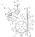
Fig. 2 is a schematic side view showing a first embodiment of an apparatus for producing an absorbent body produced by the method for producing an absorbent body of the present invention.
Fig. 3 is an enlarged side view of a supply unit included in the manufacturing apparatus shown in fig. 2.
Fig. 4 is a view schematically showing a state in which the pieces of sheet material are dispersed and conveyed by collision of the pieces of sheet material with the air flow in the duct included in the manufacturing apparatus shown in fig. 2.
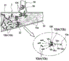
Fig. 5 is a schematic perspective view showing a second embodiment of a manufacturing apparatus for manufacturing the absorbent body shown in fig. 1.
Fig. 6 is a schematic side view of the manufacturing apparatus shown in fig. 5 viewed from the side.
Fig. 7 is a view schematically showing a state in which the pieces of sheet material are dispersed and conveyed by collision of the pieces of sheet material with the air flow in the duct included in the manufacturing apparatus shown in fig. 5.
Fig. 8 is a view schematically showing a state in which the hydrophilic fibers collide with the lump of the sheet pieces and the sheet pieces are dispersed and conveyed in the duct included in the manufacturing apparatus shown in fig. 5.
Fig. 9 is a view schematically showing a state in which the absorbent particles collide with the lump of the sheet pieces and the sheet pieces are dispersed and conveyed in the duct included in the manufacturing apparatus shown in fig. 5.
Fig. 10 is a view schematically showing a state in which the pieces of sheet material are dispersed and conveyed by colliding the pieces of sheet material with the hydrophilic fibers in the duct included in the manufacturing apparatus shown in fig. 5.
Fig. 11 is a view schematically showing a state in which the mass of the sheet pieces collides with the absorbent particles and the sheet pieces are dispersed and conveyed in the duct included in the manufacturing apparatus shown in fig. 5.
Detailed Description
As in the method for producing an absorbent body described in patent document 1, when a nonwoven fabric sheet is formed by crushing a nonwoven fabric using a crusher method, it is difficult to form a nonwoven fabric sheet having a fixed size as a whole, and variation occurs in the size with respect to a desired size. In addition, the nonwoven fabric sheets to be formed tend to have excessive fuzz, and the absorbent body is formed in a state where the nonwoven fabric sheets are connected to each other without being dispersed, thereby causing structural irregularities, which may cause a feeling of foreign matter during use or prevent the absorbent body from stably absorbing body fluid when absorbing body fluid.
In view of the above, the present invention relates to a method for producing an absorbent body containing sheet pieces made of synthetic fibers, in which the uneven distribution of the sheet pieces is suppressed.
Hereinafter, preferred embodiments of the present invention will be described with reference to the accompanying drawings. The production method of the present invention is a method for producing an absorbent body containing synthetic fibers. The absorbent body produced by the present invention is an absorbent body for an absorbent article. Absorbent articles are mainly used for absorbing and retaining body fluids excreted from the body, such as urine and menstrual blood. Absorbent articles include, for example, disposable diapers, sanitary napkins, incontinence pads, panty liners, and the like, but are not limited thereto, and articles for absorbing liquid discharged from the human body are widely included. Typically, an absorbent article includes a liquid-permeable front sheet, a liquid-impermeable or water-repellent back sheet, and a liquid-retentive absorbent body disposed between the two sheets. The absorbent body is formed by the method for producing an absorbent body of the present invention.
Fig. 1 shows a cross-sectional view of an absorbent body 100 according to an embodiment of the present invention manufactured by a method for manufacturing an absorbent body according to an embodiment of the present invention. The absorbent body 100 includes synthetic fibers 10 b. As shown in fig. 1, the absorbent body 100 includes an aggregate 100a, and the aggregate 100a includes not only synthetic fibers 10b but also hydrophilic fibers 10a and absorbent particles 10 c. Here, "including synthetic fibers 10 b" means that the sheet piece 10bh including synthetic fibers 10b has meaning. The absorbent body 100 may be a single layer or a multilayer of 2 or more layers as long as it is in a form including the synthetic fibers 10b, but the absorbent body 100 has a single-layer aggregate 100a in which the hydrophilic fibers 10a, the synthetic fibers 10b, and the absorbent particles 10c are uniformly dispersed. The aggregate 100a is a constituent member of the absorbent body 100, and the absorbent body 100 is formed by covering the aggregate 100a with the core sheet 100 b. The absorbent body 100 is long in the longitudinal direction corresponding to the front-back direction of the wearer when the absorbent article is worn.
The aggregate 100a includes a plurality of sheet pieces 10bh (hereinafter, also simply referred to as sheet pieces 10bh) including synthetic fibers 10b, and each sheet piece 10bh has a substantially rectangular shape. The average length of each sheet piece 10bh is preferably 0.3mm or more and 30mm or less, more preferably 1mm or more and 15mm or less, and particularly preferably 2mm or more and 10mm or less. Here, the average length indicates an average value of lengths of sides in the longitudinal direction when each sheet piece 10bh is rectangular. When each sheet piece 10bh is square, the average value of the lengths of any one of the four sides is shown. When the average length of the sheet pieces 10bh is 0.3mm or more, the absorbent body 100 tends to have a loose structure, and when it is 30mm or less, the wearer is less likely to be given a feeling of discomfort by the absorbent body 100, and the absorption performance is less likely to vary depending on the position in the absorbent body 100. The average width of each sheet piece 10bh is preferably 0.1mm or more and 10mm or less, more preferably 0.3mm or more and 6mm or less, and particularly preferably 0.5mm or more and 5mm or less. Here, the average width indicates an average value of the lengths of the sides in the short side direction when each sheet piece 10bh is rectangular. When each sheet piece 10bh is square, the average value of the lengths of any one of the four sides is shown. When the average width of the sheet pieces 10bh is 0.1mm or more, the absorbent body 100 tends to have a loose structure, and when it is 10mm or less, the wearer is less likely to be given a feeling of discomfort by the absorbent body 100, and the absorption performance is less likely to vary depending on the position in the absorbent body 100.
As the fiber material forming the absorbent body 100, various materials conventionally used for absorbent bodies for absorbent articles can be used without particular limitation. Examples of the hydrophilic fiber 10a include pulp fiber, rayon fiber, and cotton fiber. Examples of the synthetic fibers 10b include short fibers of polyethylene, polypropylene, polyethylene terephthalate, and the like. The sheet pieces 10bh are not particularly limited as long as they have a sheet shape, and are preferably nonwoven fabrics. The material constituting the absorbent body 100 includes absorbent particles 10c in addition to the hydrophilic fibers 10a and the synthetic fibers 10 b. Examples of the absorbent particles 10c include starch-based, cellulose-based, synthetic polymer-based, and super absorbent polymer-based particles. Examples of the super absorbent polymer include a starch-acrylic acid (salt) graft copolymer, a saponified product of a starch-acrylonitrile copolymer, a crosslinked product of sodium carboxymethyl cellulose, and a super absorbent polymer of an acrylic acid (salt) polymer. As a constituent member constituting the absorber 100, a deodorant, an antibacterial agent, or the like can be further used as necessary. The core sheet 100b may be tissue paper, liquid-permeable nonwoven fabric, or the like.
Next, a method for producing an absorbent body of the present invention will be described with reference to fig. 2 to 11.
The aggregate 100a, which is a constituent member of the absorbent body of the present invention, may be made of a material containing at least synthetic fibers 10b, and the absorbent body 100 contains sheet pieces 10bh and at least 1 different type of material different from the sheet pieces 10 bh. In the absorbent body 100, different kinds of materials include absorbent particles 10c and hydrophilic fibers 10a, as shown in fig. 1. That is, the absorbent body 100 shown in fig. 1 includes hydrophilic fibers 10a and absorbent particles 10c in addition to the synthetic fibers 10 b.
First, a method for producing an absorbent body 100 including at least synthetic fibers 10b, for example, an absorbent body 100 including an aggregate 100a obtained by removing hydrophilic fibers 10a from the absorbent body 100 in fig. 1, will be described. When a method for producing the absorbent body 100 including the aggregate 100a is described, the production apparatus 1A of the first embodiment used in the production method will be described. Fig. 2 shows a schematic configuration of the manufacturing apparatus 1A.
As shown in fig. 2, the manufacturing apparatus 1A includes: a conveyance unit 3A that conveys a raw material of the absorbent body 100; a supply unit 5A that supplies a plurality of sheet pieces 10bh from the middle of the conveyance unit 3A into the conveyance unit 3A; and a collecting and conveying section 43 disposed downstream of the conveying section 3A and having a collecting section for collecting the raw material of the absorbent body 100. The collecting pocket 41, which is an example of a collecting section, is disposed in the collecting and conveying section 43.
In the following description, the direction in which the tape-shaped synthetic fiber sheet 10bs including the synthetic fibers 10b and the absorbent body 100 are conveyed is referred to as the Y direction, the direction orthogonal to the conveying direction and in which the width direction of the synthetic fiber sheet 10bs and the absorbent body 100 are conveyed is referred to as the X direction, and the thickness direction of the synthetic fiber sheet 10bs and the absorbent body 100 which are conveyed is referred to as the Z direction.
The first direction described below is a direction extending in the conveyance direction Y, and is a direction extending in a range where an angle formed with the conveyance direction Y is less than 45 degrees. In the first embodiment and the second embodiment described below, the first direction coincides with a direction parallel to the conveyance direction Y.
The second direction described below is a direction intersecting the first direction. In the first embodiment and the second embodiment described below, the second direction is a direction orthogonal to the first direction, and coincides with a direction parallel to the width direction X of the synthetic fiber sheet 10bs and the absorbent body 100 being conveyed.
As shown in fig. 2, the conveying section 3A is formed in a hollow cylindrical shape with openings on the upstream side and the downstream side. An air blowing fan (not shown) is disposed at an upstream opening of the conveying section 3A. Further, a collecting and conveying section 43 that moves in the conveying direction Y is disposed at an opening on the downstream side of the conveying section 3A. The collecting and conveying section 43 has the collecting concave portion 41 along the conveying direction Y so that the opening of the collecting concave portion 41 faces the conveying section 3A side. The conveying section 3A extends over the entire width of the accumulating and conveying section 43. In the conveying section 3A, an air flow is generated by the operation of an air blowing fan (not shown) to cause the plurality of sheet pieces 10bh to flow toward the collecting concave portion 41 of the collecting and conveying section 43. That is, the inside of the conveying section 3A becomes the flow path 30.
As shown in fig. 2, the supply section 5A includes cutting blades 51 and 52 for cutting a tape-shaped synthetic fiber sheet 10bs including synthetic fibers 10b into sheet pieces 10bh having a predetermined length in the first direction and the second direction. The supply portion 5A has a supply nozzle 58A for supplying the sheet pieces 10bh formed by using the cutter blades 51, 52. The supply unit 5A includes: a first cutter roller 53 including a plurality of cutters 51 that cut in a first direction; and a second cutting roller 54 including a plurality of cutting knives 52 cutting in a second direction. The supply unit 5A includes 1 backup roll 55 disposed to face the first cutter roll 53 and the second cutter roll 54.
In the manufacturing apparatus 1A, as shown in fig. 2, on the surface of the first cutting roller 53, a plurality of cutting blades 51, … continuously extending along the circumferential direction of the first cutting roller 53 over the entire outer circumference of the first cutting roller 53 are arranged in the axial direction (X direction) of the first cutting roller 53. In the manufacturing apparatus 1A, the first cutting roller 53 receives power from a motor such as a motor and rotates in the direction of arrow R3. The intervals between the axially adjacent cutters 51, … of the first cutter roller 53 substantially correspond to the width (length in the short-side direction, length in the X direction) of the sheet piece 10bh formed by cutting. If the description is made more strictly, there are cases where: since the synthetic fiber sheet 10bs is cut in a state of being contracted in the width direction X by the tension at the time of sheet conveyance, the tension is released in the obtained sheet pieces 10bh, and the width of the sheet pieces 10bh becomes wider than the interval between the cutting blades 51, ….
In the manufacturing apparatus 1A shown in fig. 2, as shown in fig. 3, a plurality of cutting blades 52, … continuously extending over the entire width of the second cutter roll 54 in the axial direction of the second cutter roll 54 are arranged on the surface of the second cutter roll 54 at intervals in the circumferential direction of the second cutter roll 54. In the manufacturing apparatus 1A, the second cutter roller 54 is rotated in the direction of arrow R4 by power from a motor or the like.
In the manufacturing apparatus 1A, as shown in fig. 3, the backup roll 55 is a flat roll having a flat surface. The support roller 55 receives power from a motor or the like and rotates in the direction of arrow R5.
As shown in fig. 3, the manufacturing apparatus 1A includes, on the facing surface of the backup roller 55, the supply unit 5A, in order from the upstream side to the downstream side in the rotational direction (the direction of the arrow R5): a free roll 56 for introducing the tape-like synthetic fiber sheet 10bs between the back-up roll 55 and the first cutting roll 53; a first cutting roll 53 that cuts the tape-like synthetic fiber sheet 10bs in the first direction (Y direction); a nip roller 57 that introduces the plurality of continuous sheet piece bodies 10bh1 extending in the first direction, which are cut in the first direction, between the backup roller 55 and the second cutter roller 54; and a second cutting roller 54 that cuts the continuous body of sheet pieces 10bh1 in the second direction (X direction). The supply section 5A includes a feed roller (not shown) for feeding the tape-shaped synthetic fiber sheet 10 bs. The feed roller is configured to be rotated by a driving device such as a servo motor. From the viewpoint of preventing the slippage of the synthetic fiber sheet 10bs, the feed roller may be formed with grooves extending in the axial direction over the entire circumference of the surface thereof or subjected to a coating treatment for increasing the frictional force over the entire circumference, thereby making it less likely to slip. The slip can be prevented by nipping the sheet with the feed roller.
In the manufacturing apparatus 1A, as shown in fig. 2 and 3, the supply portion 5A has a supply nozzle 58A that supplies the plurality of sheet pieces 10bh formed by the second cutter roller 54. The supply port 581A of the supply nozzle 58A is disposed below the second cutter roll 54, that is, on the downstream side in the rotation direction (the direction of arrow R4) of the second cutter roll 54 from the closest point of approach of the second cutter roll 54 to the anvil roll 55. Further, the supply port 581A of the supply nozzle 58A extends over the entire width of the second cutter roller 54.
In the manufacturing apparatus 1A, as shown in fig. 2 and 3, the supply nozzle 58A is connected to the circumferential surface of the conveying section 3A. Then, the sheet pieces 10bh that naturally fall from the supply port 581A of the supply nozzle 58A are supplied from the middle of the conveying portion 3A to the inside of the conveying portion 3A.
Next, a first embodiment of a method for producing the absorbent body 100 in which the absorbent particles 10c are removed from the absorbent body 100 of fig. 1 will be described with reference to the production apparatus 1A of the first embodiment.
First, an air blowing fan (not shown) disposed in an opening on the upstream side of the conveying section 3A is driven. By driving the blower fan, an air flow for conveying the material of the absorber 100 to the collecting recess 41 of the collecting and conveying section 43 is generated in the conveying section 3A.
Then, a cutting step of cutting the tape-shaped synthetic fiber sheet by a predetermined length in a first direction and a second direction intersecting the first direction to form a plurality of sheet pieces is performed. More preferably, as shown in fig. 2 and 3, a cutting step is performed in which the tape-shaped synthetic fiber sheet 10bs is cut by the first cutting roll 53 and the second cutting roll 54 to form the sheet pieces 10 bh. In the cutting step, the tape-shaped synthetic fiber sheet 10bs is introduced between the first cutting roll 53 and the backup roll 55 and cut in the first direction to form a sheet piece continuous body 10bh1, using the first cutting roll 53 that cuts the tape-shaped synthetic fiber sheet 10bs by a predetermined length in the first direction (Y direction), the second cutting roll 54 that cuts the tape-shaped synthetic fiber sheet 10bs by a predetermined length in the second direction (X direction), and 1 backup roll 55 that is disposed so as to face the first cutting roll 53 and the second cutting roll 54, and the formed sheet piece continuous body 10bh1 is conveyed by the backup roll 55 and cut in the second direction between the second cutting roll 54 and the backup roll 55 to form the sheet piece 10 bh. The sheet pieces 10bh thus formed are cut only in the first direction and the second direction. The cutting step of the present embodiment will be specifically described below.
In the cutting step, the synthetic fiber sheet 10bs is conveyed by using the feed roller (not shown). The feed roller controls the conveying speed of the synthetic fiber sheet 10bs, and in the cutting step of the method for producing the absorbent body 100 of the present embodiment, the conveying speed of the synthetic fiber sheet 10bs is controlled.
In the cutting step, as shown in fig. 3, the synthetic fiber sheet 10bs conveyed from the feed roller is introduced between the support roller 55 as a flat roller rotating in the direction of the arrow R5 and the first cutter roller 53 rotating in the direction of the arrow R3 via the free roller 56, and the synthetic fiber sheet 10bs is cut in the first direction (Y direction) at positions spaced apart in the second direction (X direction) by the plurality of cutters 51, …. By cutting in this manner, a plurality of continuous sheet piece bodies 10bh1 extending in the first direction are formed, which are arranged in parallel in the second direction. The plurality of cutting blades 51, … are disposed on the surface of the first cutting roll 53 at equal intervals in the second direction. Therefore, the synthetic fiber sheet 10bs is cut at equal intervals, and thus a plurality of sheet piece continuous bodies 10bh1 having the same width (length in the second direction) are formed. From the viewpoint of ensuring the size of the sheet piece 10bh necessary for exhibiting a specific effect, the average width of the sheet piece continuous body 10bh1 formed by the cutting step is preferably 0.1mm or more and 10mm or less, more preferably 0.3mm or more and 6mm or less, and particularly preferably 0.5mm or more and 5mm or less. In the present embodiment, the width of the continuous sheet piece 10bh1 cut by the first cutting roller 53 corresponds to the length of the side in the short side direction of the finally formed sheet piece 10 bh. However, the continuous sheet segment 10bh1 cut by the first cutting roller 53 may be cut so that the width thereof corresponds to the length of the side in the longitudinal direction of the finally formed sheet segment 10bh, and in this case, the average width of the continuous sheet segment 10bh1 cut by the first cutting roller 53 is preferably 0.3mm or more and 30mm or less, more preferably 1mm or more and 15mm or less, and particularly preferably 2mm or more and 10mm or less. The formed plurality of sheet fragment continuous bodies 10bh1 are conveyed on the peripheral surface of the anvil roll 55 rotating in the arrow R5 direction, conveyed between the anvil roll 55 and the nip roll 57, and introduced between the anvil roll 55 and the second cutter roll 54 via the nip roll 57.
Then, in the cutting step, as shown in fig. 3, the plurality of continuous sheet piece bodies 10bh1 extending in the first direction and arranged in parallel in the second direction are introduced between the backup roll 55 rotating in the direction of arrow R5 and the second cutter roll 54 rotating in the direction of arrow R4, and the plurality of continuous sheet piece bodies 10bh1 are intermittently cut in the second direction in the first direction by the plurality of cutting blades 52, …. By cutting in this way, a plurality of rectangular sheet pieces 10bh having a length in the first direction longer than that in the second direction are formed. The plurality of cutters 52, … are disposed on the surface at equal intervals in the circumferential direction of the second cutter roll 54. Therefore, the plurality of sheet piece continuous bodies 10bh1 are cut at equal intervals, thereby forming a plurality of rectangular sheet pieces 10bh having equal lengths in the first direction. From the viewpoint of ensuring the size of the sheet pieces 10bh necessary to exhibit a predetermined effect, the average length of the sheet pieces 10bh formed by the cutting step is preferably 0.3mm or more and 30mm or less, more preferably 1mm or more and 15mm or less, and particularly preferably 2mm or more and 10mm or less. In the present embodiment, the length of the sheet pieces 10bh cut by the second cutter roller 54 corresponds to the length of the side of the sheet pieces 10bh in the longitudinal direction. However, the sheet pieces 10bh cut by the second cutter roller 54 may be cut so that the length thereof corresponds to the length of the side of the sheet pieces 10bh in the short side direction, and in this case, the length (width) of the sheet pieces 10bh cut by the second cutter roller 54 is preferably 0.1mm or more and 10mm or less, more preferably 0.3mm or more and 6mm or less, and particularly preferably 0.5mm or more and 5mm or less.
In the cutting step, the tape-shaped synthetic fiber sheet 10bs is cut by a predetermined length in the first direction and the second direction to obtain the sheet pieces 10bh, and therefore, the size of the obtained sheet pieces 10bh can be easily adjusted to a desired size. Since the sheet pieces 10bh having a desired size can be formed with high accuracy in this manner, an absorbent body having a desired absorption performance can be efficiently and continuously manufactured. Further, even if the sheet pieces 10bh are formed by cutting in the first direction or the second direction using the first cutter roll 53 having the cutter blade 51 or the second cutter roll 54 having the cutter blade 52, the synthetic fiber fluff may be generated by the cutting in the periphery of the formed sheet pieces 10 bh. In addition, the following are the cases: the synthetic fiber sheet material 10bs cannot be cut smoothly due to the wear and deterioration of the cutters 51 and 52 with long-term use, and the plurality of sheet pieces 10bh may be connected.
The sheet pieces 10bh obtained by cutting with the cutter rollers 53 and 54 are fed into the conveying section 3A in a freely falling manner via a feeding nozzle 58A disposed below the second cutter roller 54.
Then, a conveying step of conveying the sheet pieces 10bh supplied into the conveying portion 3A to the collecting concave portion 41 as a collecting portion is performed. However, when the sheet pieces 10bh are supplied into the conveying portion 3A, if the sheet pieces 10bh having fuzz generated around the periphery or a state where a plurality of sheet pieces 10bh are connected as described above is formed, there is a possibility that the sheet pieces 10bh having fuzz are connected to each other or the like to form a block 10K of the sheet pieces 10bh as shown in fig. 4. Therefore, in the conveying step, the sheet pieces 10bh are conveyed in a scattered state by the air flow generated in the conveying portion 3A. As shown in fig. 2 and 4, the plurality of sheet pieces 10bh cut by the plurality of cutters 52, 52 are supplied from the circumferential surface of the conveying section 3A into the flow path 30 of the conveying section 3A via the supply nozzle 58A. Further, an air flow for transporting the material of the absorbent body 100 toward the outer peripheral surface 4f of the drum 4 is already generated in the flow path 30 of the transport section 3A. Therefore, the plurality of sheet pieces 10bh are supplied to the inside of the conveying portion 3A at a position halfway in the flow direction of the air flow in the conveying portion 3A.
As shown in fig. 4, even if the block 10K of the sheet pieces 10bh is unintentionally supplied, since the speed at which the air having flowed through the flow path 30 of the conveying portion 3A flows toward the downstream side is higher than the speed at which the plurality of sheet pieces 10bh freely and fellingly supplied through the supply nozzle 58A into the flow path 30 of the conveying portion 3A from the midway toward the downstream side, if the block 10K of the sheet pieces 10bh is supplied into the flow path 30 of the conveying portion 3A, the block 10K of the sheet pieces 10bh collides with the air flow having flowed. As shown in fig. 4, the block 10K of the sheet fragments 10bh colliding with the air flow is, by the impact of the contact with the air flow, unwound at the portion where the sheet fragments 10bh are connected to each other due to the excessive entanglement caused by the nap formed at the time of cutting or the cutting failure, and separated into the individual sheet fragments 10bh and conveyed in the scattering state toward the downstream side. In this way, in the conveying step, the sheet pieces 10bh are separated into individual pieces and the sheet pieces 10bh are conveyed in a scattered state, and therefore, the aggregate 100a of the absorbent body 100 in which the sheet pieces 10bh are uniformly distributed is easily and stably produced. The velocity of the air flow is preferably 3m/sec or more and 150m/sec or less, more preferably 10m/sec or more and 100m/sec or less, and particularly preferably 15m/sec or more and 50m/sec or less. Within this range, the individual pieces of sheet material 10bh can be more effectively separated and transported in a scattered state, and the aggregate 100a of the absorbent body 100 in which the pieces of sheet material 10bh are uniformly distributed can be easily and stably produced.
Next, a collecting step of collecting the plurality of sheet pieces 10bh conveyed in the conveying step into the collecting recesses 41 as collecting portions to obtain a collection 100a as a constituent member of the absorbent body 100 is performed. In the collecting step, the aggregates 100a of the raw material of the absorbent body are formed, which are conveyed so that the sheet pieces 10bh are arranged substantially uniformly and collected over the entire area of the collecting recesses 41 of the collecting and conveying section 43. The aggregates 100a thus formed in the aggregation recesses 41 are continuously produced along the conveying direction of the aggregation conveyor 43. Then, after the aggregate 100a in which the sheet pieces 10bh are aggregated is obtained in the aggregation concave portion 41, the aggregate 100a is released from the aggregation concave portion 41. Then, the absorbent particles 10c are spread on the aggregate 100a by a spreading device not shown. Then, the aggregate 100a is transferred to the band-shaped core sheet 100b, and a band-shaped absorbent body 100 in which the aggregate 100a is wrapped with the core sheet 100b is manufactured using, for example, a folding guide plate (not shown). Then, the band-shaped absorbent body 100 is cut at predetermined intervals in the transport direction Y by a cutting device (not shown) to produce individual absorbent bodies 100. The absorbent body 100 thus manufactured has an aggregate 100a in which the sheet pieces 10bh are uniformly gathered over substantially the entire area.
As described above, in the manufacturing method using the manufacturing apparatus 1A, since the sheet pieces 10bh are conveyed in a scattered state by the air flow generated inside the conveying section 3A, the absorbent body 100 in which the uneven distribution of the sheet pieces 10bh is suppressed can be stably manufactured. In this way, in the aggregate 100a of the absorbent body 100 thus manufactured, since the distribution unevenness of the sheet pieces 10bh is suppressed, a feeling of foreign matter is less likely to occur in use of the absorbent article having the absorbent body 100, and when the absorbent body 100 absorbs bodily fluids, the bodily fluids can be stably absorbed.
Next, a method for manufacturing the absorbent body 100 shown in fig. 1 will be described with reference to fig. 5 to 11, taking as an example a method for manufacturing the absorbent body 100 shown in fig. 1. Fig. 5 and 6 show the overall configuration of a manufacturing apparatus 1 according to a second embodiment for carrying out the manufacturing method according to the second embodiment. When the method of manufacturing the absorbent body 100 according to the second embodiment is described, the manufacturing apparatus 1 is described first. Note that, in the manufacturing apparatus 1 of the second embodiment to be described below, differences from the manufacturing apparatus 1A of the first embodiment will be mainly described, and the same components as those of the manufacturing apparatus 1A will be denoted by the same reference numerals and their description will be omitted.
As shown in fig. 5 and 6, the manufacturing apparatus 1 for manufacturing the absorbent body 100 shown in fig. 1 includes, from the upstream side toward the downstream side in the transport direction: a defibering unit 2 for defibering the hydrophilic sheet 10as containing the hydrophilic fibers 10a by using a defibering machine 21; a duct 3 as a transport section that transports the raw material of the absorbent body 100 with an air flow; a supply unit 5 that supplies the sheet pieces 10bh from the middle of the duct 3 to the inside of the duct 3; a drum 4 disposed adjacent to the downstream side of the duct 3 and having a collecting portion for collecting the raw material of the absorbent body 100; a pressing belt 7 disposed along an outer peripheral surface 4f of the drum 4 on the opposite side to the conduit 3; and a vacuum conveyor 8 disposed below the drum 4. In the manufacturing apparatus 1, a collecting recessed portion 41 as an example of a collecting portion is disposed on the outer peripheral surface of the drum 4. The supply unit 5 of the manufacturing apparatus 1 for supplying the sheet pieces 10bh has the same configuration as the supply unit 5A except that the supply nozzle 58A of the supply unit 5A of the manufacturing apparatus 1A is the suction nozzle 58 described below.
As shown in fig. 5 and 6, the manufacturing apparatus 1 includes a defibration section 2 for defibrating a band-shaped hydrophilic sheet 10as containing hydrophilic fibers 10 a. The defibering unit 2 includes a defibering machine 21 that defibers the hydrophilic sheet 10as and a housing 22 that covers the upper side of the defibering machine 21. The defibration section 2 is a portion for supplying the defibrated hydrophilic fibers 10a, which are the raw material of the absorbent body 100, into the duct 3. The defibering unit 2 further includes a pair of feed rollers 23 and 23 for feeding the hydrophilic sheet 10as to the defibering machine 21 in the manufacturing apparatus 1.
At least one of the pair of feed rollers 23, 23 is configured to be rotated by a driving device not shown. The pair of feed rollers 23, 23 are nip rollers. The driving device may be a servo motor, for example. From the viewpoint of preventing the slippage of the hydrophilic sheet 10as, it is preferable that both of the pair of feed rollers 23, 23 are rotated by the driving device. In this case, the pair of feed rollers 23 and 23 may be directly driven by the driving device, or one roller may be driven by the driving device and the other roller may be driven by a transmission unit such as a gear. In order to further prevent the slippage with the hydrophilic sheet 10as, the pair of feed rollers 23 and 23 may be formed with grooves extending in the axial direction over the entire circumference of the surfaces thereof, so that the slippage is not likely to occur. In addition, rollers for assisting the conveyance of the hydrophilic sheet 10as may be provided in addition to the pair of feed rollers 23, 23.
As shown in fig. 5 and 6, the manufacturing apparatus 1 includes a duct 3 as a transport unit for transporting a raw material of the aggregate 100a of the absorbent body 100. The duct 3 extends from the defibration section 2 to the drum 4, and an opening on the downstream side of the duct 3 covers an outer peripheral surface 4f of the space a of the drum 4 maintained at a negative pressure. The duct 3 has a top plate 31 forming a top surface, a bottom plate 32 forming a bottom surface, and two side walls 33, 34 forming both side surfaces. By the operation of the air supply fan (not shown) of the drum 4, an air flow is generated in the duct 3 surrounded by the top plate 31, the bottom plate 32, and the side walls 33 and 34, so that the raw material of the absorbent body 100 flows toward the outer peripheral surface 4f of the drum 4. That is, the inside of the duct 3 becomes the flow path 30.
As shown in fig. 5 and 6, the manufacturing apparatus 1 includes an absorbent particle dispersion pipe 36 for supplying the absorbent particles 10c into the duct 3 on the ceiling 31 of the duct 3. The absorbent particle dispersion pipe 36 discharges the absorbent particles 10c from a dispersion port provided at the front end of the absorbent particle dispersion pipe 36 via a device such as a screw feeder (not shown) and supplies the absorbent particles to the inside of the duct 3. Further, the amount of the absorbent particles 10c supplied to the absorbent particle dispersion pipe 36 can be adjusted by means of a screw feeder or the like.
As shown in fig. 5 and 6, the manufacturing apparatus 1 has a drum 4. The drum 4 has an aggregation recess 41 as an aggregation portion for aggregating the raw material of the absorbent body to obtain an aggregate on the outer peripheral surface 4f thereof. The drum 4 is cylindrical, and receives power from a motor (not shown) such as a motor to rotate the member 40 forming the outer peripheral surface 4f about the horizontal axis in the direction of arrow R1. The drum 4 includes a member 40 forming an outer peripheral surface 4f and a drum main body 42 located inside the member 40. The cartridge body 42 is fixed without rotation. In the manufacturing apparatus 1, the collecting concave portions 41 of the bowl 4 are continuously arranged over the entire circumference of the bowl 4 in the circumferential direction (2Y direction). In the figure, 2Y is the circumferential direction of the drum 4, and X is the width direction of the drum 4 (the direction parallel to the rotation axis of the drum 4). In this way, the collecting recessed portions 41 of the manufacturing apparatus 1 are arranged continuously over the entire circumference of the drum 4 in the circumferential direction 2Y, but may be arranged in plural at predetermined intervals in the circumferential direction 2Y of the drum 4.
As shown in fig. 5 and 6, the tube main body 42 of the drum 4 has a plurality of spaces, for example, 3 spaces a to C, inside thereof, which are independent of each other. The spaces a to C are partitioned by plates provided from the rotation axis side of the bowl 4 toward the outer peripheral surface 4f side. An intake fan (not shown) as an intake mechanism is connected to the bowl 4, and the pressure in the plurality of partitioned spaces in the bowl 4 can be adjusted by driving the intake fan. In the manufacturing apparatus 1, the suction force in the region corresponding to the space a located on the upstream side of the region where the outer peripheral surface 4f is covered with the duct 3 can be made stronger or weaker than the suction force in the regions corresponding to the spaces B to C located on the downstream side, and the space a can be maintained at a negative pressure. The method of partitioning the space of the cylinder main body 42 is not limited to the above-described embodiment. For example, it is also possible to further divide the space a of the cylinder main body 42 maintained at the negative pressure into a plurality of spaces, and to enable adjustment of the pressure for each of the finely divided spaces. For example, the space B of the cylinder main body 42 may be further divided into a plurality of spaces, and the pressure may be adjusted for each of the finely divided spaces, and the pressure in the space closest to the space a may be adjusted to the pressure in the space a, and the pressure in the collecting concave portion 41 may be set to a negative pressure region until it is separated from the substantially front side of the conduit 3.
As shown in fig. 3 and 4, the member 40 forming the outer peripheral surface 4f is disposed so as to cover the entire periphery of the cylinder main body 42, and receives power from a motor such as a motor to rotate around the horizontal axis of the cylinder main body 42 in the direction of arrow R1. The member 40 forming the outer peripheral surface 4f is formed with a collecting recess 41.
The bottom surface of the collecting recessed portion 41 is formed of a porous member (not shown), and the porous member functions as a suction hole for sucking the raw material of the absorbent body 100 while the collecting recessed portion 41 in the outer peripheral surface 4f passes through the space maintained at the negative pressure in the drum 4.
In the manufacturing apparatus 1, as shown in fig. 5 and 6, the supply section 5 has a suction nozzle 58 that sucks the sheet pieces 10bh formed using the cutting blades 51, 52. The suction port of the suction nozzle 58 has the same configuration as the supply port 581A of the supply nozzle 58A in the supply unit 5A shown in fig. 3. The suction port of the suction nozzle 58 is disposed below the second cutter roll 54, i.e., on the downstream side in the rotational direction (the direction of arrow R4) of the second cutter roll 54 from the closest point of approach of the second cutter roll 54 to the anvil roll 55, similarly to the supply port 581A shown in fig. 3. In addition, the suction opening of the suction nozzle 58 extends over the entire width of the second cutting roll 54. From the viewpoint of improving the suction performance of the sheet pieces 10bh, it is preferable that the suction port of the suction nozzle 58 is disposed below the anvil roll 55 and the second cutter roll 54 so as to face between the anvil roll 55 and the second cutter roll 54, similarly to the supply port 581A shown in fig. 3. In addition, from the viewpoint of further improving the suction performance of the sheet pieces 10bh, it is preferable that the suction port of the suction nozzle 58 is covered on the outer surface of the second cutter roll 54 so that the length of the arc of the suction port facing the second cutter roll 54 is longer than the length of the arc of the suction port facing the anvil roll 55 when the anvil roll 55 and the second cutter roll 54 are viewed from the side, similarly to the supply port 581A shown in fig. 3.
The suction nozzle 58 is connected to the top plate 31 side of the duct 3 via a supply pipe 59. The supply pipe 59 extends in a direction intersecting the flow direction of the air flow of the duct 3 as the conveyance section. Then, the sheet pieces 10bh sucked from the suction port of the suction nozzle 58 are supplied from midway of the duct 3 to the inside of the duct 3 via the supply pipe 59. In the manufacturing apparatus 1, the connection position between the supply pipe 59 and the duct 3 is located between the side of the defibration section 2 and the side of the drum 4 in the duct 3, and is located on the downstream side of the absorbent particle dispersion pipe 36 in the duct 3. However, the connection position of the supply pipe 59 and the duct 3 is not limited to this, and for example, the bottom plate 32 side of the duct 3 may be set instead of the top plate 31 side of the duct 3.
The manufacturing apparatus 1 includes a press belt 7 and a vacuum conveyor 8 in addition to the above-described defibration section 2, the duct 3, the drum 4, and the supply section 5.
In the manufacturing apparatus 1, as shown in fig. 5 and 6, the pressing belt 7 is disposed along the outer peripheral surface 4f of the drum 4 located in the space B, adjacent to the downstream side of the position of the duct 3. The space B is set to a weaker negative pressure or zero pressure (atmospheric pressure) than the space a of the bowl 4. The pressing belt 7 is an annular air-permeable or non-air-permeable belt, is mounted on the rollers 71 and 72, and rotates together with the rotation of the drum 4. When the pressing belt 7 is an air-permeable belt, it is preferable that the material in the collecting concave portion 41 does not substantially pass through. By pressing the belt 7, even if the pressure in the space B is set to the atmospheric pressure, the aggregates 100a in the collecting concave portion 41 can be held in the collecting concave portion 41 before being transferred to the vacuum conveyor 8.
In the manufacturing apparatus 1, the vacuum conveyor 8 is disposed below the drum 4 and on the outer peripheral surface 4f of the drum 4 in the space C set at a weak positive pressure or zero pressure (atmospheric pressure), as shown in fig. 5 and 6. For example, a weak positive pressure can be obtained by blowing air from the inside of the tube main body 42 to the outside of the outer peripheral surface 4 f. The vacuum conveyor 8 includes: an endless air-permeable belt 83 stretched over the driving roller 81 and the driven rollers 82 and 82; and a vacuum box 84 disposed at a position facing the outer peripheral surface 4f of the drum 4 located in the space C through the air-permeable belt 83. The core-spun sheet 100b including tissue paper, liquid-permeable nonwoven fabric, or the like is introduced onto the vacuum conveyor 8.
The manufacturing apparatus 1 further includes a folding guide plate (not shown) that folds back the core sheet 100b in the width direction (X direction) so as to cover the core sheet 100b and the aggregates 100a transferred onto the core sheet 100b on the downstream side of the vacuum conveyor 8. The folding guide plate is a member that folds back both side portions of the core-spun sheet 100b along the conveying direction (Y direction) onto the aggregate 100a in the manufacturing apparatus 1. The manufacturing apparatus 1 further includes a cutting device (not shown) on the downstream side of the fold guide plate, and individual absorbent bodies 100 are manufactured by the cutting device.
Next, a method for producing the absorbent body 100 using the production apparatus 1 of the second embodiment, that is, a second embodiment of the method for producing an absorbent body of the present invention will be described.
First, the space a in the drum 4 and the vacuum box 84 for the vacuum conveyor 8 are set to negative pressure by operating air supply fans (not shown) connected to them. By setting the space a to a negative pressure, an air flow for transporting the material of the absorbent body 100 to the outer peripheral surface 4f of the drum 4 is generated in the duct 3. Further, the defibrator 21 and the drum 4 are rotated, and the first cutter roller 53, the second cutter roller 54, and the backup roller 55 are rotated, so that the pressing belt 7 and the vacuum conveyor 8 are operated.
Then, in the second embodiment, a defibering step is performed in which the hydrophilic sheet 10as in a belt shape is fed to the defibering machine 21 using the feed roller 23 and is defibered to obtain the hydrophilic fibers 10 a. The pair of feed rollers 23, 23 controls the feeding speed of the hydrophilic sheet 10as to the defibrator 21. In the defibering step, the supply of the hydrophilic sheet 10as to the defibering machine 21 is controlled.
In the defibering step, as shown in fig. 5 and 6, the hydrophilic sheet 10as supplied to the defibering machine 21 is defibered, and the hydrophilic fibers 10a, which are the defibered fiber material, are supplied from the defibering machine 21 to the duct 3.
The method for producing the absorbent body 100 further includes a cutting step in addition to the defibration step. In the cutting step, as shown in fig. 3, the tape-shaped synthetic fiber sheet 10bs is cut by the first cutting roll 53 and the second cutting roll 54 to form the sheet pieces 10 bh. In the cutting step, the tape-shaped synthetic fiber sheet 10bs is introduced between the first cutting roll 53 and the backup roll 55 and cut in the first direction to form a sheet piece continuous body 10bh1, using the first cutting roll 53 that cuts the tape-shaped synthetic fiber sheet 10bs by a predetermined length in the first direction (Y direction), the second cutting roll 54 that cuts the tape-shaped synthetic fiber sheet 10bs by a predetermined length in the second direction (X direction), and 1 backup roll 55 that is disposed so as to face the first cutting roll 53 and the second cutting roll 54, and the formed sheet piece continuous body 10bh1 is conveyed by the backup roll 55 and cut in the second direction between the second cutting roll 54 and the backup roll 55 to form the sheet piece 10 bh. The sheet pieces 10bh thus formed are cut only in the first direction and the second direction.
Then, a suction step of sucking the sheet pieces 10bh cut by the cutter rollers 53 and 54 and supplying the sheet pieces to the inside of the duct 3 using a suction nozzle 58 disposed below the second cutter roller 54 is performed. When the suction port of the suction nozzle 58 is disposed below the second cutter roll 54, that is, downstream of the closest point of contact between the second cutter roll 54 and the anvil roll 55 in the rotation direction of the second cutter roll 54 (the direction of arrow R4 shown in fig. 6), the plurality of sheet pieces 10bh cut by the second cutter roll 54 and the anvil roll 55 can be efficiently sucked.
Then, a conveying step of conveying the sheet pieces 10bh supplied to the inside of the duct 3 to the collecting concave portion 41 using the duct 3 is performed. In the conveying step, the sheet pieces 10bh are conveyed in a scattered state by the air flow generated in the duct 3. As shown in fig. 5 and 6, the plurality of sheet pieces 10bh sucked in the suction step are supplied from the top plate 31 side of the duct 3 into the flow path 30 of the duct 3 via the supply pipe 59 of the suction nozzle 58. Further, in the flow path 30 of the duct 3, an air flow has been generated which transports the raw material of the absorbent body 100 toward the outer peripheral surface 4f of the drum 4. Therefore, the plurality of sheet fragments 10bh are supplied to the inside of the duct 3 at a position just midway in the flow direction of the air flow in the duct 3.
As shown in fig. 7, even if the block 10K of the sheet pieces 10bh is unintentionally supplied, since the velocity of the air that has flowed into the flow path 30 of the duct 3 toward the downstream side is higher than the velocity of the plurality of sheet pieces 10bh supplied from halfway into the flow path 30 of the duct 3 through the supply pipe 59 toward the downstream side, if the block 10K of the sheet pieces 10bh is supplied into the flow path 30 of the duct 3, the block 10K of the sheet pieces 10bh collides with the air that has flowed. As shown in fig. 7, the block 10K of the sheet pieces 10bh colliding with the air flow unwinds the entanglement or the like of the nap formed at the time of cutting by the impact of the contact with the air flow, separates the sheet pieces 10bh into individual pieces, and conveys the sheet pieces 10bh in a scattered state toward the downstream side. In this way, in the conveying step of the second embodiment, the sheet pieces 10bh are separated into individual sheet pieces 10bh and conveyed in a scattered state, and therefore, the aggregates 100a of the absorbent body 100 in which the sheet pieces 10bh are uniformly distributed are easily and stably produced.
The absorbent body 100 produced by the method for producing an absorbent body contains the hydrophilic fibers 10a as different kinds of materials. In the conveying step, while the sheet pieces 10bh obtained in the cutting step and the hydrophilic fibers 10a obtained in the defibering step are conveyed to the collecting concave portion 41, the sheet pieces 10bh and the hydrophilic fibers 10a are collided in an air flow, and the sheet pieces 10bh and the hydrophilic fibers 10a are conveyed by the air flow in a scattered state in which both are mixed.
In the conveying step, the hydrophilic fibers 10a and the sheet pieces 10bh, which are different types of materials, are supplied to different positions in the flow direction of the air flow in the duct 3 (the flow path 30), and the hydrophilic fibers 10a are supplied to the upstream side of the position where the sheet pieces 10bh are supplied in the flow direction of the air flow and conveyed. That is, as shown in fig. 5 and 6, the defibrator 21 used in the defibration process is disposed on the upstream side of the duct 3 with respect to the suction nozzle 58. In the conveying step, the hydrophilic fibers 10a obtained in the defibering step are supplied into the flow path 30 of the duct 3 from the upstream side in the flow direction of the air flow in the duct 3, and the plurality of sheet fragments 10bh having passed through the suction step are supplied into the flow path 30 of the duct 3 from the middle of the duct 3. In the conveying step, the hydrophilic fibers 10a supplied from the defibrator 21 to the inside of the flow path 30 of the duct 3 are conveyed to the outer peripheral surface 4f of the drum 4 from the upstream side in the flow direction of the air flow from the position where the plurality of sheet pieces 10bh are supplied by the air flow flowing through the flow path 30 of the duct 3.
Here, in the conveying step, when the sheet pieces 10bh and the hydrophilic fiber 10a as the different kind of material are merged in the inside of the catheter 3, the conveying speed Vb of the sheet pieces 10bh is different from the conveying speed Va of the hydrophilic fiber 10 a. Further, a downstream-side velocity component Va1 of the conveyance speed Va of the hydrophilic fiber 10a is larger than a downstream-side velocity component Vb1 of the conveyance speed Vb of the sheet piece 10 bh. Here, the downstream-side velocity component Va1 in the transport velocity Va of the hydrophilic fiber 10a is a velocity component in the horizontal direction when the catheter 3 is viewed from the lateral surface side and projected as shown in fig. 8, and the transport velocity Va is decomposed into a velocity component Va1 in the horizontal direction and a velocity component Va2 in the vertical direction. Similarly, the velocity component Vb1 on the downstream side in the transport velocity Vb of the sheet piece 10bh is a velocity component in the horizontal direction in the case where the transport velocity Vb is decomposed into a velocity component Vb1 in the horizontal direction and a velocity component Vb2 in the vertical direction when the duct 3 is viewed from the side surface side and projected as shown in fig. 8. In the conveying step, since the hydrophilic fibers 10a are supplied from the upstream side of the sheet pieces 10bh, when the sheet pieces 10bh are merged with the hydrophilic fibers 10a, the downstream-side velocity component Va1 of the hydrophilic fibers 10a is larger than the downstream-side velocity component Vb1 of the sheet pieces 10 bh. Particularly in the second embodiment, the sheet pieces 10bh are supplied to the flow path 30 of the duct 3 through the supply pipe 59 extending in the direction intersecting the flow direction of the air flow of the duct 3. Therefore, since the velocity component to the downstream side in the flow direction in the conduit 3 is not large in the moving velocity of the sheet pieces 10bh immediately before being supplied to the flow path 30 of the conduit 3, the downstream-side velocity component Va1 in the transport velocity Va of the hydrophilic fiber 10a is likely to be larger than the downstream-side velocity component Vb1 in the transport velocity Vb of the sheet pieces 10 bh. Therefore, even if the pieces 10K of the sheet pieces 10bh are unintentionally supplied into the flow path 30 of the duct 3, the pieces 10K of the sheet pieces 10bh collide with the hydrophilic fibers 10a that have already flowed. As shown in fig. 8, the lump 10K of the sheet pieces 10bh colliding with the hydrophilic fibers 10a further unravels the entanglement or the like of the nap formed at the time of cutting by the impact of the contact with the hydrophilic fibers 10a, separates into individual sheet pieces 10bh, and conveys the sheet pieces in a scattered state toward the downstream side. In the conveying step, the hydrophilic fibers 10a collide with the lumps 10K of the sheet pieces 10bh, and the individual sheet pieces 10bh are further separated, and the hydrophilic fibers 10a and the sheet pieces 10bh are conveyed by the air flow while being mixed in a scattering state, so that even when the sheet pieces 10bh having fuzz generated around them or a state in which a plurality of sheet pieces 10bh are connected before being supplied into the duct 3 is formed, the aggregates 100a of the absorbent body 100 in which the sheet pieces 10bh and the hydrophilic fibers 10a are uniformly distributed can be easily and stably produced.
The absorbent body 100 produced by the method for producing the absorbent body 100 contains absorbent particles 10c as different types of materials in addition to the hydrophilic fibers 10 a. In the conveying step, in addition to the collision between the sheet pieces 10bh and the hydrophilic fibers 10a, while the sheet pieces 10bh and the absorbent particles 10c obtained in the cutting step are conveyed to the collecting concave portion 41, the sheet pieces 10bh and the absorbent particles 10c are collided in the air flow, and the sheet pieces 10bh and the absorbent particles 10c are conveyed by the air flow in a scattered state in which they are mixed.
In the conveying step, the absorbent particles 10c and the sheet pieces 10bh, which are different types of materials, are supplied to different positions along the flow direction of the air flow, and the absorbent particles 10c are supplied to and conveyed on the upstream side of the position where the sheet pieces 10bh are supplied in the flow direction of the air flow. That is, as shown in fig. 5 and 6, the absorbent particle dispersion pipe 36 is disposed upstream of the suction nozzle 58 with respect to the duct 3. In the conveying step, the absorbent particles 10c are supplied into the flow path 30 of the duct 3 from the upstream side of the duct 3 from the suction nozzle 58, and the plurality of sheet pieces 10bh having passed through the suction step are supplied into the flow path 30 of the duct 3 from the downstream side of the duct 3 from the position where the absorbent particle dispersion tube 36 is arranged. In the conveying step, the absorbent particles 10c supplied from the absorbent particle dispersion pipe 36 into the flow path 30 of the duct 3 are conveyed toward the outer peripheral surface 4f of the drum 4 from the upstream side in the flow direction of the air flow from the position where the plurality of sheet pieces 10bh are supplied by the air flow flowing through the flow path 30 of the duct 3.
Here, in the conveying step, when the sheet pieces 10bh are merged with the absorbent particles 10c, which are different kinds of materials, the conveying speed Vb of the sheet pieces 10bh is different from the conveying speed Vc of the absorbent particles 10 c. Further, a downstream-side velocity component Vc1 of the conveyance velocity Vc of the absorbent particles 10c is larger than a downstream-side velocity component Vb1 of the conveyance velocity Vb of the sheet pieces 10 bh. The downstream-side velocity component Vc1 of the transport velocity Vc of the absorbent particles 10c is a velocity component in the horizontal direction when the transport velocity Vc is decomposed into the horizontal-direction velocity component Vc1 and the vertical-direction velocity component Vc2 when the duct 3 is viewed from the side surface side and projected as shown in fig. 9. In the conveying step, since the absorbent particle 10c is supplied from a position on the upstream side of the sheet piece 10bh, when the sheet piece 10bh and the absorbent particle 10c meet, the downstream-side velocity component Vc1 of the absorbent particle 10c is larger than the downstream-side velocity component Vb1 of the sheet piece 10 bh. Therefore, if the pieces 10K of the sheet pieces 10bh are supplied into the flow path 30 of the duct 3, the pieces 10K of the sheet pieces 10bh collide with the absorbent particles 10c that have flowed. As shown in fig. 9, the lump 10K of the sheet pieces 10bh colliding with the absorbent particles 10c further unravels the entanglement or the like of the nap formed at the time of cutting by the impact of the contact with the absorbent particles 10c, separates into individual sheet pieces 10bh, and conveys the sheet pieces 10bh toward the downstream side in a scattered state. In the conveying step of the second embodiment, the lump 10K of the sheet pieces 10bh collides with the hydrophilic fibers 10a in the air flow and also collides with the absorbent particles 10c, whereby the individual sheet pieces 10bh are further separated, and the hydrophilic fibers 10a, the sheet pieces 10bh, and the absorbent particles 10c are conveyed by the air flow while being mixed in a scattered state, and therefore, the aggregate 100a of the absorbent body 100 in which the hydrophilic fibers 10a, the sheet pieces 10bh, and the absorbent particles 10c are uniformly distributed is easily and stably produced. In particular, since the absorbent particles 10c have a larger specific gravity than the sheet pieces 10bh, the respective sheet pieces 10bh are more easily separated. The velocity of the air flow in the flow channel 30 of the duct 3 is preferably 3m/sec or more and 150m/sec or less, more preferably 10m/sec or more and 100m/sec or less, and particularly preferably 15m/sec or more and 50m/sec or less. Within this range, the hydrophilic fibers 10a and the absorbent particles 10c, which are different types of materials, can be more effectively caused to collide with the mass 10K of the sheet pieces 10bh, and the sheet pieces 10bh can be further separated into individual sheet pieces 10bh and conveyed in a scattered state, and the aggregate 100a of the absorbent body 100 in which the sheet pieces 10bh are uniformly distributed can be easily and stably produced.
Then, a collecting step of collecting not only the sheet pieces 10bh conveyed in a scattered state by the air flow in the conveying step to the collecting concave portion 41 disposed on the outer peripheral surface 4f of the drum 4 but also the hydrophilic fibers 10a and the absorbent particles 10c to the collecting concave portion 41 disposed on the outer peripheral surface 4f of the drum 4 is performed to obtain a collection 100 a. In the collecting step, the individual pieces of sheet material 10bh are separated and conveyed in a scattered state in the conveying step, and therefore the pieces of sheet material 10bh are uniformly mixed and collected to substantially the entire region of the aggregate 100a in a plan view.
As described above, the sheet pieces 10bh are conveyed so that the sheet pieces 10bh are substantially uniformly arranged over the entire region of the collecting concave portion 41 of the drum 4, and the aggregate 100a of the raw material of the absorbent body in which the hydrophilic fibers 10a, the sheet pieces 10bh, and the absorbent particles 10c are mixed and collected is formed. The aggregates 100a thus formed in the aggregation recesses 41 are continuously produced over the entire circumference of the bowl 4 in the circumferential direction 2Y. After the aggregates 100a in which the hydrophilic fibers 10a, the synthetic fibers 10B, and the absorbent particles 10c are aggregated are obtained in the aggregation concave portions 41, as shown in fig. 5, the aggregates 100a in the aggregation concave portions 41 are pressed by the pressing belt 7 disposed on the outer peripheral surface 4f of the drum 4 located in the space B while the drum 4 is further rotated, and are conveyed to the vacuum conveyor 8.
Then, as shown in fig. 5 and 6, when the aggregates 100a in the collecting dents 41 reach the position opposite to the vacuum box 84 located in the space C of the drum 4, the aggregates are released from the collecting dents 41 by suction from the vacuum box 84. Then, the aggregates 100a continuously extending in the conveying direction Y are conveyed to the central portion in the width direction X of the belt-like core-spun sheet 100b introduced onto the vacuum conveyor 8.
Next, as shown in fig. 5, one of both side portions of the core-spun sheet 100b in the conveying direction Y is folded back onto the aggregate 100a inward in the width direction X by a folding guide plate (not shown). Then, the other side portion is folded back to the aggregate 100a inward in the width direction X by the folding guide plate, and a band-shaped absorbent body 100 in which the aggregate 100a is covered with the core-spun sheet 100b is manufactured.
Then, the band-shaped absorbent body 100 is cut at a specific interval in the transport direction Y by a cutting device (not shown) to produce individual absorbent bodies 100. The absorbent body 100 thus manufactured has an aggregate 100a in which the hydrophilic fibers 10a, the sheet pieces 10bh, and the absorbent particles 10c are uniformly mixed and aggregated over substantially the entire region and are coated with the core-spun sheet 100b, as shown in fig. 1.
As described above, the manufacturing method using the manufacturing apparatus 1 includes, as shown in fig. 5: a conveying step of conveying the plurality of sheet pieces 10bh to the collecting concave portion 41 serving as a collecting portion using the duct 3 serving as a conveying portion; and an aggregation step of aggregating the plurality of sheet pieces 10bh conveyed in the conveyance step into an aggregation recess 41 serving as an aggregation portion to obtain an aggregate 100a serving as a constituent member of the absorbent body 100. Further, since the sheet pieces 10bh are conveyed in a scattered state by the air flow generated inside the duct 3, the absorbent body 100 in which the uneven distribution of the sheet pieces 10bh is suppressed can be stably manufactured. In particular, in the second embodiment, even if the block 10K of the sheet pieces 10bh is unintentionally supplied, the hydrophilic fibers 10a collide with the block 10K of the sheet pieces 10bh by the air flow, and the block 10K is separated into individual sheet pieces 10bh and conveyed in a scattered state, and therefore the individual sheet pieces 10bh are easily scattered. Further, since the absorbent particles 10c are caused to collide with the mass 10K of the sheet pieces 10bh in the air flow, the individual sheet pieces 10bh are more easily dispersed. In particular, the above-described effect is significant and useful in the sheet pieces 10bh formed in the cutting step of cutting a tape-shaped synthetic fiber sheet including the synthetic fibers 10b by a predetermined length in the first direction and the second direction.
As described above, the method of manufacturing the absorbent body 100 allows the sheet pieces 10bh to be easily distributed over substantially the entire area of the absorbent body 100. As described above, if the distribution unevenness of the sheet pieces 10bh is suppressed in the aggregate 100a of the absorbent body 100, a feeling of foreign matter is less likely to occur in use of the absorbent article having the absorbent body 100, and when the absorbent body 100 absorbs body fluid, the body fluid can be stably absorbed.
The present invention is not limited to the above embodiments and may be modified as appropriate.
For example, in the conveying step of the second embodiment, even if the block 10K of the sheet piece 10bh is unintentionally supplied, the hydrophilic fibers 10a and the absorbent particles 10c, which are different kinds of materials, collide with the block 10K of the sheet piece 10bh and are separated into the sheet piece 10bh, but the air flow may collide with the block 10K of the sheet piece 10bh and either one of the hydrophilic fibers 10a and the absorbent particles 10c may collide with the block 10K of the sheet piece 10bh and be separated into the sheet piece 10 bh.
In the conveying step of the second embodiment, the hydrophilic fiber 10a as a different type of material is supplied on the upstream side of the position where the sheet piece 10bh is supplied, but the hydrophilic fiber 10a may be supplied on the downstream side of the position where the sheet piece 10bh is supplied. When the position at which the hydrophilic fibers 10a are supplied is set to the downstream side of the position at which the sheet pieces 10bh are supplied, even if the block 10K of the sheet pieces 10bh is unintentionally supplied, as shown in fig. 10, when the sheet pieces 10bh and the hydrophilic fibers 10a merge, the block 10K of the sheet pieces 10bh flowing from the upstream side collides with the hydrophilic fibers 10a in the air flow, and the block 10K is separated into individual sheet pieces 10bh and conveyed by the air flow in a scattered state. Therefore, the aggregate 100a of the absorbent body 100 in which the uneven distribution of the sheet pieces 10bh is suppressed can be easily and stably produced.
In the conveying step of the second embodiment, the absorbent particles 10c, which are different types of materials, are supplied on the upstream side of the position where the sheet pieces 10bh are supplied, but the absorbent particles 10c may be supplied on the downstream side of the position where the sheet pieces 10bh are supplied. When the position at which the absorbent particles 10c are supplied is set to the downstream side of the position at which the sheet pieces 10bh are supplied, even if the mass 10K of the sheet pieces 10bh is not intentionally supplied, as shown in fig. 11, when the sheet pieces 10bh and the absorbent particles 10c merge, the mass 10K of the sheet pieces 10bh flowing from the upstream side collides with the absorbent particles 10c in the air flow, and the mass 10K is separated into the individual sheet pieces 10bh and is conveyed by the air flow in a scattered state. Therefore, the aggregate 100a of the absorbent body 100 in which the uneven distribution of the sheet pieces 10bh is suppressed can be easily and stably produced.
In the method for manufacturing the absorbent body 100, the sheet pieces 10bh are formed by the cutting step, but the sheet pieces 10bh may be cut in advance by a predetermined length without including the cutting step in the production line. In the cutting step of the first and second embodiments, the synthetic fiber sheet 10bs is cut by using the first and second cutter rolls 53 and 54, but the synthetic fiber sheet 10bs may be cut by using 1 cutter roll having the cutter 51 for cutting in the first direction and the cutter 52 for cutting in the second direction on the same peripheral surface, instead of 2 cutter rolls. When the above-described 1 cutter roll is used, it is preferable to use 1 anvil roll disposed to face the 1 cutter roll. In the manufacturing apparatus having the 1 cutter roll and the 1 anvil roll, it is preferable that the suction port of the suction nozzle 58 is disposed below the 1 cutter roll.
In the cutting step of the first and second embodiments, the tape-shaped synthetic fiber sheet 10bs is cut into pieces 10bh having a predetermined length in the first and second directions by using the first cutter roll 53 having the cutter 51 for cutting in the first direction, the second cutter roll 54 having the cutter 52 for cutting in the second direction, and 1 anvil roll 55 disposed to face the first cutter roll 53 and the second cutter roll 54. On the other hand, the synthetic fiber sheet 10bs may be cut using a different anvil roll disposed to face the first cutter roll 53 and the second cutter roll 54 to produce the sheet pieces 10 bh.
In the cutting step of the first and second embodiments, as shown in fig. 2, the synthetic fiber sheet 10bs is cut by using the first cutter roll 53 having the plurality of cutters 51 arranged at equal intervals and the second cutter roll 54 having the plurality of cutters 52 arranged at equal intervals to produce the sheet pieces 10bh having the same size, but the synthetic fiber sheet 10bs may be cut by using the first cutter roll 53 having the plurality of cutters 51 arranged at intervals of 2 or more types or the second cutter roll 54 having the plurality of cutters 52 arranged at intervals of 2 or more types to produce the sheet pieces 10 bh. In the case of such production, sheet pieces 10bh having 2 or more sizes can be formed, but unlike the production using the pulverizer system, sheet pieces having a desired size can be formed with high accuracy, and an absorbent body having a desired absorption performance can be produced continuously and efficiently.
In the cutting step of the first and second embodiments, as shown in fig. 2, the synthetic fiber sheet 10bs is cut by the first and second cutter rollers 53 and 54 to produce the sheet pieces 10bh, but the synthetic fiber sheet 10bs may be cut by a press having a cutter 51 for cutting in the first direction and a press having a cutter 52 for cutting in the second direction without using the cutter rollers to produce the sheet pieces 10 bh.
The shape of the aggregate 100a to be produced can be flexibly changed by changing the shape of the collecting dents 41. In addition, hydrophilization treatment may be performed on the fibers used as the synthetic fibers 10 b.
The following method for producing an absorbent body is further disclosed with respect to the above embodiment.
<1>
A method for producing an absorbent body for an absorbent article containing synthetic fibers, comprising: a conveying step of conveying a plurality of sheet pieces including the synthetic fibers to a collecting section using a conveying section; and an aggregation step of aggregating the plurality of sheet pieces conveyed in the conveying step to the aggregation section to obtain an aggregate as a constituent member of the absorbent body, wherein in the conveying step, the sheet pieces are conveyed in a scattered state by an air flow generated in the conveying section.
<2>
The method of producing an absorbent body according to the above < 1 >, wherein in the transporting step, the sheet pieces and at least 1 different type of material different from the sheet pieces are collided in an air flow, and the sheet pieces and the different type of material are transported by the air flow in a scattered state in which they are mixed.
<3>
The method for producing an absorbent body according to the above < 2 >, wherein the different material includes absorbent particles.
<4>
The method for producing an absorbent body according to the above < 2 > or < 3 >, wherein the different material includes hydrophilic fibers.
<5>
The method of manufacturing an absorbent body according to any one of the above < 2 > to < 4 >, wherein in the conveying step, the sheet pieces and the different types of materials are supplied and conveyed at different positions in the conveying portion along the flow direction of the air flow.
<6>
The method of manufacturing an absorbent body according to < 5 >, wherein the different type of material is supplied and conveyed on an upstream side in the flow direction from a position where the sheet pieces are supplied in the conveying step.
<7>
The method of manufacturing an absorbent body according to any one of the above < 2 > to < 6 >, wherein in the conveying step, when the sheet pieces and the different type of material are combined in the conveying section, a conveying speed of the sheet pieces is different from a conveying speed of the different type of material.
<8>
The method of manufacturing an absorbent body according to any one of the above < 2 > to < 7 >, wherein in the conveying step, a downstream-side velocity component of the conveying speeds of the different types of materials is larger than a downstream-side velocity component of the conveying speeds of the sheet pieces.
<9>
The method for producing an absorbent body of any one of the above-mentioned < 1 > to < 8 > includes a cutting step of cutting a band-shaped synthetic fiber sheet containing the synthetic fibers into a plurality of sheet pieces by a predetermined length in a first direction and a second direction intersecting the first direction, and in the collecting step, the plurality of sheet pieces formed by the cutting step are collected to obtain the aggregate.
<10>
The method of manufacturing an absorbent body according to the above < 9 >, wherein in the cutting step, the band-shaped synthetic fiber sheet is cut by using a first cutter roll having a cutter for cutting in the first direction to form a band-shaped continuous body of sheet pieces, and the band-shaped continuous body of sheet pieces is cut by using a second cutter roll having a cutter for cutting in the second direction to form a plurality of the sheet pieces.
<11>
The method for producing an absorbent body according to any one of the above-mentioned < 1 > to < 10 >, wherein in the transport step, the velocity of the air flow flowing in the flow path of the transport section is preferably 3m/sec or more and 150m/sec or less, more preferably 10m/sec or more and 100m/sec or less, and particularly preferably 15m/sec or more and 50m/sec or less.
<12>
The method for producing an absorbent body according to any one of the above-mentioned < 1 > to < 11 > includes a suction step of sucking the sheet pieces formed by the cutting step and supplying the sheet pieces to the inside of the transport section, and in the transport step, the sheet pieces supplied to the inside of the transport section by the suction step are transported to the collecting section with an air flow.
<13>
The method of producing an absorbent body according to item < 12 >, wherein in the suction step, the sheet pieces formed in the cutting step are supplied to the inside of the transport section through a supply pipe.
<14>
The method of manufacturing an absorbent body according to the above < 13 >, wherein the supply duct extends in a direction intersecting a flow direction of the air flow in the transport section.
<15>
The method for producing an absorbent body according to any one of the above-mentioned items < 3 > to < 14 >, wherein in the transport step, the absorbent particles are supplied to the inside of the transport section.
<16>
The method of manufacturing an absorbent body according to any one of the above < 9 > to < 15 >, wherein in the cutting step, the first direction is a direction in which the tape-shaped synthetic fiber sheet is conveyed, and the second direction is a direction orthogonal to the first direction.
<17>
The method for producing an absorbent body according to any one of the above < 9 > to < 16 >, wherein the average length of each of the sheet pieces formed by the cutting step is preferably 0.3mm or more and 30mm or less, more preferably 1mm or more and 15mm or less, and particularly preferably 2mm or more and 10mm or less.
<18>
The method for producing an absorbent body according to any one of < 9 > to < 17 >, wherein the average width of each of the sheet pieces formed by the cutting step is preferably 0.1mm or more and 10mm or less, more preferably 0.3mm or more and 6mm or less, and particularly preferably 0.5mm or more and 5mm or less.
<19>
The method of producing an absorbent body according to any one of the above < 1 > to < 18 >, wherein in the collecting step, the collecting portion is a collecting concave portion disposed on an outer peripheral surface of the drum.
<20>
The method for producing an absorbent body according to any one of the above-mentioned items < 1 > to < 19 >, which comprises a defibering step of defibering a band-shaped hydrophilic sheet to obtain hydrophilic fibers.
<21>
An apparatus for manufacturing an absorbent body for an absorbent article including synthetic fibers, comprising: a conveying unit that conveys a plurality of sheet pieces containing the synthetic fibers; and an aggregation unit configured to aggregate the plurality of sheet pieces conveyed thereto to obtain an aggregate that is a constituent member of the absorbent body, wherein the conveyance unit is formed so as to convey the sheet pieces in a scattered state by an air flow generated in the conveyance unit.
<22>
The apparatus for manufacturing an absorbent body according to the above < 21 >, wherein the transport unit is formed as follows: the sheet pieces are caused to collide with at least 1 different kind of material different from the sheet pieces in an air flow, and the sheet pieces and the different kind of material are conveyed by the air flow in a scattered state in which they are mixed.
<23>
The manufacturing apparatus for absorbent bodies according to the above < 22 >, wherein the different material includes absorbent particles.
<24>
The apparatus for manufacturing an absorbent body as defined in the above < 22 > or < 23 >, wherein the different material includes hydrophilic fibers.
<25>
The apparatus for manufacturing an absorbent body according to any one of the above items < 22 > to < 24 >, wherein the transport section is formed as follows: the sheet pieces and the different types of materials are supplied and conveyed at different positions in the conveying section along the flow direction of the air flow.
<26>
The apparatus for manufacturing an absorbent body according to the above < 25 >, wherein the transport unit is formed as follows: the different type of material is supplied and conveyed on the upstream side in the flow direction from the position where the sheet pieces are supplied.
<27>
The apparatus for manufacturing an absorbent body according to any one of the above items < 22 > to < 26 >, wherein the transport section is formed as follows: when the sheet pieces and the different type of material are merged in the conveying portion, the conveying speed of the sheet pieces is different from the conveying speed of the different type of material.
<28>
The apparatus for manufacturing an absorbent body according to any one of the above items < 22 > to < 27 >, wherein the transport section is formed as follows: the downstream-side velocity component of the transport velocities of the different types of materials is greater than the downstream-side velocity component of the transport velocities of the sheet pieces.
<29>
The apparatus for manufacturing an absorbent body of any one of the above-mentioned < 21 > to < 28 > includes a supply section that cuts a band-shaped synthetic fiber sheet including the synthetic fiber in a first direction and a second direction intersecting the first direction by a predetermined length to form a plurality of sheet pieces, and the aggregation section is formed so as to aggregate the plurality of sheet pieces formed by the supply section to obtain the aggregate.
<30>
The apparatus for manufacturing an absorbent body according to the above < 29 >, wherein the supply unit includes: a first cutting roll having a cutter for cutting the synthetic fiber sheet in the first direction, the first cutting roll cutting the synthetic fiber sheet in a band-like shape to form a continuous body of band-like sheet pieces; and a second cutter roll having a cutter blade for cutting in the second direction, the second cutter roll cutting the continuous strip-shaped sheet piece to form a plurality of sheet pieces.
<31>
The apparatus for manufacturing an absorbent body according to any one of the above items < 21 > to < 30 >, wherein the transport section is formed as follows: the velocity of the air flow flowing through the flow channel is preferably 3m/sec or more and 150m/sec or less, more preferably 10m/sec or more and 100m/sec or less, and particularly preferably 15m/sec or more and 50m/sec or less.
<32>
The apparatus for manufacturing an absorbent body according to any one of the above items < 21 > to < 31 >, wherein the supply portion is formed to suck the cut sheet pieces and supply the sheet pieces to the inside of the transport portion, and the transport portion is formed to transport the sheet pieces supplied to the inside of the transport portion to the collecting portion with an air flow.
<33>
The apparatus for manufacturing an absorbent body, wherein the supply section is formed so as to supply the cut sheet pieces into the conveying section through a supply pipe.
<34>
The apparatus for manufacturing an absorbent body, wherein the supply duct extends in a direction intersecting with a flow direction of the air flow in the transport section, as described in < 33 >.
<35>
The apparatus for manufacturing an absorbent body according to any one of the above items < 29 > to < 34 >, wherein the supply unit supplies the absorbent particles to the inside of the transport unit.
<36>
The apparatus for manufacturing an absorbent body according to any one of the above items < 29 > to < 35 >, wherein the first direction is a direction in which the band-shaped synthetic fiber sheet is conveyed, and the second direction is a direction orthogonal to the first direction in the supply section.
<37>
The apparatus for manufacturing an absorbent body according to any one of the above items < 29 > to < 36 >, wherein the average length of each of the sheet pieces formed by the supply unit is preferably 0.3mm or more and 30mm or less, more preferably 1mm or more and 15mm or less, and particularly preferably 2mm or more and 10mm or less.
<38>
The apparatus for manufacturing an absorbent body according to any one of < 29 > to < 37 >, wherein the average width of each of the sheet pieces formed by the supply unit is preferably 0.1mm or more and 10mm or less, more preferably 0.3mm or more and 6mm or less, and particularly preferably 0.5mm or more and 5mm or less.
<39>
The apparatus for producing an absorbent body according to any one of the above items < 21 > to < 38 >, wherein the collecting portion is a collecting recessed portion disposed on an outer peripheral surface of the drum.
<40>
The apparatus for producing an absorbent body of any one of the above-mentioned < 21 > to < 39 > has a defibration section for obtaining hydrophilic fibers by defibrating a strip-shaped hydrophilic sheet.
Industrial applicability
According to the present invention, when manufacturing an absorbent body containing sheet pieces containing synthetic fibers, it is possible to stably manufacture an absorbent body in which the uneven distribution of the sheet pieces is suppressed.
Claims (26)
1. A method for manufacturing an absorbent body for an absorbent article containing synthetic fibers, the method comprising:
a cutting step of cutting a tape-shaped synthetic fiber sheet including the synthetic fibers into a plurality of sheet pieces by a predetermined length in a first direction and a second direction intersecting the first direction;
a conveying step of conveying the plurality of sheet pieces to a collecting section using a conveying section; and
a collecting step of collecting the plurality of sheet pieces conveyed in the conveying step to the collecting section to obtain a collection serving as a constituent member of the absorbent body,
in the conveying step, the sheet pieces are conveyed in a scattered state by an air flow generated in the conveying section.
2. The method for producing an absorbent body according to claim 1, wherein:
in the conveying step, the sheet pieces and at least 1 different type of material different from the sheet pieces are caused to collide in an air flow, and the sheet pieces and the different type of material are conveyed by the air flow in a scattered state in which they are mixed.
3. The method for producing an absorbent body according to claim 2, wherein:
the different kinds of materials comprise absorbent particles.
4. A method of manufacturing an absorbent body according to claim 2 or 3, characterized in that:
the different kinds of materials comprise hydrophilic fibers.
5. A method of manufacturing an absorbent body according to claim 2 or 3, characterized in that:
in the conveying step, the sheet pieces and the different types of materials are supplied and conveyed at different positions in the conveying portion along the flow direction of the air flow.
6. The method for producing an absorbent body according to claim 5, wherein:
in the conveying step, the different type of material is supplied and conveyed on an upstream side in the flow direction from a position where the sheet pieces are supplied.
7. A method of manufacturing an absorbent body according to claim 2 or 3, characterized in that:
in the conveying step, when the sheet pieces and the different type of material are merged in the conveying portion, a conveying speed of the sheet pieces is different from a conveying speed of the different type of material.
8. A method of manufacturing an absorbent body according to claim 2 or 3, characterized in that:
in the conveying step, a downstream-side velocity component of the conveying velocities of the different types of materials is larger than a downstream-side velocity component of the conveying velocities of the sheet pieces.
9. The method for producing an absorbent body according to claim 1 or 2, comprising:
a suction step of sucking the sheet pieces formed in the cutting step and supplying the sheet pieces to the inside of the conveying section,
in the conveying step, the sheet pieces supplied to the inside of the conveying portion in the suction step are conveyed to the accumulating portion with an air flow.
10. The method for producing an absorbent body according to claim 9, wherein:
in the suction step, the sheet pieces formed in the cutting step are supplied to the inside of the conveying section through a supply pipe.
11. The method for producing an absorbent body according to claim 10, wherein:
the supply pipe extends in a direction intersecting with a flow direction of the air flow of the conveyance section.
12. The method for producing an absorbent body according to claim 1 or 2, wherein:
in the conveying step, the velocity of the air flow flowing through the flow path of the conveying section is 3m/sec or more and 150m/sec or less.
13. The method for producing an absorbent body according to claim 1 or 2, wherein:
in the collecting step, the collecting portion is a collecting recess portion disposed on the outer peripheral surface of the drum.
14. An apparatus for manufacturing an absorbent body for an absorbent article including synthetic fibers, comprising:
a supply unit that cuts a tape-shaped synthetic fiber sheet containing the synthetic fibers into a plurality of sheet pieces by a predetermined length in a first direction and a second direction intersecting the first direction;
a conveying section that conveys a plurality of the sheet pieces; and
a collecting section for collecting the plurality of sheet pieces conveyed to obtain a collection as a constituent member of the absorbent body,
the conveying portion is formed so as to convey the sheet pieces in a flying state by an air flow generated in the conveying portion.
15. The apparatus for manufacturing an absorbent body according to claim 14, wherein:
the conveying part is formed in the following way: the sheet pieces and at least 1 different kind of material different from the sheet pieces are caused to collide in an air flow, and the sheet pieces and the different kind of material are conveyed by the air flow in a flying state in which they are mixed.
16. The apparatus for manufacturing an absorbent body according to claim 15, wherein:
the different kinds of materials comprise absorbent particles.
17. The apparatus for manufacturing an absorbent body according to claim 15 or 16, wherein:
the different kinds of materials comprise hydrophilic fibers.
18. The apparatus for manufacturing an absorbent body according to claim 15 or 16, wherein:
the conveying part is formed in the following way: the sheet pieces and the different kinds of materials are supplied and conveyed at different positions in the conveying portion along the flow direction of the air flow.
19. The apparatus for manufacturing an absorbent body according to claim 18, wherein:
the conveying part is formed in the following way: the different type of material is supplied and conveyed on the upstream side in the flow direction from the position where the sheet pieces are supplied.
20. The apparatus for manufacturing an absorbent body according to claim 15 or 16, wherein:
the conveying part is formed in the following way: when the sheet pieces and the different kind of material are merged in the conveying portion, the conveying speed of the sheet pieces is different from the conveying speed of the different kind of material.
21. The apparatus for manufacturing an absorbent body according to claim 15 or 16, wherein:
the conveying part is formed in the following way: a downstream-side velocity component of the transport velocities of the different kinds of materials is larger than a downstream-side velocity component of the transport velocities of the sheet pieces.
22. The apparatus for manufacturing an absorbent body according to any one of claims 14 to 16, wherein:
the feeding portion is formed in such a manner as to suck the cut sheet pieces and feed them to the inside of the conveying portion,
the conveying portion is formed to convey the sheet pieces supplied to the inside of the conveying portion to the accumulating portion with an air flow.
23. The apparatus for manufacturing an absorbent body according to claim 22, wherein:
the feeding portion is formed to feed the cut sheet pieces into the conveying portion through a feeding pipe.
24. The apparatus for manufacturing an absorbent body according to claim 23, wherein:
the supply pipe extends in a direction intersecting with a flow direction of the air flow of the conveyance section.
25. The apparatus for manufacturing an absorbent body according to any one of claims 14 to 16, wherein:
the conveying portion is formed in such a manner that the speed of the air flow flowing in the flow path is 3m/sec to 150 m/sec.
26. The apparatus for manufacturing an absorbent body according to any one of claims 14 to 16, wherein:
the collecting portion is a collecting recess disposed on the outer peripheral surface of the drum.
Applications Claiming Priority (3)
| Application Number | Priority Date | Filing Date | Title |
|---|---|---|---|
| JP2017-193871 | 2017-10-03 | ||
| JP2017193871A JP6663893B2 (en) | 2017-10-03 | 2017-10-03 | Manufacturing method of absorber |
| PCT/JP2018/036766 WO2019069879A1 (en) | 2017-10-03 | 2018-10-02 | Method for manufacture of absorbent body |
Publications (2)
| Publication Number | Publication Date |
|---|---|
| CN111050715A CN111050715A (en) | 2020-04-21 |
| CN111050715B true CN111050715B (en) | 2021-11-02 |
Family
ID=65994292
Family Applications (1)
| Application Number | Title | Priority Date | Filing Date |
|---|---|---|---|
| CN201880057083.4A Active CN111050715B (en) | 2017-10-03 | 2018-10-02 | Method for producing absorbent |
Country Status (4)
| Country | Link |
|---|---|
| JP (1) | JP6663893B2 (en) |
| CN (1) | CN111050715B (en) |
| TW (1) | TW201922609A (en) |
| WO (1) | WO2019069879A1 (en) |
Families Citing this family (3)
| Publication number | Priority date | Publication date | Assignee | Title |
|---|---|---|---|---|
| CN111201000B (en) | 2017-10-03 | 2021-11-30 | 花王株式会社 | Method for producing absorbent and apparatus for producing absorbent |
| CN110621273B (en) | 2017-10-03 | 2022-02-22 | 花王株式会社 | Method for producing absorbent |
| CN110603015B (en) | 2017-11-28 | 2021-08-27 | 花王株式会社 | Method for manufacturing absorbent body and method for manufacturing absorbent article |
Citations (4)
| Publication number | Priority date | Publication date | Assignee | Title |
|---|---|---|---|---|
| JPH08337954A (en) * | 1995-06-07 | 1996-12-24 | Kao Corp | Production of absorbent and apparatus therefor |
| JP2001277390A (en) * | 2000-03-31 | 2001-10-09 | Hiramatsu Sangyo Kk | Hydrolyzable water absorbing laminate and diaper incorporating this laminate |
| CN105662732A (en) * | 2016-03-17 | 2016-06-15 | 泉州市汉威机械制造有限公司 | Absorbing core body |
| JP2017047212A (en) * | 2015-09-02 | 2017-03-09 | 花王株式会社 | Method of manufacturing absorber |
Family Cites Families (3)
| Publication number | Priority date | Publication date | Assignee | Title |
|---|---|---|---|---|
| JP3462232B2 (en) * | 1993-03-25 | 2003-11-05 | 花王株式会社 | Manufacturing method and manufacturing apparatus for absorber |
| JP3916205B2 (en) * | 2001-04-06 | 2007-05-16 | ユニ・チャーム株式会社 | Absorbent article, absorbent body for absorbent article, and method for producing the same |
| JP6546043B2 (en) * | 2015-09-02 | 2019-07-17 | 花王株式会社 | Method of manufacturing absorber |
-
2017
- 2017-10-03 JP JP2017193871A patent/JP6663893B2/en active Active
-
2018
- 2018-10-02 TW TW107134783A patent/TW201922609A/en unknown
- 2018-10-02 CN CN201880057083.4A patent/CN111050715B/en active Active
- 2018-10-02 WO PCT/JP2018/036766 patent/WO2019069879A1/en active Application Filing
Patent Citations (4)
| Publication number | Priority date | Publication date | Assignee | Title |
|---|---|---|---|---|
| JPH08337954A (en) * | 1995-06-07 | 1996-12-24 | Kao Corp | Production of absorbent and apparatus therefor |
| JP2001277390A (en) * | 2000-03-31 | 2001-10-09 | Hiramatsu Sangyo Kk | Hydrolyzable water absorbing laminate and diaper incorporating this laminate |
| JP2017047212A (en) * | 2015-09-02 | 2017-03-09 | 花王株式会社 | Method of manufacturing absorber |
| CN105662732A (en) * | 2016-03-17 | 2016-06-15 | 泉州市汉威机械制造有限公司 | Absorbing core body |
Also Published As
| Publication number | Publication date |
|---|---|
| CN111050715A (en) | 2020-04-21 |
| RU2020114512A (en) | 2021-11-09 |
| RU2020114512A3 (en) | 2021-12-27 |
| TW201922609A (en) | 2019-06-16 |
| WO2019069879A1 (en) | 2019-04-11 |
| JP6663893B2 (en) | 2020-03-13 |
| JP2019063367A (en) | 2019-04-25 |
Similar Documents
| Publication | Publication Date | Title |
|---|---|---|
| CN111093576B (en) | Method for producing absorbent and apparatus for producing absorbent | |
| CN111050715B (en) | Method for producing absorbent | |
| JP6951181B2 (en) | Absorber manufacturing method and absorber manufacturing equipment | |
| JP7027102B2 (en) | Absorber manufacturing method and absorber manufacturing equipment | |
| JP6952560B2 (en) | Absorbent manufacturing method | |
| JP6965082B2 (en) | Absorbent manufacturing method | |
| JP6982453B2 (en) | Absorber manufacturing method and absorber manufacturing equipment | |
| CN111201000B (en) | Method for producing absorbent and apparatus for producing absorbent | |
| CN110621273B (en) | Method for producing absorbent | |
| CN110603015B (en) | Method for manufacturing absorbent body and method for manufacturing absorbent article | |
| JP2019063375A (en) | Manufacturing method of absorbent article and manufacturing apparatus of absorbent article | |
| CN110636821B (en) | Method for producing absorbent body and absorbent article, and apparatus for producing absorbent body and absorbent article | |
| RU2774349C2 (en) | Method for manufacture of absorbent element |
Legal Events
| Date | Code | Title | Description |
|---|---|---|---|
| PB01 | Publication | ||
| PB01 | Publication | ||
| SE01 | Entry into force of request for substantive examination | ||
| SE01 | Entry into force of request for substantive examination | ||
| GR01 | Patent grant | ||
| GR01 | Patent grant |