CN110999844B - Full-automatic modularized fish ethology experimental device - Google Patents
Full-automatic modularized fish ethology experimental device Download PDFInfo
- Publication number
- CN110999844B CN110999844B CN201911283604.0A CN201911283604A CN110999844B CN 110999844 B CN110999844 B CN 110999844B CN 201911283604 A CN201911283604 A CN 201911283604A CN 110999844 B CN110999844 B CN 110999844B
- Authority
- CN
- China
- Prior art keywords
- fish
- water
- water tank
- experimental
- rotary
- Prior art date
- Legal status (The legal status is an assumption and is not a legal conclusion. Google has not performed a legal analysis and makes no representation as to the accuracy of the status listed.)
- Active
Links
Images


Classifications
-
- A—HUMAN NECESSITIES
- A01—AGRICULTURE; FORESTRY; ANIMAL HUSBANDRY; HUNTING; TRAPPING; FISHING
- A01K—ANIMAL HUSBANDRY; CARE OF BIRDS, FISHES, INSECTS; FISHING; REARING OR BREEDING ANIMALS, NOT OTHERWISE PROVIDED FOR; NEW BREEDS OF ANIMALS
- A01K63/00—Receptacles for live fish, e.g. aquaria; Terraria
- A01K63/003—Aquaria; Terraria
-
- A—HUMAN NECESSITIES
- A01—AGRICULTURE; FORESTRY; ANIMAL HUSBANDRY; HUNTING; TRAPPING; FISHING
- A01K—ANIMAL HUSBANDRY; CARE OF BIRDS, FISHES, INSECTS; FISHING; REARING OR BREEDING ANIMALS, NOT OTHERWISE PROVIDED FOR; NEW BREEDS OF ANIMALS
- A01K61/00—Culture of aquatic animals
- A01K61/10—Culture of aquatic animals of fish
-
- A—HUMAN NECESSITIES
- A01—AGRICULTURE; FORESTRY; ANIMAL HUSBANDRY; HUNTING; TRAPPING; FISHING
- A01K—ANIMAL HUSBANDRY; CARE OF BIRDS, FISHES, INSECTS; FISHING; REARING OR BREEDING ANIMALS, NOT OTHERWISE PROVIDED FOR; NEW BREEDS OF ANIMALS
- A01K63/00—Receptacles for live fish, e.g. aquaria; Terraria
- A01K63/003—Aquaria; Terraria
- A01K63/006—Accessories for aquaria or terraria
-
- Y—GENERAL TAGGING OF NEW TECHNOLOGICAL DEVELOPMENTS; GENERAL TAGGING OF CROSS-SECTIONAL TECHNOLOGIES SPANNING OVER SEVERAL SECTIONS OF THE IPC; TECHNICAL SUBJECTS COVERED BY FORMER USPC CROSS-REFERENCE ART COLLECTIONS [XRACs] AND DIGESTS
- Y02—TECHNOLOGIES OR APPLICATIONS FOR MITIGATION OR ADAPTATION AGAINST CLIMATE CHANGE
- Y02A—TECHNOLOGIES FOR ADAPTATION TO CLIMATE CHANGE
- Y02A40/00—Adaptation technologies in agriculture, forestry, livestock or agroalimentary production
- Y02A40/80—Adaptation technologies in agriculture, forestry, livestock or agroalimentary production in fisheries management
- Y02A40/81—Aquaculture, e.g. of fish
Abstract
The invention discloses a full-automatic modularized fish ethology experimental device, which comprises an experimental area water tank, wherein an automatic fish placing device is arranged on the front side of the experimental area water tank, a water storage tank is arranged on the rear side of the experimental area water tank, a water circulating device is arranged between the experimental area water tank and the water storage tank, and a rotary gate piece capable of being switched on and off and catching fish is further arranged between an outlet of the experimental area water tank and an inlet of the water storage tank; the invention can solve the problems that the existing fish behavior experimental device has single function, the damage caused by manually driving the caught fish and the fish harassed in the manual operation experimental process.
Description
Technical Field
The invention relates to the technical field of fish ethology research, in particular to a full-automatic modularized fish ethology experimental device.
Background
With the rise of the global water conservancy industry and the construction of water conservancy facilities, resources are continuously reduced while the living environment of fishes is influenced, and people begin to research fish ethology in order to better protect fish resources. Fish behavior is an apparent feature of fish that has been long evolved in a particular living environment. The fish ethology apparatus is classified according to structure, and is divided into rectangle, ellipse, circle, Y-shape, etc., and the design thereof is generally based on the research purpose, fish characteristics and laboratory conditions, and the requirements are high efficiency, labor saving and financial resources. The existing fish ethology device is a specific device which is designed in a targeted way, and generally only can achieve one purpose, such as a specific fish inducing and driving experimental device, a migration tank, a salinity selection tank, a water depth selection tank, a water temperature selection tank and the like. This kind of with strong points, the device of function singleness provides the valuable data for many behaviours research, but this kind of device often can't high-efficient used repeatedly, has usually abolished after having studied a certain action of fish, causes the waste in manpower and financial resources, and whole utilization efficiency is low, and the operation that traditional fish behavioural device need go on is more, and the experimenter can frighten fish in the experimentation, brings the unnecessary error for the experiment. And a large amount of manpower and material resources are required to be invested in repeated experiments. In summary, the conventional fish ethology experimental device has the following main problems:
(1) the basin is functional single, can only carry out a certain behavioural experiment generally, and the device is in useless state mostly after the experiment, causes the waste of resource.
(2) During the experiment, the fishes need to be driven and caught manually for many times, and the damage to the fishes is inevitable in the process, so that the inaccuracy of the experiment is caused;
(3) in the experimental process, manual operation needs to be carried out for many times, and the fish can be disturbed in the operation process, so that the experimental result is influenced.
Disclosure of Invention
The invention aims to overcome the defects and provide a full-automatic modular fish ethology experimental device to solve the problems that the existing fish ethology experimental device is single in function, damage caused by manually driving caught fishes and fish disturbance in the manual operation experimental process are caused.
In order to solve the technical problems, the invention adopts the technical scheme that: the utility model provides a full-automatic modularization fish behavioural study experimental apparatus, includes the experiment area basin, experiment area basin front side is equipped with automatic fish device of putting, and experiment area basin rear side is equipped with the catch basin, be equipped with water circle device between experiment area basin and the catch basin, but still be equipped with the break-make and catch up with the rotatory brake lining of fish between experiment area basin export and the catch basin import.
Preferably, the experimental area water tank comprises a water tank body, a camera is arranged above the water tank body, and a water state real-time monitoring system is arranged in the water tank body.
More preferably, the front end of the water tank body is provided with a first telescopic device, and the first telescopic device is connected with the top of the blocking net.
More preferably, the water tank body is provided with a fish driving device at an inlet, and a PIT induction device at an outlet, wherein the PIT induction device is connected with a controller, and the controller is connected with a control end of a driving mechanism of the rotary gate.
More preferably, the rear end of the water tank body is provided with a module clamping groove, and the water inlet end of the water tank body is provided with a rectifying grid and a filtering device.
Preferably, the water circulation device comprises a water diversion pipeline, one end of the water diversion pipeline is connected with a water outlet of the water storage tank, the other end of the water diversion pipeline is connected with a water inlet end of the experimental area water tank, and a water suction pump is further arranged on the water diversion pipeline.
Preferably, automatic fish device of putting includes the open storage fish case in top, store up the vertical baffle that is equipped with the polylith parallel to each other in the fish case, store up fish case one side and be equipped with a plurality of lift gates, lift gate top and second telescoping device, still be equipped with between storage fish bottom of the case portion and the experimental area basin top and receive and restraint the slide.
Preferably, rotatory gate includes a plurality of rotary rods of vertical setting, the brake lining is installed to the rotary rod bottom, and the rotary rod top is equipped with the gear, a plurality of gears and spur rack meshing, the spur rack tip is connected with the third telescoping device, and every rotary rod all wears to locate in the rotary block through the bearing, in the bearing of experimental area basin lateral wall was erect through the rotation axis in the rotary block both ends, wherein the rotation axis and the servo motor output shaft of one end, one side that the brake lining is close to the catch basin import still is equipped with the arc slide.
More preferably, a plurality of avoiding grooves matched with the tops of the rotating rods are further formed in the straight rack.
More preferably, still seted up a plurality of water holes of crossing on the brake disc, still be equipped with the dashpot between arc slide and the catch basin.
The invention has the beneficial effects that:
(1) the device can realize multiple functions, can perform various fish behavioral experiments, such as water flow fish luring, sound fish luring and driving, light fish luring and driving, bubble curtain fish luring and driving, open channel fish swimming capability experiments and the like, can be recycled, and can maximize the utilization of resources.
(2) Before the experiment began, only need to catch fish to storing up the fish case in advance, can the minimize experimentation, the direct contact of experimenter and fish effectively avoids producing the harm to the fish body, reduces the experimental error.
(3) In the experimentation, the self-adaptation stage of fish to the experiment of fish behavior end, whole automation and remote control can be realized, the artificial operation in the experimentation is avoided to the surprise of fish production, has reduced simultaneously and has put the personnel and the time that fish, fishing need consume, and it is convenient more high-efficient to make the experiment.
(4) Through the design of the fish storage box and the partition plate, the water environment of each fish before the experiment can be ensured to be consistent, and the experiment error caused by environmental factors is avoided.
(5) Rotatory gate not only can play the break-make effect, can play the effect of driving the fish moreover, can effectively drive the fish behind its and the cooperation of radial slide and catch in the dashpot, and the design of dodging the groove makes mutual noninterference between two structures of rotatory gate.
Drawings
FIG. 1 is a schematic structural diagram of a fully-automatic modular experimental facility for fish ethology;
FIG. 2 is a schematic top view of the rotary blade of FIG. 1 rotated upward;
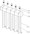
FIG. 3 is a perspective view of a rotary blade;
FIG. 4 is a schematic top view of the rotary damper;
in the figure, a water tank 1 in an experimental area, a water tank body 1.1, a camera 1.2, a water state real-time monitoring system 1.3, a first telescopic device 1.4, a blocking net 1.5, a module clamping groove 1.6, a fish driver 1.7, a PIT induction device 1.8, a rectifier grid 1.9, a filtering device 1.10, an automatic fish placing device 2, a fish storage tank 2.1, a partition plate 2.2, a lifting gate 2.3, a second telescopic device 2.4, a collecting slideway 2.5, a water storage tank 3, a water circulating device 4, a water guide pipeline 4.1, a water suction pump 4.2, a rotary gate 5, a rotary rod 5.1, a gate 5.2, a gear 5.3, a straight rack 5.4, a third telescopic device 5.5, a rotary block 5.6, a rotary shaft 5.7, a servo motor 5.8, an arc-shaped slideway 5.9, an avoiding groove 5.10, a water through hole 5.11 and a buffer groove 5.12.
Detailed Description
The invention is described in further detail below with reference to the figures and specific embodiments.
As shown in fig. 1 to 4, a full-automatic modularized fish behavior experimental device comprises an experimental area water tank 1, wherein an automatic fish placing device 2 is arranged on the front side of the experimental area water tank 1, a water storage tank 3 is arranged on the rear side of the experimental area water tank 1, a water circulating device 4 is arranged between the experimental area water tank 1 and the water storage tank 3, and a rotary gate 5 which can be switched on and off and can catch up with fish is further arranged between the outlet of the experimental area water tank 1 and the inlet of the water storage tank 3.
Preferably, the experimental area water tank 1 comprises a water tank body 1.1, a camera 1.2 is arranged above the water tank body 1.1, and a water state real-time monitoring system 1.3 is arranged in the water tank body 1.1. In the embodiment, the water tank body 1.1 can be made of transparent glass, and a plurality of light supplement lamps can be arranged at the bottom of the water tank body, so that the camera 1.2 can well shoot and record the behavior of fish in the water tank body 1.1; in addition, the water state real-time monitoring system 1.3 comprises a PH real-time monitoring device, an intelligent temperature control system, a TDS detection device and an ammonia nitrogen real-time monitoring module, and can monitor the water quality condition in real time.
More preferably, the front end of the sink body 1.1 is provided with a first telescopic device 1.4, and the first telescopic device 1.4 is connected with the top of the barrier net 1.5. The first telescopic device 1.4 in the embodiment is a pneumatic telescopic rod structure, and the barrier net 1.5 can move upwards or downwards through the extension or contraction of the first telescopic device 1.4; in addition, after the blocking net 1.5 is arranged at the front end of the water tank body 1.1, the fishes entering the water tank body 1.1 for experiment can be adapted, after the adaptation is completed, the blocking net 1.5 is moved upwards, and the fishes are placed in the middle area of the water tank body 1.1 for experiment.
More preferably, the inlet of the water tank body 1.1 is provided with a fish driving device 1.7, the outlet of the water tank body 1.1 is also provided with a PIT induction device 1.8, the PIT induction device 1.8 is connected with a controller, and the controller is connected with the control end of a driving mechanism of the rotary gate 5. In the embodiment, the PIT sensing device 1.8 adopts a sea Kangwei sight H1017C3S model, can sense the passing condition of fishes in real time, sends corresponding data to the controller when sensing that the fishes reach the outlet of the water tank body 1.1, and then the controller controls the driving mechanism of the rotary gate 5 to generate corresponding action, so that the fishes smoothly pass through the rotary gate 5; in addition, the fish driver 1.7 can adopt an underwater loudspeaker, so that the fish can swim to the outlet of the water tank body 1.1.
More preferably, the rear end of the water tank body 1.1 is provided with a module clamping groove 1.6, and the water inlet end of the water tank body 1.1 is provided with a rectifying grating 1.9 and a filtering device 1.10. The module clamping groove 1.6 in the embodiment can be used for installing other experimental devices, such as a fish luring device, a sound driving device, a bubble curtain experimental device, an optical influence experimental device and the like, so that the device can be well coupled with other experimental devices, and the functional diversity of the device is increased. The water flow entering the water tank body 1.1 can be stable and uniform through the rectifying grid 1.9, and impurities in the water can be effectively filtered through the filtering device 1.10.
Preferably, the water circulation device 4 comprises a water diversion pipeline 4.1, one end of the water diversion pipeline 4.1 is connected with a water outlet of the water storage tank 3, the other end of the water diversion pipeline 4.1 is connected with a water inlet end of the experimental area water tank 1, and a water suction pump 4.2 is further arranged on the water diversion pipeline 4.1. The water in the water storage tank 3 can be pumped back into the experimental area water tank 1 through the water suction pump 4.2, and the flow rate of the water flow in the experimental area water tank 1 can be changed by controlling the power of the water suction pump 4.2.
Preferably, automatic fish device 2 of putting includes the open storage fish case 2.1 in top, store up vertical baffle 2.2 that is equipped with the polylith parallel to each other in the fish case 2.1, store up fish case 2.1 one side and be equipped with a plurality of lift gates 2.3, lift gate 2.3 top and second telescoping device 2.4, still be equipped with between storage fish case 2.1 bottom and the 1 top in experiment area basin and receive and restraint slide 2.5. Design back baffle 2.2 like this and will store up fish case 2.1 and separate into a plurality of regions, can put into corresponding partition region respectively with many fishes like this in advance, when the experiment is done to needs, can correspond open corresponding lift gate 2.3 can, in this embodiment, second telescoping device 2.4 also is pneumatic telescopic rod structure, through the flexible process of control second telescoping device 2.4, can make lift gate 2.3 shift up or descend, receive in addition and restraint slide 2.5 and play the transition effect, make the fish slide smoothly in experimental area basin 1.
Preferably, rotatory gate 5 includes a plurality of rotary rods 5.1 of vertical setting, brake lining 5.2 is installed to rotary rod 5.1 bottom, and rotary rod 5.1 top is equipped with gear 5.3, a plurality of gears 5.3 and the meshing of spur rack 5.4, spur rack 5.4 tip is connected with third telescoping device 5.5, and every rotary rod 5.1 all wears to locate in rotatory piece 5.6 through the bearing, rotatory piece 5.6 both ends are erect in the bearing of experimental area basin 1 lateral wall through rotation axis 5.7, and wherein the rotation axis 5.7 and the servo motor 5.8 output shaft of one end, and brake lining 5.2 still is equipped with arc slide 5.9 near one side of 3 imports of catch basin. In this embodiment, the third expansion device 5.5 is an electric expansion rod or a pneumatic expansion rod, and the expansion or contraction of the third expansion device 5.5 can make the spur rack 5.4 reciprocate, so as to make the plurality of gears 5.3 rotate synchronously, and further make the rotating rod 5.1 rotate, and the rotating rod 5.1 rotates to make the brake pads 5.2 also generate corresponding actions, for example, after the rotating rod 5.1 rotates clockwise by a certain angle, the plurality of brake pads 5.2 are closed with each other, so as to make the rotary gate 5 in a closed state, and if the rotating rod 5.1 rotates counterclockwise by a certain angle, the plurality of brake pads 5.2 are separated from each other, so as to make the rotary gate 5 in an open state, similar to a "shutter" structure; in addition, when the servo motor 5.8 works, the rotating shaft 5.7 can be controlled to rotate by a certain angle, and then the rotating block 5.6 drives all the rotating rods 5.1 and the brake pads 5.2 to rotate synchronously, because the brake pads 5.2 are also provided with the arc-shaped slide ways 5.9 on one side close to the inlet of the water storage tank 3, the fish can be driven away along the arc-shaped slide ways 5.9 in the rotating process of the brake pads 5.2, the fish is not required to be manually salvaged or driven in the experimental area water tank 1, the influence on the experimental process is avoided, and the damage to the fish is also effectively reduced.
More preferably, a plurality of avoiding grooves 5.10 matched with the tops of the rotating rods 5.1 are further formed in the straight rack 5.4. Because can drive all rotary rod 5.1 and overturn together when rotatory piece 5.6 is rotatory, so the gear 5.3 at rotary rod 5.1 top also can take place to overturn, can make gear 5.3 and spur rack 5.4 separate like this, this in-process, in order not to influence the rotation process of rotary rod 5.1 and gear 5.3, offer and dodge groove 5.10 and just solved this problem well, can avoid spur rack 5.4 and pivoted rotary rod 5.1 and gear 5.3 to bump. As shown in fig. 3 and 4, after the spur rack 5.4 moves a certain distance, the avoiding groove 5.10 can be just aligned with the rotating rod 5.1 and the gear 5.3 thereof, so that there is enough space for the rotating rod 5.1 and the gear 5.3 thereof not to touch the spur rack 5.4 during the overturning process.
More preferably, a plurality of water through holes 5.11 are further formed in the brake lining 5.2, and a buffer slot 5.12 is further arranged between the arc-shaped slide way 5.9 and the water storage tank 3. The water holes 5.11 can effectively reduce the resistance of the rotation of the brake pads 5.2, so that the opening and closing of the brake pads 5.2 and the rotation process are smoother. The buffer tank 5.12 can store the fish after the experiment in a short time, and the water outlet is also provided with a screen mesh which can ensure that the water flow enters the water storage tank 3.
The working principle of the embodiment is as follows:
firstly, supplementing water into a water tank body 1.1 to ensure that a fixed amount of water is filled into both an experimental area water tank 1 and a water storage tank 3, and then starting a water suction pump 4.2, so that the water in the water storage tank 3 can be continuously pumped back into the experimental area water tank 1, the water can be reused, the flow rate of the water in the experimental area water tank 1 can be controlled according to the requirements of dynamic experiments, and if a static experiment needs to be carried out, the water suction pump 4.2 can be closed when the water needs to be kept static;
when an experiment is started, target fishes are placed into the fish storage boxes 2.1 of the automatic fish placing devices 2, when the experiment needs to be carried out, corresponding lifting gates 2.3 can be correspondingly opened, and the fishes smoothly slide into the experimental area water tanks 1 through the bundling slideways 2.5; the fish firstly enters the water tank body 1.1 for adaptation, and after adaptation is completed, the first telescopic device 1.4 is contracted to enable the blocking net 1.5 to move upwards, so that the fish is placed in the middle area of the water tank body 1.1 for an experimental process; the module clamping groove 1.6 can be used for installing other experimental devices, such as a fish luring device, a sound driving device, a bubble curtain experimental device, an optical influence experimental device and the like, so that the device can be well coupled with other experimental devices, and the functional diversity of the device is increased;
after corresponding experiments are carried out, the fish driving device 1.7 is opened, so that fishes can swim to the outlet of the water tank body 1.1, when the PIT sensing device 1.8 senses that the fishes reach the outlet of the water tank body 1.1, corresponding data are sent to the controller, and then the controller controls the driving mechanism of the rotary gate 5 to generate corresponding actions, so that the fishes smoothly pass through the rotary gate 5; the specific working principle of the rotary gate 5 is as follows:
the controller controls the third telescopic device 5.5 to extend, as shown in fig. 4, so that the spur rack 5.4 moves to the right, thereby synchronously rotating the plurality of gears 5.3, further rotating the rotating rod 5.1 counterclockwise by a certain angle, and the plurality of gate pieces 5.2 are separated from each other, thereby enabling the rotating gate 5 to be in an open state, which is similar to a "shutter" structure, in which fish can pass through gaps between the plurality of gate pieces 5.2; then, the third telescopic device 5.5 is contracted, so that the spur rack 5.4 moves towards the left side, the gears 5.3 synchronously rotate, the rotating rod 5.1 rotates clockwise for a certain angle, the brake pads 5.2 are closed, and the rotating gate 5 is in a closed state; then a servo motor 5.8 is started, a rotating shaft 5.7 rotates for a certain angle, and further a rotating block 5.6 drives all rotating rods 5.1 and brake pads 5.2 to synchronously overturn, and as the arc-shaped slide rails 5.9 are also arranged on one sides of the brake pads 5.2 close to the inlet of the water storage tank 3, fish can be driven away along the arc-shaped slide rails 5.9 in the overturning process of the brake pads 5.2, the fish can be salvaged or driven in the water tank 1 of the experimental area without manual work, so that the influence on the experimental process is avoided, and the damage to the fish is effectively reduced; the fish enters into the buffer slot 5.12 and can be stored for a short time, and its delivery port department still is equipped with the screen cloth simultaneously, can guarantee rivers through and enter into the catch basin 3 in, the experimenter can be under the circumstances of experiment completion with the fish in the buffer slot 5.12 salvage can, this process can not produce any interference to the fish action experiment.
The above-described embodiments are merely preferred embodiments of the present invention, and should not be construed as limiting the present invention, and features in the embodiments and examples in the present application may be arbitrarily combined with each other without conflict. The protection scope of the present invention is defined by the claims, and includes equivalents of technical features of the claims. I.e., equivalent alterations and modifications within the scope hereof, are also intended to be within the scope of the invention.
Claims (4)
1. The utility model provides a full-automatic modularization fish behaviouristics experimental apparatus, includes experiment area basin (1), experiment area basin (1) front side is equipped with automatic fish device (2) of putting, and experiment area basin (1) rear side is equipped with catch basin (3), its characterized in that: a water circulation device (4) is arranged between the experimental area water tank (1) and the water storage tank (3), and a rotary gate (5) which can be switched on and off and can catch fish is also arranged between the outlet of the experimental area water tank (1) and the inlet of the water storage tank (3); the rotary gate (5) comprises a plurality of vertically arranged rotary rods (5.1), a gate sheet (5.2) is installed at the bottom of each rotary rod (5.1), gears (5.3) are arranged at the tops of the rotary rods (5.1), a plurality of gears (5.3) are meshed with straight racks (5.4), the end parts of the straight racks (5.4) are connected with third telescopic devices (5.5), each rotary rod (5.1) is arranged in a rotary block (5.6) in a penetrating mode through a bearing, two ends of each rotary block (5.6) are erected in bearings on the side walls of the experimental area water tank (1) through rotary shafts (5.7), the rotary shaft (5.7) at one end is connected with an output shaft of a servo motor (5.8), and an arc-shaped slide way (5.9) is further arranged on one side, close to an inlet of the water storage tank (3), of the gate sheet (5.2);
the experimental area water tank (1) comprises a water tank body (1.1), a camera (1.2) is arranged above the water tank body (1.1), and a water state real-time monitoring system (1.3) is arranged in the water tank body (1.1);
the front end of the water tank body (1.1) is provided with a first telescopic device (1.4), and the first telescopic device (1.4) is connected with the top of the blocking net (1.5);
a fish driving device (1.7) is arranged at the inlet of the water tank body (1.1), a PIT induction device (1.8) is further arranged at the outlet of the water tank body (1.1), the PIT induction device (1.8) is connected with a controller, and the controller is connected with the control end of a driving mechanism of the rotary gate (5);
the water circulation device (4) comprises a water drainage pipeline (4.1), one end of the water drainage pipeline (4.1) is connected with a water outlet of the water storage tank (3), the other end of the water drainage pipeline (4.1) is connected with a water inlet end of the experimental area water tank (1), and a water suction pump (4.2) is further arranged on the water drainage pipeline (4.1);
automatic put fish device (2) and include open storage fish case (2.1) in top, store up vertical baffle (2.2) that are equipped with the polylith parallel to each other in fish case (2.1), store up fish case (2.1) one side and be equipped with a plurality of lift gates (2.3), lift gate (2.3) top and second telescoping device (2.4), still be equipped with between storage fish case (2.1) bottom and experimental area basin (1) top and receive and restraint slide (2.5).
2. The full-automatic modularized fish behavioral experiment device according to claim 1, characterized in that: the water tank is characterized in that a module clamping groove (1.6) is formed in the rear end of the water tank body (1.1), and a rectifying grid (1.9) and a filtering device (1.10) are arranged at the water inlet end of the water tank body (1.1).
3. The full-automatic modularized fish behavioral experiment device according to claim 1, characterized in that: and the straight rack (5.4) is also provided with a plurality of avoiding grooves (5.10) matched with the tops of the rotating rods (5.1).
4. The fully automatic modular fish behavioral experimental apparatus according to claim 1 or 3, characterized in that: still seted up a plurality of water holes (5.11) on brake lining (5.2), still be equipped with buffer slot (5.12) between arc slide (5.9) and catch basin (3).
Priority Applications (1)
| Application Number | Priority Date | Filing Date | Title |
|---|---|---|---|
| CN201911283604.0A CN110999844B (en) | 2019-12-13 | 2019-12-13 | Full-automatic modularized fish ethology experimental device |
Applications Claiming Priority (1)
| Application Number | Priority Date | Filing Date | Title |
|---|---|---|---|
| CN201911283604.0A CN110999844B (en) | 2019-12-13 | 2019-12-13 | Full-automatic modularized fish ethology experimental device |
Publications (2)
| Publication Number | Publication Date |
|---|---|
| CN110999844A CN110999844A (en) | 2020-04-14 |
| CN110999844B true CN110999844B (en) | 2022-02-01 |
Family
ID=70114736
Family Applications (1)
| Application Number | Title | Priority Date | Filing Date |
|---|---|---|---|
| CN201911283604.0A Active CN110999844B (en) | 2019-12-13 | 2019-12-13 | Full-automatic modularized fish ethology experimental device |
Country Status (1)
| Country | Link |
|---|---|
| CN (1) | CN110999844B (en) |
Families Citing this family (3)
| Publication number | Priority date | Publication date | Assignee | Title |
|---|---|---|---|---|
| CN112502089A (en) * | 2020-12-08 | 2021-03-16 | 中国电建集团昆明勘测设计研究院有限公司 | Fish lifting machine system and method suitable for mountainous regions and river valleys |
| CN112400819B (en) * | 2020-12-08 | 2024-01-26 | 中国电建集团昆明勘测设计研究院有限公司 | Fish trapping system and method applicable to mountain river in fish lift engineering |
| CN115500309B (en) * | 2022-10-28 | 2023-07-11 | 中国水产科学研究院淡水渔业研究中心 | Device and method for measuring fish behaviors |
Citations (9)
| Publication number | Priority date | Publication date | Assignee | Title |
|---|---|---|---|---|
| JP2003245047A (en) * | 2002-02-22 | 2003-09-02 | Tetsuhiro Kawakami | Method for producing tempura and deep-fried food |
| CN2875056Y (en) * | 2006-01-27 | 2007-03-07 | 上海市长江口中华鲟自然保护区管理处 | Means for liberating fishes into natural water |
| CN101084347A (en) * | 2004-12-27 | 2007-12-05 | 姜湳 | Fishway block |
| CN203684183U (en) * | 2014-01-26 | 2014-07-02 | 三峡大学 | Fish inducing grid capable of being assembled |
| CN204825811U (en) * | 2015-07-27 | 2015-12-02 | 徐州市铜山区水利机械化施工处 | Pump station arc trash rack bars piece that blocks water |
| CN205314069U (en) * | 2016-01-08 | 2016-06-15 | 山东交通学院 | Trash device that can overturn |
| CN207612936U (en) * | 2017-12-18 | 2018-07-17 | 三峡大学 | A kind of biology phototaxis experimental provision |
| CN208039148U (en) * | 2018-04-03 | 2018-11-02 | 三峡大学 | Fish pass import moisturizing attracting experimental trough |
| CN110050730A (en) * | 2019-05-23 | 2019-07-26 | 中国长江三峡集团有限公司 | It is a kind of to test fish to the experimental provision and method of air curtain and light approach behavior |
Family Cites Families (10)
| Publication number | Priority date | Publication date | Assignee | Title |
|---|---|---|---|---|
| SU1740539A1 (en) * | 1990-10-19 | 1992-06-15 | Новочеркасский инженерно-мелиоративный институт им.А.К.Кортунова | Fish hoist |
| JP4412584B2 (en) * | 2003-09-01 | 2010-02-10 | 株式会社三矢 | Crushing fluid dryer |
| CN101317553B (en) * | 2007-11-27 | 2011-08-17 | 浙江海洋学院 | Tester for acousto-optic-electric action of fishes |
| CN100552146C (en) * | 2008-02-13 | 2009-10-21 | 黎宗圣 | Waterpower self-control type gate |
| CN104430083A (en) * | 2014-11-21 | 2015-03-25 | 广东省渔业种质保护中心 | Water cycle aquatic breeding system and aquatic breeding method |
| CN106049377B (en) * | 2016-06-06 | 2017-12-29 | 中国水利水电科学研究院 | Induce the fish pass inlet system and design method and attracting flow velocity calibration device of grass carp |
| CN206629791U (en) * | 2017-04-17 | 2017-11-14 | 三峡大学 | A kind of novel fish luminous environment preference choice experiment device |
| CN207828929U (en) * | 2017-12-12 | 2018-09-07 | 绵竹鑫优创机械制造有限公司 | A kind of fish device excessively of water conservancy and hydropower dam |
| CN108560478B (en) * | 2018-02-13 | 2023-05-02 | 贵州省水利水电勘测设计研究院 | Movable chargeable fish-catching grid device |
| CN108157261B (en) * | 2018-03-15 | 2023-06-27 | 贵州省水利水电勘测设计研究院 | Fish sorting device for fish lifting machine |
-
2019
- 2019-12-13 CN CN201911283604.0A patent/CN110999844B/en active Active
Patent Citations (9)
| Publication number | Priority date | Publication date | Assignee | Title |
|---|---|---|---|---|
| JP2003245047A (en) * | 2002-02-22 | 2003-09-02 | Tetsuhiro Kawakami | Method for producing tempura and deep-fried food |
| CN101084347A (en) * | 2004-12-27 | 2007-12-05 | 姜湳 | Fishway block |
| CN2875056Y (en) * | 2006-01-27 | 2007-03-07 | 上海市长江口中华鲟自然保护区管理处 | Means for liberating fishes into natural water |
| CN203684183U (en) * | 2014-01-26 | 2014-07-02 | 三峡大学 | Fish inducing grid capable of being assembled |
| CN204825811U (en) * | 2015-07-27 | 2015-12-02 | 徐州市铜山区水利机械化施工处 | Pump station arc trash rack bars piece that blocks water |
| CN205314069U (en) * | 2016-01-08 | 2016-06-15 | 山东交通学院 | Trash device that can overturn |
| CN207612936U (en) * | 2017-12-18 | 2018-07-17 | 三峡大学 | A kind of biology phototaxis experimental provision |
| CN208039148U (en) * | 2018-04-03 | 2018-11-02 | 三峡大学 | Fish pass import moisturizing attracting experimental trough |
| CN110050730A (en) * | 2019-05-23 | 2019-07-26 | 中国长江三峡集团有限公司 | It is a kind of to test fish to the experimental provision and method of air curtain and light approach behavior |
Non-Patent Citations (1)
| Title |
|---|
| 水流对草鱼幼鱼趋光行为的影响;张宁等;《水生生物学报》;20191130;第43卷(第6期);第1254-1261页 * |
Also Published As
| Publication number | Publication date |
|---|---|
| CN110999844A (en) | 2020-04-14 |
Similar Documents
| Publication | Publication Date | Title |
|---|---|---|
| CN110999844B (en) | Full-automatic modularized fish ethology experimental device | |
| CN206800347U (en) | The transporting something containerized fish platform on dam is crossed for fish | |
| CN206052633U (en) | Automatic phosgene attracting system based on collection fishing boat | |
| CN111789070A (en) | Energy-saving automatic edible fish feeding aquaculture pond | |
| CN109197731A (en) | A kind of holothruian cultures and automatic fishing gear | |
| CN207784011U (en) | Facilitate the freshwater fish culturing pond of fishing | |
| CN206728926U (en) | A kind of lobster cultivation equipment | |
| CN113728986A (en) | Layered fishing device for giant deepwater net cage and use method thereof | |
| CN108124809A (en) | Compound freshwater fish culturing pond | |
| CN107094681A (en) | A kind of current -resistance submerged cage | |
| CN207870098U (en) | Novel partition type freshwater fish culturing pond | |
| CN101402472A (en) | Aquatic ecology renovation machine | |
| CN206150096U (en) | Cascade is used in chicken coop cooling | |
| CN207836519U (en) | Facilitate the fish pond of fishing | |
| CN110876354A (en) | Circulating water culture system with position-controllable water outlet layer | |
| CN203155345U (en) | Medium mixing and adding apparatus | |
| CN211932068U (en) | Lobster is bred with putting seedling device | |
| CN212116707U (en) | Circulating water culture system with position-controllable water outlet layer | |
| CN207836520U (en) | Growth fishing cellular-type fish pond | |
| CN209089731U (en) | Aphid parasite, wasp fly hollow drum drainage device | |
| CN211198760U (en) | Water environment ecological restoration device | |
| CN211621478U (en) | Dam water inlet refuse treatment device | |
| CN112189614A (en) | Novel pond land-based experiment enclosure integrated system | |
| CN201617093U (en) | Offshore abalone hanging culture device | |
| CN112219766B (en) | Artificial automatic marine ranch |
Legal Events
| Date | Code | Title | Description |
|---|---|---|---|
| PB01 | Publication | ||
| PB01 | Publication | ||
| SE01 | Entry into force of request for substantive examination | ||
| SE01 | Entry into force of request for substantive examination | ||
| GR01 | Patent grant | ||
| GR01 | Patent grant |